Instrument approaches have requirements to fly and land
These approach and landing requirements are established in Federal Aviation Regulation (FAR) 91.175
Approach and Landing Minimums:
If an aircraft which has been cleared to a holding fix and subsequently "cleared...approach" has not received new routing, and even though clearance for the approach may have been issued prior to the aircraft reaching the holding fix, then ATC would expect the pilot to proceed via the holding fix and the feeder route associated with that fix
When cleared for the approach, the published off airway (feeder) routes that lead from the en-route structure to the IAF are part of the approach clearance
If a feeder route to an Instrument Approach Fix (IAF) begins at a fix, located along the route of flight prior to reaching the holding fix, and clearance for an approach is issued, a pilot should commence the approach via the published feeder route; i.e., the aircraft would not be expected to overfly the feeder route and return to it
If a route of flight directly to the IAF is desired, it should be stated by the controller with phraseology to include the words "direct...," "proceed direct..." or a similar phrase
The name of the approach is used to identify the approach, even though a component such as the glide slope on an ILS is inoperative
The controller will use the name as published but must advise the aircraft at the time of inoperative equipment
The pilot, not the controller, is responsible for determining your unique requirements/minimums
Note that in the absence of a local altimeter setting/ATIS, approach minimums may increase as per the chart or ATC restriction
Pilot Briefing and Procedures Notes:
Pilot briefing and procedures notes provide additional information that may need to be applied to an approach
Examples:
When a local altimeter has not been received, DA or MDA may need to be added to the published DA or MDA
Definitions:
Holding Fix: a location which is identifiable to a pilot to be used as reference point in establishing and maintaining the position of an aircraft
Feeder Routes: routes that direct pilots toward a location, such as a holding fix for an instrument approach
Approach Clearance:
An aircraft which has been cleared to a holding fix and subsequently "cleared . . . approach" has not received new routing. Even though clearance for the approach may have been issued prior to the aircraft reaching the holding fix, ATC would expect the pilot to proceed via the holding fix (his/her last assigned route), and the feeder route associated with that fix (if a feeder route is published on the approach chart) to the initial approach fix (IAF) to commence the approach. WHEN CLEARED FOR THE APPROACH, THE PUBLISHED OFF AIRWAY (FEEDER) ROUTES THAT LEAD FROM THE EN ROUTE STRUCTURE TO THE IAF ARE PART OF THE APPROACH CLEARANCE
If a feeder route to an IAF begins at a fix located along the route of flight prior to reaching the holding fix, and clearance for an approach is issued, a pilot should commence the approach via the published feeder route; i.e., the aircraft would not be expected to overfly the feeder route and return to it. The pilot is expected to commence the approach in a similar manner at the IAF, if the IAF for the procedure is located along the route of flight to the holding fix
If a route of flight directly to the initial approach fix is desired, it should be so stated by the controller with phraseology to include the words "direct . . . ," "proceed direct" or a similar phrase which the pilot can interpret without question. When uncertain of the clearance, immediately query ATC as to what route off light is desired
The name of an instrument approach, as published, is used to identify the approach, even though a component of the approach aid, such as the glideslope on an Instrument Landing System, is inoperative or unreliable. The controller will use the name of the approach as published, but must advise the aircraft at the time an approach clearance is issued that the inoperative or unreliable approach aid component is unusable, except when the title of the published approach procedures otherwise allows; for example, ILS Rwy 05 or LOC Rwy 05
The following applies to aircraft on radar vectors and/or cleared "direct to" in conjunction with an approach clearance:
Maintain the last altitude assigned by ATC until the aircraft is established on a published segment of a transition route, or approach procedure segment, or other published route, for which a lower altitude is published on the chart. If already on an established route, or approach or arrival segment, you may descend to whatever minimum altitude is listed for that route or segment
Continue on the vector heading until intercepting the next published ground track applicable to the approach clearance
Once reaching the final approach fix via the published segments, the pilot may continue on approach to a landing
If proceeding to an IAF with a published course reversal (procedure turn or hold-in-lieu of PT pattern), except when cleared for a straight in approach by ATC, the pilot must execute the procedure turn/hold-in-lieu of PT, and complete the approach
If cleared to an IAF/IF via a NoPT route, or no procedure turn/hold-in-lieu of PT is published, continue with the published approach
In addition to the above, RNAV aircraft may be issued a clearance direct to the IAF/IF at intercept angles not greater than 90 degrees for both conventional and RNAV instrument approaches. Controllers may issue a heading or a course direct to a fix between the IF and FAF at intercept angles not greater than 30 degrees for both conventional and RNAV instrument approaches. In all cases, controllers will assign altitudes that ensure obstacle clearance and will permit a normal descent to the FAF. When clearing aircraft direct to the IF, ATC will radar monitor the aircraft until the IF and will advise the pilot to expect clearance direct to the IF at least 5 miles from the fix. ATC must issue a straight-in approach clearance when clearing an aircraft direct to an IAF/IF with a procedure turn or hold-in-lieu of a procedure turn, and ATC does not want the aircraft to execute the course reversal
Refer to 14 CFR 91.175 (i)
RNAV aircraft may be issued a clearance direct to the FAF that is also charted as an IAF, in which case the pilot is expected to execute the depicted procedure turn or hold-in-lieu of procedure turn. ATC will not issue a straight-in approach clearance. If the pilot desires a straight-in approach, they must request vectors to the final approach course outside of the FAF or fly a published "NoPT" route. When visual approaches are in use, ATC may clear an aircraft direct to the FAF
In anticipation of a clearance by ATC to any fix published on an instrument approach procedure, pilots of RNAV aircraft are advised to select an appropriate IAF or feeder fix when loading an instrument approach procedure into the RNAV system
Selection of "Vectors-to-Final" or "Vectors" option for an instrument approach may prevent approach fixes located outside of the FAF from being loaded into an RNAV system. Therefore, the selection of these options is discouraged due to increased workload for pilots to reprogram the navigation system
Arrival Holding
Some approach charts have an arrival holding pattern depicted at an IAF or at a feeder fix located along an airway. The arrival hold is depicted using a "thin line" since it is not always a mandatory part of the instrument procedure
Arrival holding is charted where holding is frequently required prior to starting the approach procedure so that detailed holding instructions are not required. The arrival holding pattern is not authorized unless assigned by ATC. Holding at the same fix may also be depicted on the en route chart
Arrival holding is also charted where it is necessary to use a holding pattern to align the aircraft for procedure entry from an airway due to turn angle limitations imposed by procedure design standards. When the turn angle from an airway into the approach procedure exceeds the permissible limits, an arrival holding pattern may be published along with a note on the procedure specifying the fix, the airway, and arrival direction where use of the arrival hold is required for procedure entry. Unlike a hold-in-lieu of procedure turn, use of the arrival holding pattern is not authorized until assigned by ATC. If ATC does not assign the arrival hold before reaching the holding fix, the pilot should request the hold for procedure entry. Once established on the inbound holding course and an approach clearance has been received, the published procedure can commence. Alternatively, if using the holding pattern for procedure entry is not desired, the pilot may ask ATC for maneuvering airspace to align the aircraft with the feeder course
Example: Planview Chart Note: "Proc NA via V343 northeast bound without holding at JOXIT. ATC CLNC REQD"
An RF leg is defined as a constant radius circular path around a defined turn center that starts and terminates at a fix. An RF leg may be published as part of a procedure. Since not all aircraft have the capability to fly these leg types, pilots are responsible for knowing if they can conduct an RNAV approach with an RF leg. Requirements for RF legs will be indicated on the approach chart in the notes section or at the applicable initial approach fix. Controllers will clear RNAV-equipped aircraft for instrument approach procedures containing RF legs:
Via published transitions, or
In accordance with RNAV procedures above
ATC will not clear aircraft direct to any waypoint beginning or within an RF leg, and will not assign fix/waypoint crossing speeds in excess of charted speed restrictions
EXAMPLE:
Controllers will not clear aircraft direct to THIRD because that waypoint begins the RF leg, and aircraft cannot be vectored or cleared to TURNN or vectored to intercept the approach segment at any point between THIRD and FORTH because this is the RF leg
When necessary to cancel a previously issued approach clearance, the controller will advise the pilot "Cancel Approach Clearance" followed by any additional instructions when applicable
Approach Clearances:
You are not cleared to land until tower issues the clearance
If cleared for the approach by approach control you must wait for tower or query tower to give you a landing clearance
Where two or more IAPs are published, pilots will be provided in advance of their arrival with the type of approach to expect or that they may be vectored for a visual approach
Broadcast by the controller or ATIS will not be furnished when the visibility is 3 miles or better and the ceiling is at or above the highest initial approach altitude for any low approach established
Once cleared for an approach you must report "commencing" or "leaving [Altitude]" as per mandatory calls
This is made at the IAF even if you're not changing altitudes so commencing is a better phrase
"Cleared for the approach"
Execute any published approach procedure to the airfield but state your intentions
"Cleared for TACAN approach"
Execute any published TACAN approach procedure to the airfield but state your intention
"Cleared for straight-in TACAN approach"
Execute any published TACAN approach procedure to the active runway which has straight-in minimums authorized, but state your intentions
"Cleared for Hi-TACAN runway 24"
Execute the published TACAN approach procedure for Runway 24 and land straight-in on Runway 24
"Cleared for Hi-TACAN runway 24 approach, circle to land runway 6"
Execute the published TACAN approach procedure for runway 24. Obtain the runway environment and visually circle and land on runway 6 (landing minimums to the adjacent runway will be higher than to the primary runway)
"Cleared for ILS runway 7 left approach, side-step to runway 7 right"
Execute the side-step maneuver as soon as possible after the runway or runway environment is in sight (landing minimums to the adjacent runway will be higher than the minimum to the primary runway, but will normally be lower than the published circling minimums)
When making an IFR approach to an airport not served by a tower or FSS, and after ATC advises "change to advisory frequency approved" you should broadcast your intentions including the type of approach being executed, your position, and when over the final approach fix inbound
Pilot Discretion Means:
Leave when you want
Stop if you want
Do it at the rate you want
Visual Descent Point (VDP):
VDP Depiction
The VDP is a point on the final approach course for a non-precision straight-in approach procedure from which a normal descent from the MDA to the runway touchdown may be commenced, provided reference to the runway has been obtained
The VDP will normally be identified by DME
Charted with a V symbol [Figure 1]
Advisory in nature but provide additional guidance where implemented
No special technique is required to use
The pilot should not descend below MDA prior to reaching the VDP, regardless
Pilots not equipped to receive the VDP should fly the procedure as if no VDP had been provided
VDP Depiction
Runway Environment:
Criteria for the civil pilot continuing an approach is stated in FAR 91.175 as:
Where a Decision Height (DH)/Decision Altitude (DA) or Minimum Descent Altitude (MDA) is applicable, no pilot may operate an aircraft, except a military of the United States, at any airport below the authorized MDA or continue an approach below the authorized DH unless:
The aircraft is continuously in a position from which a descent to a landing on the intended runway can be made at a normal rate of descent using normal maneuvers, and for operations conducted under part 121 or part 135 unless that descent rate will allow touchdown to occur within the touchdown zone of the runway of indented landing;
The flight visibility is not less than the visibility prescribed in the standard instrument approach being used;
Except for Category II or Category III approach where any necessary visual reference requirements are specified by the Administrator, at least one of the following visual reference for the intended runway is distinctly visible and identifiable to the pilot
The approach light system, except that the pilot may not descend below 100' above the touchdown zone elevation using the approach lights as a reference unless the red side row bars are also distinctly visible and identifiable
No pilot operating an aircraft, except a military aircraft of the United States, may land that aircraft when the flight visibility is less than the visibility prescribed in the standard instrument approach procedure being used
Obstacle Clearance:
Final Approach Obstacle Clearance
Standard and Expanded Circling Approach Radii in the U.S. TPP
Final approach obstacle clearance is provided from the start of the final segment to the runway or Missed Approach Point (MAP) whichever occurs last
If a Sidestep option is incorporated into the approach then obstacle protection is provided by increasing the width of the final approach obstacle clearance area
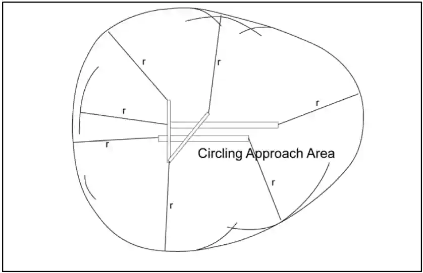
Circling approach: tangential connection of arcs drawn from each runway end, obstacles unable to be cleared will be given rules
Example: circling NA E of RWY 17-35, meaning circling not authorized east of runway 17-35
Circling approach protected areas are defined by the tangential connection of arcs drawn from each runway end [Figure 2]
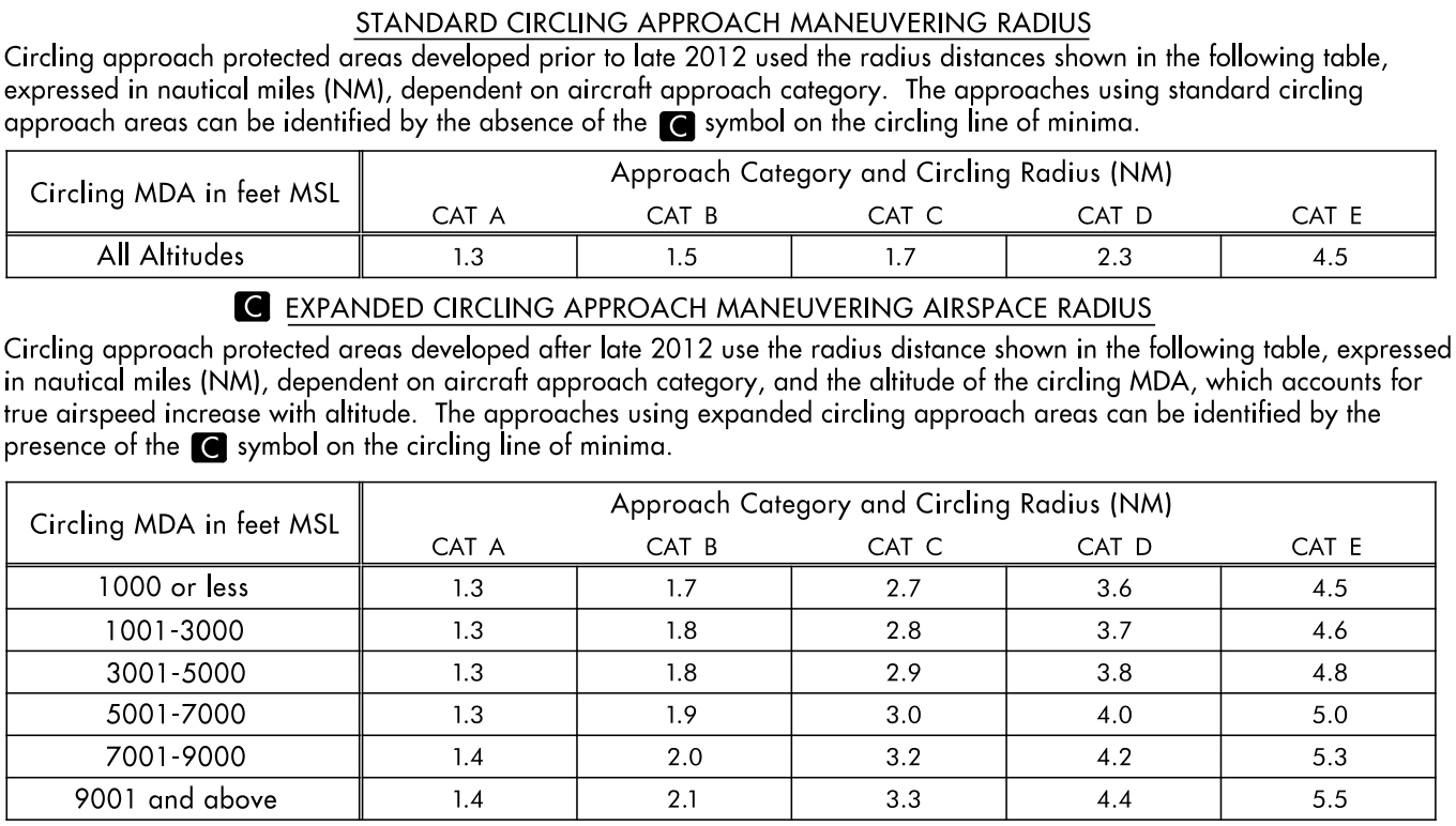
Circling approach protected areas developed prior to late 2012 used fixed radius distances, dependent on aircraft approach category, as shown in the table on page B2 of the U.S. TPP
The approaches using standard circling approach areas can be identified by the absence of the "negative C" symbol on the circling line of minima
Circling approach protected areas developed after late 2012 use the radius distance shown in the table on page B2 of the U.S. TPP, dependent on aircraft approach category, and the altitude of the circling MDA, which accounts for true airspeed increase with altitude
The approaches using expanded circling approach areas can be identified by the presence of the "negative C" symbol on the circling line of minima [Figure 3]
Because of obstacles near the airport, a portion of the circling area may be restricted by a procedural note; for example, "Circling NA E of RWY 17-35." Obstacle clearance is provided at the published minimums (MDA) for the pilot who makes a straight-in approach, side-steps, or circles. Once below the MDA the pilot must see and avoid obstacles. Executing the missed approach after starting to maneuver usually places the aircraft beyond the MAP. The aircraft is clear of obstacles when at or above the MDA while inside the circling area, but simply joining the missed approach ground track from the circling maneuver may not provide vertical obstacle clearance once the aircraft exits the circling area. Additional climb inside the circling area may be required before joining the missed approach track. See Paragraph 5-4-21, Missed Approach, for additional considerations when starting a missed approach at other than the MAP
Final Approach Obstacle Clearance
Standard and Expanded Circling Approach Radii in the U.S. TPP
Circling Instructions Example
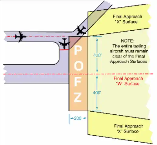
Precision Obstacle Free Zone (POFZ):
A volume of airspace above an area beginning at the runway threshold, at threshold elevation, and centered on the extended runway centerline
POFZ is 200' (60m) long and 800' (240m) wide
The POFZ must be clear when an aircraft on a vertically guided final approach is within 2 Nautical Mile (NM) of the runway threshold and the ceiling is below 250' or visibility is less than 3/4 Statue Miles (SM)(or runway visual range below 4,000 feet)
If the POFZ is not clear, the MINIMUM authorized height above touchdown (HAT) and visibility is 250' and 3/4 SM
The POFZ is considered clear even if the wing of the aircraft holding on a taxiway waiting for runway clearance penetrates the POFZ; however, neither the fuselage nor the tail may infringe on the POFZ
The POFZ is applicable at all runway ends including displaced thresholds
Published Approach Minimums:
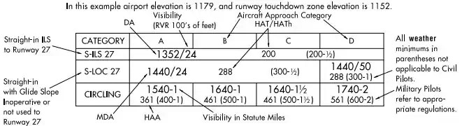
Approach minimums are published for different aircraft categories and consist of a minimum altitude (DA, DH, MDA) and required visibility
These minimums are determined by applying the appropriate TERPS criteria
When a fix is incorporated in a nonprecision final segment, two sets of minimums may be published: one for the pilot that is able to identify the fix, and a second for the pilot that cannot
Two sets of minimums may also be published when a second altimeter source is used in the procedure
When a nonprecision procedure incorporates both a stepdown fix in the final segment and a second altimeter source, two sets of minimums are published to account for the stepdown fix and a note addresses minimums for the second altimeter source
Straight-in Minimums:
Obstacle clearance is provided within 30° of the runway alignment and a normal descent can be made from the IFR altitude shown on the IAP to the runway surface
When either the normal rate of descent or the runway alignment factor of 30 degrees is exceeded, a straight-in minimum is not published and a circling minimum applies
The fact that a straight-in minimum is not published does not preclude pilots from landing straight-in if they have the active runway in sight and sufficient time to make a normal approach for landing
Under such conditions and when ATC has cleared them for landing on that runway, pilots are not expected to circle even though only circling minimums are published
If they desire to circle, they should advise ATC
Side-Step Maneuver Minimums:
Landing minimums for a side-step maneuver to the adjacent runway will normally be higher than the minimums to the primary runway
Circling Minimums:
In some busy terminal areas, ATC may not allow circling and circling minimums will not be published. Published circling minimums provide obstacle clearance when pilots remain within the appropriate area of protection. Pilots should remain at or above the circling altitude until the aircraft is continuously in a position from which a descent to a landing on the intended runway can be made at a normal rate of descent using normal maneuvers. Circling may require maneuvers at low altitude, at low airspeed, and in marginal weather conditions. Pilots must use sound judgment, have an in-depth knowledge of their capabilities, and fully understand the aircraft performance to determine the exact circling maneuver since weather, unique airport design, and the aircraft position, altitude, and airspeed must all be considered. The following basic rules apply:
Maneuver the shortest path to the base or downwind leg, as appropriate, considering existing weather conditions. There is no restriction from passing over the airport or other runways
It should be recognized that circling maneuvers may be made while VFR or other flying is in progress at the airport. Standard left turns or specific instruction from the controller for maneuvering must be considered when circling to land
At airports without a control tower, it may be desirable to fly over the airport to observe wind and turn indicators and other traffic which may be on the runway or flying in the vicinity of the airport
REFERENCE-AC 90-66A, Recommended Standards Traffic patterns for Aeronautical Operations at Airports without Operating Control Towers
The missed approach point (MAP) varies depending upon the approach flown. For vertically guided approaches, the MAP is at the decision altitude/decision height. Non-vertically guided and circling procedures share the same MAP and the pilot determines this MAP by timing from the final approach fix, by a fix, a NAVAID, or a waypoint. Circling from a GLS, an ILS without a localizer line of minima or an RNAV (GPS) approach without an LNAV line of minima is prohibited
Instrument Approach at a Military Field:
When instrument approaches are conducted by civil aircraft at military airports, they must be conducted in accordance with the procedures and minimums approved by the military agency having jurisdiction over the airport
There really is no difference between a military approach plate and a civilian approach plate other than who originated the procedure
The approach and landing minimums (as well as the rest of the plate) will read the same
DOD procedures are defined using the abbreviation of the applicable military service in parenthesis; e.g., (USAF), (USN), (USA) while Civil procedures are defined with "FAA" in parenthesis; e.g., (FAA)
Unless an emergency exists, civil aircraft operating at military airports normally require advance authorization, commonly referred to as "Prior Permission Required" or "PPR"
Information on obtaining a PPR for a particular military airport can be found in the Chart Supplement U.S.
Straight-in Approach Minimum Explanation
Landing Criteria:
Criteria for operating below the DH/DA or MDA for civilian pilots is clearly stated in FAR 91.175(c)(3)
These requirements call for three criteria:
In a position to make a safe landing
The runway environment is in sight
Visibility requirements are met (note no ceiling requirements)
Remember:
A clearance for a specific type of approach to an aircraft operating on an IFR flight plan does not mean that landing priority will be given over other traffic
Towers handle all aircraft regardless of flight plan on a "first-come, first-serve" basis
It may be necessary for the controller to provide a different landing sequence
In any case, a landing sequence will be issued to each aircraft as soon as possible
When reaching the Final Approach Fix (FAF) you must report it
When breaking out, if you have a Heads-Up-Display (HUD) with a "ghost vector," check its location before you make a play for the runway as a crosswind correction put in may already have you set up perfectly for the runway
When approach terminates IFR on a visual approach, contact tower, if not told so
If you may not break out, tell approach control and put your draft on request as an advisory to ATC
Note where you break out, should you have to go back into the weather
Runway Visual Range:
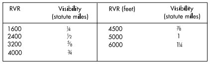
Runway Visual Range (RVR) is a tool used to determine ground or flight visibility in deciding whether or not to shoot an approach
For converting RVR values that fall between listed values, use the next higher RVR value; do not interpolate
Example: when converting 1800 RVR, use 2400 RVR with the resultant visibility of 1/2 mile
There are currently two configurations of RVR in the NAS commonly identified as Taskers and New Generation RVR
The Taskers are the existing configuration which uses transmissometer technology
The New Generation RVRs were deployed in November 1994 and use forward scatter technology
The New Generation RVRs are currently being deployed in the NAS to replace the existing Taskers
RVR values are measured by transmissometers mounted on 14-foot towers along the runway which consists of:
Transmissometer projector and related items
Transmissometer receiver (detector) and related items
Analog recorder
Signal data converter and related items
Remote digital or remote display programmer
The transmissometer projector and receiver are mounted on towers 250 feet apart. A known intensity of light is emitted from the projector and is measured by the receiver. Any obscuring matter such as rain, snow, dust, fog, haze or smoke reduces the light intensity arriving at the receiver. The resultant intensity measurement is then converted to an RVR value by the signal data converter. These values are displayed by readout equipment in the associated air traffic facility and updated approximately once every minute for controller issuance to pilots
The signal data converter receives information on the high intensity runway edge light setting in use (step 3, 4, or 5); transmission values from the transmissometer and the sensing of day or night conditions. From the three data sources, the system will compute appropriate RVR values
An RVR transmissometer established on a 250 foot baseline provides digital readouts to a minimum of 600 feet, which are displayed in 200 foot increments to 3,000 feet and in 500 foot increments from 3,000 feet to a maximum value of 6,000 feet
RVR values for Category IIIa operations extend down to 700 feet RVR; however, only 600 and 800 feet are reportable RVR increments. The 800 RVR reportable value covers a range of 701 feet to 900 feet and is therefore a valid minimum indication of Category IIIa operations
Note that while several approaches will include both RVR and Flight Visibility numbers but that is not always the case - such as on Non-Precision approaches
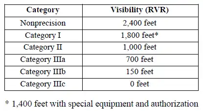
Approach categories with the corresponding minimum RVR values [Figure 5]
Approach Category/Minimum RVR Table
Ten minute maximum and minimum RVR values for the designated RVR runway are reported in the body of the aviation weather report when the prevailing visibility is less than one mile and/or the RVR is 6,000 feet or less. ATCTs report RVR when the prevailing visibility is 1 mile or less and/or the RVR is 6,000 feet or less
Details on the requirements for the operational use of RVR are contained in FAA AC 97-1, "Runway Visual Range (RVR)." Pilots are responsible for compliance with minimums prescribed for their class of operations in the appropriate CFRs and/or operations specifications
RVR values are also measured by forward scatter meters mounted on 14-foot frangible fiberglass poles. A full RVR system consists of:
Forward scatter meter with a transmitter, receiver and associated items
A runway light intensity monitor (RLIM)
An ambient light sensor (ALS)
A data processor unit (DPU)
Controller display (CD)
The forward scatter meter is mounted on a 14-foot frangible pole. Infrared light is emitted from the transmitter and received by the receiver. Any obscuring matter such as rain, snow, dust, fog, haze or smoke increases the amount of scattered light reaching the receiver. The resulting measurement along with inputs from the runway light intensity monitor and the ambient light sensor are forwarded to the DPU which calculates the proper RVR value. The RVR values are displayed locally and remotely on controller displays
The runway light intensity monitors both the runway edge and centerline light step settings (steps 1 through 5). Centerline light step settings are used for CAT IIIb operations. Edge Light step settings are used for CAT I, II, and IIIa operations
New Generation RVRs can measure and display RVR values down to the lowest limits of Category IIIb operations (150 feet RVR). RVR values are displayed in 100 feet increments and are reported as follows:
100-feet increments for products below 800'
200-feet increments for products between 800 feet and 3,000'
500-feet increments for products between 3,000 feet and 6,500'
25-meter increments for products below 150 meters
50-meter increments for products between 150 meters and 800 meters
100-meter increments for products between 800 meters and 1,200 meters
200-meter increments for products between 1,200 meters and 2,000 meters
Runway Visual Range (RVR)
Criteria for Continuing Instrument Approaches to a Landing:
Pilots shall not descend below the prescribed MDA or continue an approach below the decision height (DH) unless they have the runway environment in sight and in their judgment a safe landing can be executed, either straight-in or from a circling approach, whichever is specified in their clearance
Precision Approaches: A missed approach shall be executed immediately upon reaching the DH unless the runway environment is in sight and a safe landing can be made. On precision radar approaches, the pilot may expect control instructions until over landing threshold; course and glide path information given after DH shall be considered advisory in nature
Non-Precision Approaches: A missed approach shall be executed immediately upon reaching the MAP if visual reference is not established and/or a landing cannot be accomplished. If visual reference is lost while circling to land from a published instrument approach, the missed approach specified for that particular procedure must be followed. To become established on the prescribed missed approach course, the pilot should make an initial climbing turn toward the landing runway then maneuver in the shortest direction to become established on the missed approach course
Landing Priority:
A clearance for a specific type of approach (ILS, RNAV, GLS, ADF, VOR or Visual Approach) to an aircraft operating on an IFR flight plan does not mean that landing priority will be given over other traffic
ATCTs handle all aircraft, regardless of the type of flight plan, on a "first-come, first-served" basis
Therefore, because of local traffic or runway in use, it may be necessary for the controller in the interest of safety, to provide a different landing sequence
In any case, a landing sequence will be issued to each aircraft as soon as possible to enable the pilot to properly adjust the aircraft's flight path
Conclusion:
Occasionally, multiple approaches of the same type may be published to the same runway
In these instances, lower minimums may be the reason, but non-standard performance may be required for the lower approach, necessitating standard approach parameters with higher minimums
Be sure not to transition from instrument to visual when the runway environment comes into sight, only to lose it again in the weather
Breaking out of the weather, especially at night, may be gradual and not support an immediate transition to visual flying