Airport lighting systems provide a standardized layout of positional lights and colors for pilots to reference both in the air and on ground
Airport lighting helps the pilot locate and define the runway and airport environment
Airport lighting is not continuous at airports with minimal traffic to save money when not in use
Runway edge lights, in-pavement lights, and sequence flashing lights may also have intensity controls which may be varied to meet the pilot's request
Airport lighting may be either continuous or variable, depending on traffic/use
In addition to surface airport lighting, lighting systems for the purpose of obstacle identification and avoidance are provided where necessary
Busier airports may have more advanced systems, such as the runway status light system, whereby lighting colors and behavior are responsive to real-time traffic activity
Airport Lighting Requirements:
The Office of Airport Safety and Standards Airport Engineering Division (AAS-100) is responsible for developing engineering, design, and construction standards for civil airports, heliports, and seaplane bases
Operation of approach and runway lighting may be adjusted at the pilot's discretion and is generally controlled by the Air Traffic Control Tower (ATCT)
At some locations where there is no control tower in operation, the local Flight Service Station (FSS) may control the lights
Pilots may request, and in some cases, control lighting themselves
Runway edge lights, in-pavement lights, and approach lights also have intensity controls which may be varied to meet the pilot's request
Sequenced flashing lights (SFL) may be turned on and off, but only some sequenced flashing light systems also have intensity control
Pilot Controlled Lighting:
Radio control of lighting is available at selected airports to provide airborne control of lights by keying the aircraft's microphone
Control of lighting systems is often available at locations without specified hours for lighting and where there is no control tower or FSS or when the tower or FSS is closed (locations with a part-time tower or FSS) or specified hours
All lighting systems that are radio-controlled at an airport, whether on a single runway or multiple runways, operate on the same radio frequency [Figure 1/2]
Controlled on one frequency, usually CTAF, but not always
Chart Supplement U.S. or DoD En-route supplement will list information on type, runway, and frequency used
With FAA-approved systems, various combinations of medium-intensity approach lights, runway lights, taxiway lights, VASI, and/or REIL may be activated by radio control
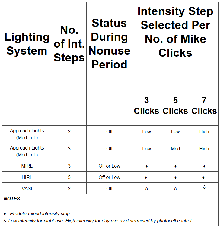
On runways with both approach lighting and runway lighting (runway edge lights, taxiway lights, etc.) systems, the approach lighting system takes precedence for air-to-ground radio control over the runway lighting system, which is set at a predetermined intensity step, based on expected visibility conditions
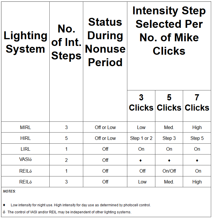
Runways without approach lighting may provide radio-controlled intensity adjustments of runway edge lights. Other lighting systems, including VASI, REIL, and taxiway lights, may be either controlled with the runway edge lights or controlled independently of the runway edge lights
The control system consists of a 3-step control responsive to 7, 5, and/or 3 microphone clicks
This 3-step control will turn on lighting facilities capable of either 3-step, 2-step, or 1-step operation
The 3-step and 2-step lighting facilities can be altered in intensity, while the 1-step cannot
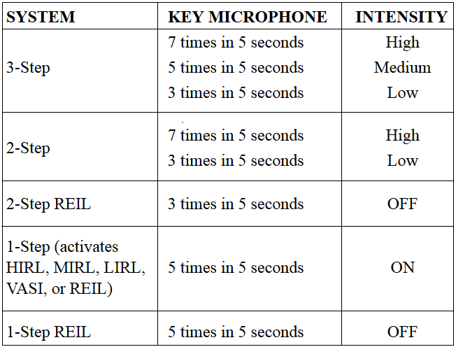
All lighting is illuminated for 15 minutes from the most recent time of activation and may not be extinguished before the end of the 15 minute period (except for 1-step and 2-step REILs, which may be turned off when desired by keying the mike 5 or 3 times respectively)
Suggested use is to always initially key the mike 7 times; this assures that all controlled lights are turned on to the maximum available intensity
If desired, adjustment can then be made, where the capability is provided, to a lower intensity (or the REIL turned off) by keying 5 and/or 3 times
Due to the close proximity of airports using the same frequency, radio-controlled lighting receivers may be set at a low sensitivity, requiring the aircraft to be relatively close to activate the system
Consequently, even when lights are on, always key mike as directed when overflying an airport of intended landing, on downwind, or just before entering the final segment if flying an approach
This will ensure the aircraft is close enough to activate the system and a full 15-minutes lighting duration is available
Do now allow the lights to turn off while you are on a short final!
Approved lighting systems may be activated by keying the mike (within 5 seconds) as indicated in [Figure 3]
Runways With Approach Lighting
Runways With Approach Lighting
Runways Without Approach Lighting
Runways Without Approach Lighting
For all public-use airports with FAA standard systems, the Chart Supplement U.S. contains the types of lighting, runway, and the frequency that is used to activate the system. Airports with IAPs include data on the approach chart identifying the light system, the runway on which they are installed, and the frequency that is used to activate the system
Although the CTAF is used to activate the lights at many airports, other frequencies may also be used. The appropriate frequency for activating the lights on the airport is provided in the Chart Supplement U.S. and the standard instrument approach procedures publications. It is not identified on the sectional charts
Where the airport is not served by an IAP, it may have either the standard FAA-approved control system or an independent type system of different specifications installed by the airport sponsor. The Chart Supplement U.S. contains descriptions of pilot-controlled lighting systems for each airport having other than FAA-approved systems and explains the type of lights, method of control, and operating frequency in clear text
Radio Control System
Airport/Heliport Beacons:
Airport and heliport beacons help identify airports/heliports during low-light conditions
They have a vertical light distribution to make them most effective from one to ten degrees above the horizon; however, they can be seen well above and below this peak spread
The beacon may be an omnidirectional capacitor-discharge device, or it may rotate at a constant speed, which produces the visual effect of flashes at regular intervals
Flashes may be one or two colors alternately
The total number of flashes are:
24-30 flashes per minute for airports, landmarks, and points on federal airways
30-45 flashes per minute for heliports
Most effective from 1° to 10° above the horizon, visible typically at 40nm
It may be an omnidirectional capacitor-discharge device, or it may rotate at a constant speed, providing the visual effect of a flashing light
Operation of the beacon during the day may indicate airport conditions are less than VFR
This means SVFR or IFR is required for takeoff, landings, and flight in the traffic pattern
The colors and color combinations of beacons are: [Figure 3]
White and Green: Lighted land airport
*Green alone: Lighted land airport
White and Yellow: Lighted water airport
*Yellow alone: Lighted water airport
*Green alone or yellow alone is used only in connection with a white-and-green or white-and-yellow beacon display, respectively
Green, Yellow, and White: Lighted heliport
Military airport beacons flash alternately white and green but are differentiated from civil beacons by dual-peaked (two quick) white flashes between the green flashes
In Class B, Class C, Class D, and Class E surface areas, operation of the airport beacon during the hours of daylight often indicates that the ground visibility is less than that of VFR (less than 3 miles and/or the ceiling is less than 1,000'
Pilots should not rely solely on the operation of the airport beacon to indicate if weather conditions are IFR or VFR
At some locations with operating control towers, ATC personnel turn the beacon on or off when controls are in the tower, while in many airports, the airport beacon is turned on by a photoelectric cell or time clocks, and ATC personnel cannot control them
There is no regulatory requirement for daylight operation, so it is the pilot's responsibility to comply with proper preflight planning as required by 14 CFR Section 91.103
Various Airport Beacon Patterns
Obstruction Lights:
Catenary Lighting
Obstructions are marked and lit to warn airmen of their presence during daytime and nighttime conditions
Aviation Red Obstruction Lights:
During daylight hours, aviation orange and white paint is used for marking
During nighttime operation, a flashing red light bacon indicates the marking of an en-route obstruction (20 to 40 flashes per minute)
Steady red light indicates an obstruction in the terminal area
Medium-Intensity Flashing White Obstruction Lights:
Medium-intensity flashing white obstruction lights may be used during daytime and twilight with automatically selected reduced intensity for nighttime operation
When this system is used on structures 500 feet (153m) AGL or less in height, other methods of marking and lighting the structure may be omitted
Aviation orange and white paint is always required for daytime marking on structures exceeding 500' AGL
Not normally installed on structures less than 200' AGL
Medium intensity omnidirectional flashing white lighting system provides conspicuity both day and night on catenary support structures
The unique sequential/simultaneous flashing light system alerts pilots of the associated catenary wires
High-Intensity White Obstruction Light:
Flashing high-intensity white lights during daytime with reduced intensity for twilight and night-time operation
When this type of system is used, the marking of structures with red obstruction lights and aviation orange and white paint may be omitted
High-intensity flashing white lights are also employed to identify tall structures, such as chimneys and towers, as obstructions to air navigation
The lights provide a 360° coverage from the structure at 40 flashes per minute and consist of from one to seven levels of lights depending upon the height of the structure
Where more than one level is used, the vertical banks flash simultaneously
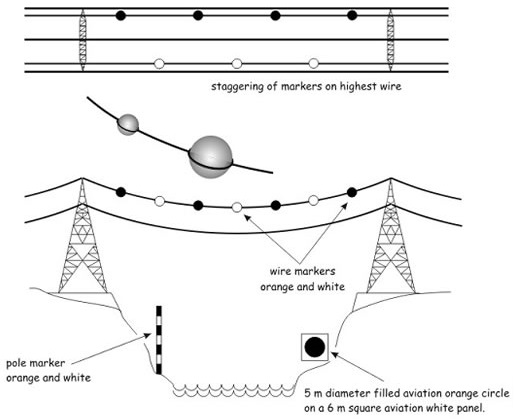
High-intensity flashing white lights are being used to identify some supporting structures of overhead transmission lines located across rivers, chasms, gorges, etc.
These lights flash in a middle, top, and lower light sequence at approximately 60 flashes per minute
The top light is normally installed near the top of the supporting structure, while the lower light indicates the approximate lower portion of the wire span
The lights are beamed toward the companion structure and identify the area of the wire span
Dual Lighting:
A combination of flashing aviation red beacons and steady burning aviation red lights for nighttime operation, and flashing high-intensity white lights for daytime operation
Aviation orange and white paint may be omitted
Catenary Lighting:
Lighted markers are available for increased night conspicuity of high-voltage transmission line catenary wires
Lighted markers provide conspicuity both day and night
Catenary Lighting
LED Lighting Systems:
Certain Light-Emitting Diodes (LEDs) fall outside the combined visible and near-infrared spectrum of night vision goggles (NVGs) and thus will not be visible to a flightcrew using NVGs
The FAA changed specifications for LED-based red obstruction lights to make them visible to pilots using certain NVG systems; however, other colors may not be visible
It is recommended that air carriers/operators-including Part 91 operators-who use NVGs incorporate procedures into manuals and/or standard operating procedures (SOPs) requiring periodic, unaided scanning when operating at low altitudes and when performing a survey of landing areas
Runway Status Light (RWSL) System:
Runway Status Light System
RWSL is a fully automated system that provides runway status information to pilots and surface vehicle operators to clearly indicate when it is unsafe to enter, cross, takeoff from, or land on a runway
The RWSL system processes information from surveillance systems and activates Runway Entrance Lights (REL) and Takeoff Hold Lights (THL) per the position and velocity of the detected surface traffic and approach traffic
REL and THL are in-pavement light fixtures that are directly visible to pilots and surface vehicle operators
RWSL is an independent safety enhancement that does not substitute for or convey an ATC clearance. Clearance to enter, cross, takeoff from, land on, or operate on a runway must still be received from ATC
Although ATC has limited control over the system, personnel do not directly use and may not be able to view light fixture activations and deactivations during the conduct of daily ATC operations
ATC can adjust the intensity and can turn off the system, but that's about it
Aircraft will depart the gate or parking area with the transponder "ON" and will leave it there until the flight is terminated
Runway Entrance Lights:
Flush-mounted, in-pavement, unidirectional fixtures that are parallel and focused along the taxiway centerline and directed toward the pilot (and surface vehicle operators) at the hold line
An array of REL lights includes the first light at the hold line followed by a series of evenly spaced lights to the runway edge; one additional light at the runway centerline is in line with the last two lights before the runway edge
When activated, the red lights indicate that there is high-speed traffic on the runway or there is an aircraft on final approach within the activation area
Operating Characteristics for Departing Aircraft:
When a departing aircraft reaches a site adaptable speed of approximately 30 knots, all taxiway intersections with REL arrays along the runway ahead of the aircraft will illuminate
As the aircraft approaches a REL equipped taxiway intersection, the lights at that intersection extinguish approximately 3 to 4 seconds before the aircraft reaches it
This allows controllers to apply "anticipated separation" to permit ATC to move traffic more expeditiously without compromising safety
After the aircraft is declared "airborne" by the system, all REL lights associated with this runway will extinguish
Operating Characteristics for Arriving Aircraft:
When an aircraft on final approach is approximately 1 mile from the runway threshold, all sets of taxiway REL light arrays that intersect the runway illuminate
The distance is adjustable and can be configured for specific operations at particular airports
Lights extinguish at each equipped taxiway intersection approximately 3 to 4 seconds before the aircraft reaches it to apply anticipated separation until the aircraft has slowed to approximately 80 knots (site adjustable parameter)
Below 80 knots, all arrays that are not within 30 seconds of the aircraft's forward path are extinguished
Once the arriving aircraft slows to approximately 34 knots (site adjustable parameter), it is declared to be in a taxi state, and all lights extinguish
A pilot at or approaching the hold line to a runway will observe RELs illuminate and extinguish in reaction to an aircraft or vehicle operating on the runway or an arriving aircraft operating less than 1 mile from the runway threshold
When a pilot observes the red lights of the REL, that pilot will stop at the hold line or remain stopped
The pilot will then contact ATC for resolution if the clearance is in conflict with the lights
Should pilots note illuminated lights under circumstances when remaining clear of the runway is impractical for safety reasons (for example, aircraft is already on the runway), the crew should proceed according to their best judgment while understanding the illuminated lights indicate the runway is unsafe
Contact ATC at the earliest possible opportunity
Runway Status Light System
Takeoff Hold Lights:
Flush-mounted, in-pavement, unidirectional light fixtures in a double longitudinal row aligned on either side of the runway centerline lighting
Fixtures are focused toward the arrival end of the runway at the "line up and wait" point
THLs extend for 1,500 feet in front of the holding aircraft, starting at a point 375 feet from the departure threshold
Illuminated red lights provide a signal to an aircraft in position for takeoff or rolling that it is unsafe to takeoff because the runway is occupied or about to be occupied by another aircraft or ground vehicle
Two aircraft, or a surface vehicle and an aircraft, are required for the lights to illuminate. The departing aircraft must be in position for takeoff or beginning takeoff roll
Another aircraft or a surface vehicle must be on or about to cross the runway
THLs will illuminate for an aircraft in position for departure or departing when there is another aircraft or vehicle on the runway or about to enter the runway
Once that aircraft or vehicle exits the runway, the THLs extinguish
A pilot may notice the lights extinguish before the downfield aircraft or vehicle are completely clear of the runway but still moving. Like RELs, THLs have an "anticipated separation" feature
When the THLs extinguish, this is not clearance to begin a takeoff roll. All takeoff clearances will be issued by ATC
What a pilot would observe:
A pilot in position to depart from a runway or has begun takeoff roll will observe THLs illuminate in reaction to an aircraft or vehicle on the runway or entering or crossing it
Lights will extinguish when the runway is clear
A pilot may observe several cycles of illumination and extinguishing depending on the amount of crossing traffic
Pilot Actions:
When a pilot observes the red light of the THLs, the pilot should safely stop if it's feasible or remain stopped
The pilot must contact ATC for resolution if any clearance is in conflict with the lights
Should pilots note illuminated lights while on takeoff roll and under circumstances when stopping is impractical for safety reasons, the crew should proceed according to their best judgment while understanding the illuminated lights indicate that continuing the takeoff is unsafe
Contact ATC at the earliest possible opportunity
Pilot Actions:
When operating at airports with RWSL, pilots will operate with the transponder/ADS-B "On" when departing the gate or parking area until it is shut down upon arrival at the gate or parking area
This ensures interaction with the FAA surveillance systems such as ASDE-X/Airport Surface Surveillance Capability (ASSC), which provide information to the RWSL system
Pilots must always inform the ATCT when they have stopped due to an RWSL indication that is in conflict with ATC instructions
Pilots must request clarification of the taxi or takeoff clearance
Never cross over illuminated red lights
Under normal circumstances, RWSL will confirm the pilot's taxi or takeoff clearance previously issued by ATC
If RWSL indicates that it is unsafe to takeoff from, land on, cross, or enter a runway, immediately notify ATC of the conflict and re-confirm the clearance
Do not proceed when lights have extinguished without an ATC clearance
RWSL verifies an ATC clearance; it does not substitute for an ATC clearance
Never land if PAPI continues to flash
Execute a go-around and notify ATC
ATC Control of RWSL System:
Controllers can set in-pavement lights to one of five (5) brightness levels to assure maximum conspicuity under all visibility and lighting conditions
REL and THL subsystems may be independently set
System lights can be disabled should RWSL operations impact the efficient movement of air traffic or contribute, in the opinion of the assigned ATC Manager, to unsafe operations
REL and THL light fixtures may be disabled separately
Whenever the system or a component is disabled, a NOTAM must be issued, and the Automatic Terminal Information System (ATIS) must be update
FAA Safety Team Runway Safety Tips for Pilots & Airport Drivers:
Runway Status Lights (RWSL) tell pilots and vehicle operators to stop when runways are unsafe. The in-pavement runway and taxiway lights automatically turn red when other traffic makes entering, crossing, or beginning takeoff dangerous. The lights provide direct, immediate alerts and require no input from controllers. Runway Status Lights are operational at 20 airports across the U.S.
Here are some tips for when you encounter RWSL:
When operating at airports with RWSL, keep your transponder on "ALT"
Never cross over illuminated red lights
Only proceed when lights have been extinguished if you have received an ATC clearance. RWSL verifies a clearance but does not substitute for one
When holding short of a runway, stop before the hold short markings and associated signs
When clearing a runway, taxi completely across the hold short markings, ensuring your entire aircraft has cleared the hold short line. This ensures you have exited the Runway Safety Area
If you are part of a flight operation, review SAFO 11009 and SAFO 17011
Check out the FAA RWSL Video, enhanced Airport Diagrams, and other resources here: www.faa.gov/air_traffic/technology/rwsl
Runway Lights:
Threshold Lights:
Threshold lights mark the beginning of the landing surface
They consist of four or more green lights, two on each side of the runway
Runway End Identifier Lights (REIL):
Runway End Identifier Lights are installed to provide rapid and positive identification of the approach end of a runway
They consist of synchronized flashing lights located laterally on each side of the threshold, which may be either omni (facing all areas) or unidirectional (facing the approach area)
Helps identify the runway when it is surrounded by other lighting, lacks contrast with surrounding terrain, or during periods of reduced visibility
Runway Edge Light Systems:
Runway edge lights are used to outline runway edges during darkness or restricted visibility
Should define the usable runway area, AC-150
Intensity Classification:
HIRL:
High-Intensity Runway Lights
MIRL:
Medium-Intensity Runway Lights
LIRL:
Low-Intensity Runway Lights
HIRL and MIRL have variable intensities, while LIRL does not
The runway edge lights are white except on instrument runways; yellow replaces white on the last 2,000' or half, whichever is less, to form a caution zone for landings
The lights marking the ends of the runway emit red light toward the runway to indicate the end of the runway to a departing aircraft and emit green outward from the runway end to indicate the threshold to landing aircraft
In-Runway Lighting:
Runway Centerline Lighting System:
Runway Centerline Lighting Systems (RCLS') are installed on some precision approach runways to facilitate landing under adverse visibility conditions
RCLS are spaced at 50' intervals along the centerline markings, offset to the side of the centerline closest to the terminals
When viewed from the landing threshold, the runway centerline lights are white until the last 3,000' when they alternate red and white for 2,000' and eventually red at 1,000'
Touchdown Zone Lights:
Touchdown Zone Lights (TDZL) are installed on some precision approach runways to indicate the touchdown zone during adverse visibility
TDZLs consist of two rows of transverse light bars disposed symmetrically about the runway centerline
Steady burning white lights, which start 100' beyond the landing threshold, extend to 3,000' or half the runway length, whichever is less
Taxiway Centerline Lead-Off Lights:
Installed to provide visual guidance to persons exiting the runway
They are color-coded to warn pilots and vehicle drivers that they are within the runway environment or instrument landing system (ILS) critical area, whichever is more restrictive
Alternate green and yellow lights are installed, beginning with green, from the runway centerline to one centerline light position beyond the runway holding position or ILS critical area holding position
Taxiway Centerline Lead-On Lights:
Installed to provide visual guidance to persons entering the runway
They are color-coded to warn pilots and vehicle drivers that they are within the runway environment or instrument landing system (ILS) critical area, whichever is more conservative
The fixtures used for lead-on lights are bidirectional, i.e., one side emits light for the lead-on function while the other side emits light for the lead-off function
Any fixture that emits yellow light for the lead-off function must also emit yellow light for the lead-on function
Consist of a row of pulsating white lights installed across the runway at the hold short point
They will be on any time LAHSO are in effect, but off when not in effect
Taxiway Lights:
Taxiway Lighting
Taxiway Edge Lights:
Outline edges of taxiways during periods of darkness or restricted visibility
They are omnidirectional steady blue lights [Figure 7]
At some airports, they may be adjusted at the pilot's request or when deemed necessary by the controller
Taxi Centerline Lights:
Facilitate ground traffic under low visibility conditions by illuminating the taxiway centerline
They are located along the taxiway centerline in a straight line on straight portions, on the centerline of curved portions, and along designated taxiing paths in portions of runways, ramps, and apron areas
They are omnidirectional steady green light [Figure 5]
Clearance Bar Lights:
Installed at holding positions to increase the visibility of the holding position
They may also be installed to indicate the location of an intersecting taxiway during periods of darkness
Consists of three in-pavement steady burning yellow lights
Runway Guard Lights:
Runway guard lights are installed at taxiway/runway intersections
Enhances visibility of taxiway/runway intersections during reduced visibility
Consists of either a pair of elevated flashing yellow lights on either side of the taxiway or a row of in-pavement yellow lights across the entire taxiway at the runway holding marking
Some airports may have a row of three or five in-pavement yellow lights installed at taxiway/runway intersections, which should not be confused with clearance bar lights described above
Stop Bar Lights:
Used to confirm ATC clearance to enter or cross the active runway during periods of low visibility (below 1,200 ft Runway Visual Range)
Consists of a row of red, unidirectional, steady in-pavement lights installed across the taxiway at the runway holding position and elevated steady burning red lights on each side
Operated in conjunction with the taxiway centerline lead-on lights, which extended from the stop bar toward the runway
Following the ATC clearance to proceed, the stop bar is turned off, and the lead-on lights are turned on
The lights reset automatically by a sensor or backup timer
Pilots should never cross a red illuminated stop bar even if cleared
If, after crossing a stop bar, the taxiway lead-on lights inadvertently extinguish, pilots should hold their position and contact ATC
Approach Lighting System:
The Approach Lighting System, or ALS, provides the basic means to transition from instrument flight to visual flight for landing
ALS are illuminated during hours of darkness and/or when the visibility is less than that required for visual flight rules
Although their purpose never changes, there are different types of systems a pilot may encounter:
MALSR:
Medium Intensity Approach Lighting System With Runway Alignment Indicator Lights
SSALR:
Simplified Short Approach Light System With Runway Alignment Indicator Lights
MALSF:
Medium Intensity Approach Lighting System With Sequenced Flashers
SSALF:
Simplified Short Approach Light System With Sequenced Flashers
ALSF-1:
Approach Lighting System with Sequence Flashing Lights (ALSF-1)
ALSF-2:
Approach Lighting System with Sequence Flashing Lights (ALSF-2)
REIL:
Runway End Identifier Lights
ODALS:
Omni-directional Approach Lighting System
Configuration of signal lights starting at the threshold and extending into the approach area
2,400-3000' for a precision, instrument runway
1,400-1,500' for a non-precision, instrument runway
Some of these systems include sequenced flashing lights, which appear to the pilot as a ball of light traveling toward the runway at high speed (twice a second)
The NTSB determines the probable cause(s) of this accident to be: The pilot's poor preflight planning, during which he failed to verify the proper procedure to activate the runway lights; his inability to locate the airport without lighting; and the airplane's subsequent low-fuel state as he circled looking for the airport, which necessitated a precautionary off-airport landing, during which the nose landing gear separated
Conclusion:
May request lights be turned on or off, and some lights have intensity control to the Air Traffic Control Tower
Variable lighting is used to save the city from paying for electricity some money when no one is using the airport
Operational requirements dictate the sophistication and configuration of the approach light system for a particular runway
Be careful not to confuse Airport/Heliport Beacons with Aeronautical Light Beacons, which are a function of navigation
Be aware of distractions when flying over urban areas, as flashes of lights through buildings can sometimes give the appearance of light beacons
As obvious as it sounds, realize radio-controlled lighting does not work if the aircraft does not have a radio
Pilot-controlled lighting is a compromise between energy savings and lighting availability, but remember its use requires a radio leaving aircraft with or aircraft experiencing electrical issues without the option to use
REMEMBER: after 15 minutes the lights turn off, do now allow this to happen while you are on a short final!
Resources for specific airports (diagrams, wildlife, accident statistics, etc.) are also available at https://www.faa.gov/airports/