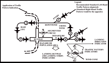
Traffic Pattern:
- The traffic pattern is divided into legs which form a rectangle
- Legs define a phase of flight associated with takeoff, landing, or closed pattern touch and go operations
Upwind leg:
- A flight path parallel to the landing runway in the landing direction
- This leg is the ground path flown immediately after takeoff
Crosswind leg:
- A flight path at right angles to the landing runway off its takeoff end
- The direction of the crosswind leg (left or right turn) is dictated by the airport publications or tower
Downwind leg:
- A flight path parallel to the landing runway in the opposite direction of landing
- While it is the longest leg, it requires the most vigilance for traffic entering and departing
Base leg:
- A flight path at right angles to the landing runway off its approach end and extending from the downwind leg to the intersection of the extended runway centerline
Final Approach:
- A flight path in the direction of landing along the extended runway centerline from the base leg to the runway
- Before touching down, check for waive-off lights if present, or light signals from tower
Departure leg:
- The flight path that begins after takeoff and continues straight ahead along the extended centerline, continuing to a point at least 1/2 mile beyond the runway and within 300' of traffic pattern
- May exit 45° off in the direction of the pattern turns as well
Traffic Pattern Altitude:
- Most airport patterns extend from 600 to 1,500' Above Ground Level (AGL)
- Military turbojet aircraft may extend the pattern up to 2,500' AGL
- Standard traffic pattern is 1,000' AGL
- Standard turbine pattern is 1,500' AGL
- Standard break is at 1,100' AGL
- Standard Naval pattern is at 800' AGL
- Standard carrier break is at 800' AGL
- Standard carrier pattern is at 600' AGL
- Unless otherwise required by the applicable distance from clouds (FAR 91.155) or operations, pilots should maintain traffic pattern altitude
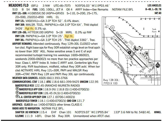
- Traffic patterns are left turns by standard, unless ATC or the Chart Supplement U.S. states otherwise, as shown in Meadows Field below, under RWY 30R and 12R with the text "Rgt tfc"
Touch and Go Procedure:
WARNING:
All procedures are GENERALIZED.
Always fly per Pilot Operating Handbook procedures,
observing any relevant Standard Operating Procedures (SOPs)
- Complete the appropriate landing procedure
- After the nose wheel is down and directional control is maintained, call out, "Flaps Identified" and wait for Instructor's Response, "Flaps Verified" and then set flaps
- Reset the pitch trim as required
- Smoothly and continuously apply full throttle, maintaining directional control and runway centerline with rudder pedals
- Check engine instruments and tachometer (RPM)
- As appropriate, call out, "Engine Instruments in the Green, Airspeed Alive"
- At Vr call out "Vr, Rotate" and increase control yoke back pressure to pitch up until the top of the glare shield meets the horizon
- After liftoff, establish and maintain Vy while maintaining the flight path over the runway centerline
- Trim as necessary
- With a positive rate of climb and no available landing area remaining, depress the brake pedals and call out "Positive Climb, Gear up (as appropriate)"
- Incrementally retract the flaps
- During the climb out (no less than 200' AGL), lower the nose momentarily to ensure that the airspace ahead is clear, and then reestablish and maintain Vy, mainlining the flight path over the extended runway centerline
- Trim as necessary
- At 500' AGL, lower the pitch to establish and maintain cruise climb
- Maintain Vy if climb performance warrants
- Execute a departure procedure, or remain in the traffic pattern, as appropriate
- If remaining in the traffic pattern, commence turn to crosswind leg beyond the departure end of the runway within 300' of pattern altitude
- Continue straight out for at least 2 miles before turning on course, or, after reaching pattern altitude, exit the pattern with a 45° turn in the direction of the traffic pattern
- Complete the Climb Flow/Checklist, when appropriate
- If practical, monitor the frequency for 10 NM to monitor for other traffic
- In the interest of reducing radio communications, it is not required to request a frequency change when outside of the controlled airspace; however within, it still is
Keys to Traffic Pattern Operations:
- Enter pattern in level flight, abeam midpoint of the runway, at pattern altitude (1,000' AGL is recommended pattern altitude unless established otherwise...)
- Try not to enter the pattern on base/final even if that is the quickest as it does not afford you a look at the runway until you're on final
- Maintain pattern altitude until abeam approach end of the landing runway on downwind leg
- Complete turn to final at least 1/4 mile from the runway
- Continue straight ahead until beyond departure end of runway
- If remaining in the traffic pattern, commence turn to crosswind leg beyond the departure end of the runway within 300' of pattern altitude
- If departing the traffic pattern, continue straight out, or exit with a 45° turn (to the left when in a left-hand traffic pattern; to the right when in a right-hand traffic pattern) beyond the departure end of the runway, after reaching pattern altitude
- Do not overshoot final or continue on a track, which will penetrate the final approach of the parallel runway
- Do not continue on a track, which will penetrate the departure path of a parallel runway
- Maintain approximately 1/2 a mile distance from the runway when on downwind
- Distance from the airport can be referenced by landmarks or using runway lengths for perspective
Undershooting/Overshooting:
-
Undershooting:
-
Overshooting:
Unexpected Maneuvers inside the Pattern:
- Several incidents in the vicinity of controlled airports were caused by aircraft executing unexpected maneuvers
- Certain instances may call for quick maneuvers, others may not, its the Pilot-In-Command (PIC) who is directly responsible for the operation of the aircraft
- A controller can anticipate minor maneuvers such as an S-turn for spacing, however, a 360° turn should never be executed when in the pattern (or under radar services), unless in an emergency
- Such maneuvers can cause chain reactions which may result in problems later if not immediately causing danger
- Ultimately, if required, notify ATC as soon as possible
Segmented Circle:
- At those airports without an operating control tower, a segmented circle visual indicator system, if installed, is designed to provide traffic pattern information
- The segmented circle will be located in a position affording maximum visibility to pilots in the air and on the ground and providing a centralized location for other elements of the system
- The segmented circle consists of several indicators including:
- Wind direction indicator
- Landing direction indicator
- Landing strip indicator
- Traffic pattern indicator
-
Wind Direction Indicator:
- A wind cone, wind sock, or wind tee installed near the operational runway to indicate wind direction. The large end of the wind cone/wind sock points into the wind as does the large end (cross bar) of the wind tee. In lieu of a tetrahedron and where a wind sock or wind cone is collocated with a wind tee, the wind tee may be manually aligned with the runway in use to indicate landing direction. These signaling devices may be located in the center of the segmented circle and may be lighted for night use. Pilots are cautioned against using a tetrahedron to indicate wind direction
-
Landing Direction Indicator:
- A tetrahedron is installed when conditions at the airport warrant its use. It may be used to indicate the direction of landings and takeoffs. A tetrahedron may be located at the center of a segmented circle and may be lighted for night operations. The small end of the tetrahedron points in the direction of landing. Pilots are cautioned against using a tetrahedron for any purpose other than as an indicator of landing direction. Further, pilots should use extreme caution when making runway selection by use of a tetrahedron in very light or calm wind conditions as the tetrahedron may not be aligned with the designated calm-wind runway. At airports with control towers, the tetrahedron should only be referenced when the control tower is not in operation. Tower instructions supersede tetrahedron indications
-
Landing Strip Indicator:
- Installed in pairs as shown in the segmented circle diagram and used to show the alignment of landing strips
-
Traffic Pattern Indicator:
- Arranged in pairs in conjunction with landing strip indicators and used to indicate the direction of turns when there is a variation from the normal left traffic pattern. (If there is no segmented circle installed at the airport, traffic pattern indicators may be installed on or near the end of the runway)
- Preparatory to landing at an airport without a control tower, or when the control tower is not in operation, pilots should concern themselves with the indicator for the approach end of the runway to be used. When approaching for landing, all turns must be made to the left unless a traffic pattern indicator indicates that turns should be made to the right. If the pilot will mentally enlarge the indicator for the runway to be used, the base and final approach legs of the traffic pattern to be flown immediately become apparent. Similar treatment of the indicator at the departure end of the runway will clearly indicate the direction of turn after takeoff
- When two or more aircraft are approaching an airport for the purpose of landing, the pilot of the aircraft at the lower altitude has the right-of-way over the pilot of the aircraft at the higher altitude. However, the pilot operating at the lower altitude should not take advantage of another aircraft, which is on final approach to land, by cutting in front of, or overtaking that aircraft
Touch and Go Airman Certification Standards:
Conclusion:
- Pilots of en route aircraft should be constantly on the alert for other aircraft in traffic patterns and avoid these areas whenever possible
- Increased traffic congestion, aircraft in climb and descent attitudes, and pilot preoccupation with the cockpit duties are some factors that increase the accident potential in the terminal area
- The situation is then further compounded when the weather is marginal
- Pilots must be particularly alert when operating in the vicinity of an airport
- Density altitude, wind conditions, and available runway length and after touchdown must be considered prior to attempting this maneuver as performance will greatly vary with/without an instructor on board
- Consider practicing maneuvers on a flight simulator to introduce yourself to maneuvers or knock off rust
- The AOPA also offers a runway safety course
- Still looking for something? Continue searching:
References:
- Federal Aviation Administration - Pilot/Controller Glossary
- Advisory Circular (90-66) Recommended Standards Traffic Patterns for Aeronautical Operations at Airports without Operating Control Towers
- Aeronautical Information Manual (4-1-9) Traffic Advisory Practices at Airports Without Operating Control Towers
- Aeronautical Information Manual (4-3-1) General
- Aeronautical Information Manual (4-3-2) Airports with an Operating Control Tower
- Aeronautical Information Manual (4-3-3) Traffic Pattern
- Aeronautical Information Manual (4-3-5) Unexpected Maneuvers in the Airport Traffic Pattern
- CFI Notebook.net - Chart Supplement U.S.
- CFI Notebook.net - Aviation Roles
- CFI Notebook.net - Class Echo Airspace
- CFI Notebook.net - Rectangular Course
- Federal Aviation Regulations (91.155) Basic VFR weather minimums