Electrical Components:
- Alternator/Generator
- Battery
- Master/Battery Switch
- Alternator/Generator Switch
- Bus bar, fuses, and circuit breakers
- Voltage regulator
- Ammeter/Loadmeter
- Static Wicks
- Associated electrical wiring
-
Alternator/Generator:
- Alternators and/or Generators are engine-driven power source accessories which supply electric current to the electrical system for in-flight operations while maintaining a sufficient electrical charge on the battery
-
Alternators:
- Alternators rotate a magnetic field inside stationary coils of wires
- Alternators produce sufficient current to operate the entire electrical system, even at slower engine speeds, by producing alternating current, which is converted to direct current
- The electrical output of an alternator is more constant throughout a wide range of engine speeds
- Some aircraft have receptacles to which an external ground power unit (GPU) may be connected to provide electrical energy for starting which can be very useful, especially during cold weather starting
-
Generators:
- In the generator, the conductors are copper wires that are wound around an armature that is bolted to the drive pulley
- As the armature rotates, the copper wires move through a magnetic field that is produced by permanent magnets which produces electrical power
- Generators don't produce rated output until engine rpm is up in the midrange of operation - typically above 1,400 rpm
- Pilots who have experienced the rapid dimming of a landing light as they reduce engine rpm on short final will understand one of the drawbacks of a generator-powered system
- Disadvantages:
- Heavy
- Lower electrical output
- Electrical noise and static that radiate to other avionics
- Require more maintenance than alternators
- Advantages:
- Not sensitive to errant electrical spikes or reversed polarity
- an produce electrical power even if the battery is dead
- Learn more about alternator maintenance, read the AOPA's articles on caring for your alternator and 500-hour inspections
-
Battery:
- Electrical energy stored in a battery provides a source of electrical power for starting the engine and a limited supply of electrical power for use in the event the alternator or generator fails
- Most direct-current generators will not produce a sufficient amount of electrical current at low engine RPM to operate the entire electrical system
- During operations at low engine RPM, the electrical needs must be drawn from the battery, which can quickly be depleted
- Trickle charger (not standard charger) may be beneficial to the battery life
- Some aircraft have two batteries, allowing for offsetting replacement times, but also bring extra connections, wire, etc. which adds complexity
-
Master/Battery Switch:
- The electrical system is turned on or off with a master switch
- This would be the equivalent of turning your car keys to run electrical components without actually starting the car
- Turning the master switch to the ON position provides electrical energy to all the electrical equipment circuits except the ignition system
- Many aircraft are equipped with a battery switch that controls the electrical power to the aircraft in a manner similar to the master switch
-
Alternator/Generator Switch:
- In addition, an alternator switch is installed which permits the pilot to exclude the alternator from the electrical system in the event of alternator failure
- With the alternator half of the switch in the OFF position, the entire electrical load is placed on the battery
- All non-essential electrical equipment should be turned off to conserve battery power
-
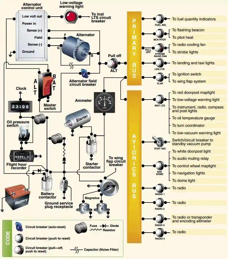
Bus Bar, Fuses, and Circuit Breakers:
- A bus bar is used as a terminal in the aircraft electrical system to connect the main electrical system to the equipment using electricity as a source of power
- This simplifies the wiring system and provides a common point from which voltage can be distributed throughout the system
- Fuses or circuit breakers are used in the electrical system to protect the circuits and equipment from electrical overload
- Spare fuses of the proper amperage limit should be carried in the aircraft to replace defective or blown fuses
- Circuit breakers have the same function as a fuse but can be manually reset, rather than replaced, if an overload condition occurs in the electrical system
- Placards at the fuse or circuit breaker panel identify the circuit by name and show the amperage limit
-
Voltage Regulator:
- A voltage regulator controls the rate of charge to the battery by stabilizing the generator or alternator electrical output
- The generator/alternator voltage output should be higher than the battery voltage
- For example, a 12-volt battery would be fed by a generator/alternator system of approximately 14 volts
- The difference in voltage keeps the battery charged
- Consider backup solutions to panel gauges that can plug into cigarette lighters (if available)
- Ensure the digital voltmeter matches the electrical system (i,e., 12V or 24V)
-
Ammeter/Loadmeter:
-
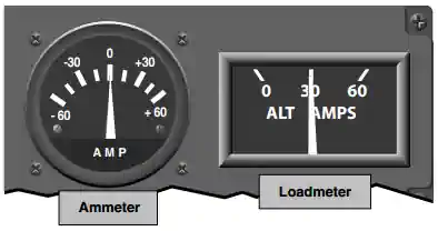
Ammeter:
- Ammeters are designed with the zero point in the center of the face and a negative or positive indication on either side [Figure 2]
- An ammeter is used to monitor the performance of the aircraft electrical system which shows if the alternator/generator is producing an adequate supply of electrical power
- When the pointer of the ammeter is on the plus side, it shows the charging rate of the battery
- A minus indication means more current is being drawn from the battery than is being replaced
- A full-scale minus deflection indicates a malfunction of the alternator/generator
- A full-scale positive deflection indicates a malfunction of the regulator
- In either case, consult the AFM or POH for appropriate action to be taken
- Not all aircraft are equipped with an ammeter-some have a warning light that, when lighted, indicates a discharge in the system as a generator/alternator malfunction
- Refer to the AFM or POH for appropriate action to be taken
- It also indicates whether or not the battery is receiving an electrical charge
-
Loadmeter:
- The loadmeter reflects the total percentage of the load placed on the generating capacity of the electrical system by the electrical accessories and battery [Figure 2]
- When all electrical components are turned off, it reflects only the amount of charging current demanded by the battery
-
-
Static Wicks:
- Aircraft build up static electricity via the friction generated by traveling through the air
- Static wicks are therefore installed to discharge electrical buildup into the atmosphere
- Static wicks control electrical discharge into the atmosphere, isolating noise and preventing it from interfering with aircraft communication equipment
- This discharge prevents buildup which allows for satisfactory operation of on-board navigation and radio communication systems
- Dry air in particular helps insulate electricity discharge making their presence even more useful in winter
- Additionally it is necessary to dissipate static buildup during refueling to prevent a spark and therefore ignition of fuel vapors
- Learn more about static wicks here


Electrical Equipment:
- Equipment that commonly use the electrical system include:
- Aircraft Lights
- Radio Equipment
- Turn Indicator
- Fuel Gauges
- Electric Fuel Pump
- Stall Warning System
- Pitot Heat
- Starting Motor
Associated Electrical Wiring:
- This type of gauge has a scale beginning with zero and shows the load being placed on the alternator/generator
Common Training Aircraft Electrical System Characteristics:
-
Cessna-172:
- 28 Volt DC electrical system
- Powered by 60-amp alternator (belt-driven) and a 24-volt battery (left forward side of firewall)
- Power distribution module (J-box) located on the left forward side of the firewall houses all relays, the alternator control unit, and the external power connector within the module
-
Piper Arrow:
- 14 Volt DC electrical System
- Powered by a 60-amp alternator (belt-driven) and a 12-volt, 35 ampere hour battery
Private Pilot - Electrical System Airman Certification Standards:
Electrical Errors and Malfunctions:
-
Alternator Failure:
- Leading to failure, alternators may cause a whining sound to be picked up on the headset as well as generally under-perform (degraded charging)
- An alternator failure can be recognized by the batteries picking up the electrical load on the aircraft
- The aircraft will continue to fly without the alternator, if that is the only issue
- However, aircraft components such as radios and lights will eventually cease to function
- This means the aircraft will not be legal to fly and may prohibit safe landing at the intended airport due to the loss of radios and transponder
-
Alternator Failure Considerations:
- Alternator failures at night should be considered an emergency in most situations
- Declaring emergency to buys attention and priority handling
- How much battery time you have depends on the health and size of your battery, as well as how quickly you notice and respond to the failure
- Turn off as much as you reasonably can
- Consider turning off nonessential lights, especially non-LED lights
- Pitot heat uses a lot of power, but don't turn it off if you need it
- You can likely turn off one radio, and possibly your transponder if you're not being vectored by ATC
- If you have an iPad you can navigate with, turn off the GPS too
- Keep radio transmissions to a minimum—they're a significant power draw—and consider using a handheld radio proactively
- Turn off autopilots
- Dim the backlighting on glass displays as low as possible. If you have instruments with internal battery backups, understand how to make them switch to their internal batteries if not automatic
- If you need more range than the battery alone will provide, you still have an option:
- Turn off the master switch and fly by iPad or dead reckoning until you're in range of an airport
- Then turn the master back on and you'll have power to spare when you need it most
- This is even an option in IMC on an IFR flight plan
- Let ATC know when and where you plan to turn your radios back on, and they'll provide a frequency to call, and the controllers there will be expecting you
- Save battery for approach phase, including instrument approaches, pilot-controlled lighting, as well as for electric flaps and landing gear
- Tell ATC your plan and ETA before the battery dies so they can look, provide signals, and clear airspace
- Alternator failures at night should be considered an emergency in most situations
-
Low Battery Voltage:
- Insufficient voltage from dead bat may effect an alternator, but especially a generator's ability to charge
Private Pilot - Operation of Aircraft Systems Airman Certification Standards:
- To determine that the applicant exhibits satisfactory knowledge, risk management, and skills associated with the safe operation of systems on the airplane provided for the flight test
- References: FAA-H-8083-2, FAA-H-8083-3, FAA-H-8083-23, FAA-H-8083-25; POH/AFM
- Lesson Plan
Operation of Aircraft Systems Knowledge:
The applicant must demonstrate an understanding of:PA.I.G.K1:
Airplane systems, to include: (Note: If K1 is selected, the evaluator must assess the applicant's knowledge of at least three of the following sub-elements-
PA.I.G.K1a:
Primary flight controls -
PA.I.G.K1a:
Secondary flight controls -
PA.I.G.K1c:
Powerplant and propeller -
PA.I.G.K1d:
Landing gear -
PA.I.G.K1e:
Fuel, oil, and hydraulic -
PA.I.G.K1f:
Electrical -
PA.I.G.K1g:
Avionics -
PA.I.G.K1h:
Pitot-static, vacuum/pressure, and associated flight instruments -
PA.I.G.K1i:
Environmental -
PA.I.G.K1j:
Deicing and anti-icing -
PA.I.G.K1k:
Water Rudders -
PA.I.G.K1l:
Oxygen Systems
-
PA.I.G.K2:
Indications of and procedures for managing system abnormalities or failures
Operation of Aircraft Systems Risk Management:
The applicant demonstrates the ability to identify, assess, and mitigate risks, encompassing:PA.I.G.R1:
Failure to detect system malfunctions or failuresPA.I.G.R2:
Improper management of a system failurePA.I.G.R3:
Failure to monitor and manage automated systems
Operation of Aircraft Systems Skills:
The applicant demonstrates the ability to:PA.I.G.S1:
Operate at least three of the systems listed in K1a through K1l above appropriatelyPA.I.G.S2:
Use appropriate checklists properly
Private Pilot - Systems and Equipment Malfunctions Airman Certification Standards:
- To determine that the applicant exhibits satisfactory knowledge, risk management, and skills associated with system and equipment malfunctions appropriate to the airplane provided for the practical test and analyzing the situation and take appropriate action for simulated emergencies
- FAA-H-8083-2, FAA-H-8083-3; POH/AFM
Systems and Equipment Malfunctions Knowledge:
The applicant must demonstrate an understanding of:-
PA.IX.C.K1:
Partial or complete power loss related to the specific powerplant, including:-
PA.IX.C.K1a:
Engine roughness or overheat -
PA.IX.C.K1b: Carburetor or induction icing
-
PA.IX.C.K1c:
Loss of oil pressure -
PA.IX.C.K1d:
Fuel starvation
-
-
PA.IX.C.K2:
System and equipment malfunctions specific to the airplane, including:-
PA.IX.C.K2a:
Electrical malfunction -
PA.IX.C.K2b:
Vacuum/pressure and associated flight instrument malfunctions -
PA.IX.C.K2c:
Pitot/static system malfunction -
PA.IX.C.K2d:
Electronic flight deck display malfunction -
PA.IX.C.K2e:
Landing gear or flap malfunction -
PA.IX.C.K2f:
Inoperative trim
-
-
PA.IX.C.K3:
Smoke/fire/engine compartment fire -
PA.IX.C.K4:
Any other system specific to the airplane (e.g., supplemental oxygen, deicing) -
PA.IX.C.K5:
Inadvertent door or window opening
Systems and Equipment Malfunctions Risk Management:
The applicant demonstrates the ability to identify, assess, and mitigate risks, encompassing:-
PA.IX.C.R1:
Failure to use the proper checklist for a system or equipment malfunction -
PA.IX.C.R2:
Distractions, loss of situational awareness, or improper task management
Systems and Equipment Malfunctions Skills:
The applicant demonstrates the ability to:-
PA.IX.C.S1:
Describe appropriate action for simulated emergencies specified by the evaluator, from at least three of the elements or sub-elements listed in K1 through K5 above -
PA.IX.C.S2:
Complete the appropriate checklist
Conclusion:
- If you do not already have one, consider purchasing a hand held radio
- Still looking for something? Continue searching: