Altimeter
An accurate sense of altitude is essential for terrain clearance, airspace compliance, and safe flight operations. Understanding the aircraft altimeter and pressure altitude concepts helps pilots interpret how atmospheric pressure changes influence altitude indications in the cockpit.
Aircraft Altimeter Introduction
- An altimeter is a type of barometer which measures the vertical distance to the surface, necessary for a pilot to maintain the desired or assigned altitude during flight.
- Maintaining a current altimeter setting is critical because the atmosphere pressure is never constant.
- That is, in one location the pressure might be higher than the pressure just a short distance away.
- Altimeters function by measuring pressure differences which are displayed in terms of feet (or meters).
- Different types of altimeters measure different types of altitude.
- Altimeters however, are not without their inaccuracies and errors.
- Taking these errors into consideration, a set of cold temperature and altimeter procedures standarize operations under extreme conditions.
- As technology matures, new instrumentation including encoding altimters are better sharing altitude information.
- No matter the case, pilots conduct their preflight actions which include regulatory compliance to mitigate inaccuracies altimeter.
- Altimeter technology has not remain static and the advent of Inertial Reference Units (IRU), Inertial Navigation Systems (INS), and Attitude Heading Reference Systems (AHRS).
- As with any system or instrument, anomalies and malfunctions are possible, requiring detailed knowledge of the indicator and related systems.
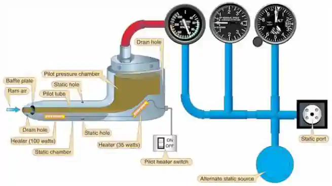
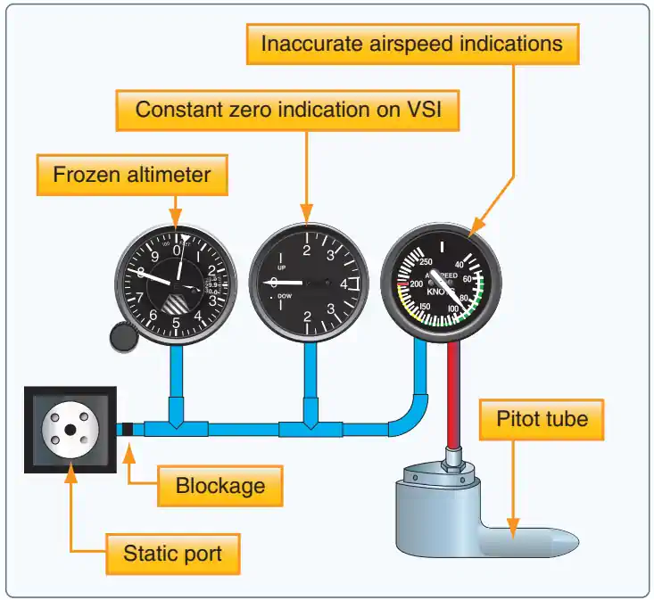
Pitot-Static System
- Pitot Static systems measure and compare air pressures from the Pitot tube and static port
- These measurements display indications for the Airspeed Indicator (ASI), Altimeter, and Vertical Speed Indicators (VSI)
- The system consists of two components:
-
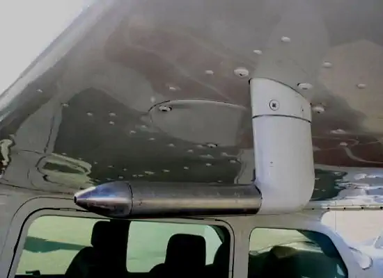
Pitot Tube:
- Invented by Henri Pitot in 1732, the Pitot tube measures fluid flow (air) velocity.
- The device measures ram (forced) air through a small hole in its front.
- The device's placement is often on the front of the aircraft or an airfoil to capture smooth (undisturbed) air. [Figure 1]
- The ram air captured produces an airspeed reading on the airspeed indicator (ASI).
-
Pitot Heat:
- Pitot Tubes are often electrically heated, which can prevent and remove ice accumulation.
- Note that these devices should only be utilized during ground operations when necessary.
- Leaving them on unnecessarily can cause heat to the point of damage/malfunction.
- When airborne, the airflow otherwise cools the device.
-
Static Port:
- Static ports measure ambient still-air atmospheric pressure.
- Typically, ports are flush mounted on the side of the aircraft where air is undisturbed. [Figure 2]
- Some aircraft may utilize heated static ports to mitigate ice.
- Dual ports remove errors due to slips and skids.
- Responsible for Airspeed Indicator, Altimeter, and Vertical Speed Indicators.
- The POH/AFM contains any corrections to the airspeed for the various flaps and landing gear configurations.
-
Alternate Static Source:
- An alternate static air source valve is available for emergencies on some aircraft.
- If the alternate source ports inside the airplane, where static pressure is usually lower than outside, selection may result in the following erroneous instrument indications:
- The altimeter reads higher than normal.
- Indicated airspeed (IAS) reads greater than normal.
- VSI momentarily shows a climb.
- Many POHs provide a correction table and aircraft-specific instructions.
- The alternate static source is not corrected for non-standard pressure (as with an altimeter's Kollsman window).
- Using alternate static sources may impact other instruments that rely on static pressure (i.e., autopilots, TCAS, transponder, etc.).
- Using alternate static sources can also decrease the accuracy beyond the 75 feet recommendation outlined in the Aeronautical Information Manual.

Altimeter Function and Design
- Altimeters exist as a means to indicate the height above a reference, usually mean sea level (MSL) or above ground level (AGL).
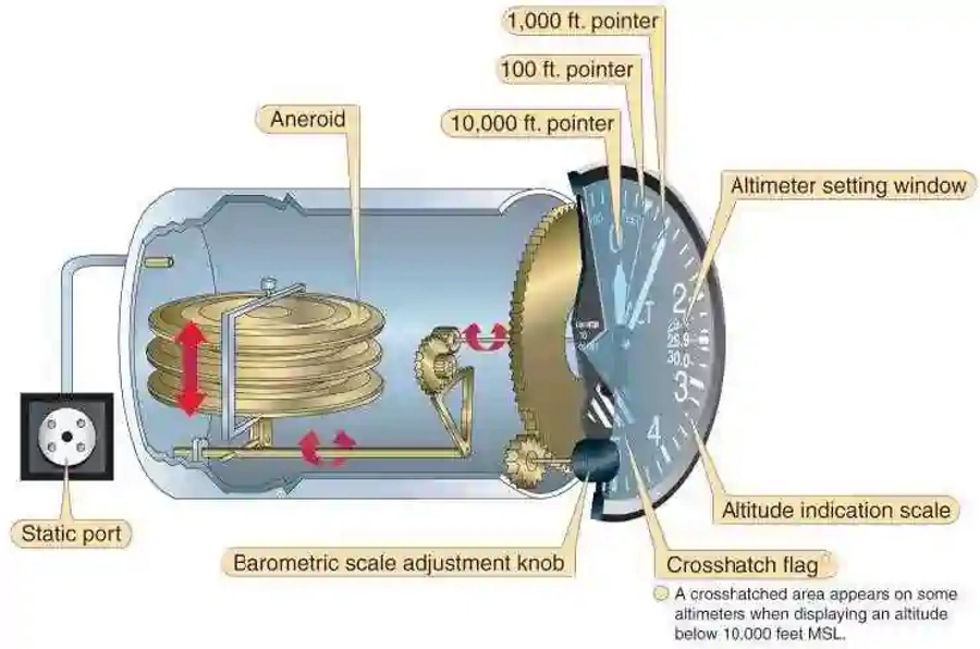
- The device consists of evacuated, corrugated bronze aneroid capsules which connect to needles on the face of the instrument
- As an aircraft increases in altitude the aneroid capsules which are calibrated to 29.92 expand due to decreasing ambient air pressure which moves the needles through gears and linkages to show an increase in altitude
- Conversely, as the aircraft descends, increasing pressure on the capsules causes them to contract while gears and linkages display a decrease in altitude
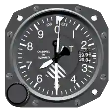
- The altimeter can be calibrated for non-standard pressure (not temperature) by changing the pressure setting in the Kollsman/altimeter setting window [Figure 3]
- Air Traffic Control issues altimeter (pressure) settings to pilots of a local area to ensure pilots use the same reference datum
- Rotating the knob changes both the barometric scale and the altimeter pointers in such a way that a change in the barometric scale of 1" Hg changes the pointer indication by 1,000' which indicates the standard pressure lapse rate
- The setting is set based on the local AWOS/ASOS/ATIS reading
- When set to the local altimeter setting, the altimeter shows height above sea level (true altitude), but not above such land features as hills, mountains, or valleys (absolute altitude)
- If set to the local field elevation prior to takeoff, such as the case with gliders, the altimeter will show height above the ground (absolute altitude), but not above sea level (sea level)
- The altimeter functions like a barometer, detecting pressure differences from a standard (29.92 in-Hg, aka, absolute pressure) using the static system
- A striped segment is visible below 10,000', while above, a mask begins to cover it until 15,000', where it is fully covered
- Stripes start to cover at 10,000' and completely cover at 15,000'
Types of Altimeters
- Different altimeters measure altitude through various methods such as radio, radar, laser, or capacitive technology
-
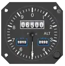
Drum Type:
- These instruments have only one pointer that makes one revolution for every 1,000'
- Each number represents 100' and each mark represents 20'
- A drum, marked in thousands of feet, is geared to the mechanism that drives the pointer
- To read this type of altimeter, first look at the drum to get the thousands of feet, and then at the pointer to get the feet and hundreds of feet
-
Sensitive Altimeter:
- One with an adjustable barometric scale allowing the pilot to set the reference pressure from which the altitude is measured
- This scale is visible in a small window called the Kollsman window
- A knob on the instrument adjusts the scale
- The range of the scale is from 28.00" to 31.00" inches of mercury (Hg), or 948 to 1,050 millibars
-
Absolute Altimeter:
- Also referred to as a radio altimeter, indicating the altitude over objects below based on radio signal pulses
-
Radio Altimeters:
- The radio altimeter (also known as radar altimeter or RADALT) is a safety-critical aircraft system used to determine an aircraft's height above terrain
- It is the only sensor onboard the aircraft capable of providing a direct measurement of the clearance height above the terrain and obstacles
- Information from radio altimeters is essential for flight operations as a main enabler of several safety-critical functions and systems on the aircraft
- The receiver on the radio altimeter is highly accurate because it is extremely sensitive, making it susceptible to radio frequency interference (RFI)
- RFI in the C-band portion of the spectrum could impact the functions of the radio altimeter during any phase of flight-most critically during takeoff, approach, and landing phases
- This could pose a serious risk to flight safety
- Installed radio altimeters normally supply critical height data to a wide range of automated safety systems, navigation systems, and cockpit displays
- Harmful RFI affecting the radio altimeter can cause these safety and navigation systems to operate in unexpected ways and display erroneous information to the pilot
- RFI can interrupt, or significantly degrade, radio altimeter functions-precluding radio altimeter-based terrain alerts and low-visibility approach and landing operations
- Systems of concern include Terrain Awareness Warning Systems (TAWS), Enhanced Ground Proximity Warning Systems (EGPWS), and Traffic Collision Avoidance Systems (TCAS), to name a few
- Pilots of radio altimeter equipped aircraft should become familiar with the radio altimeter's interdependence with the other aircraft systems and expected failure modes and indications that may be associated with harmful interference
- Recognizing interference/anomalies in the radio altimeter can be difficult, as it may present as inoperative or erroneous data
- Pilots need to monitor their automation, as well as their radio altimeters for discrepancies, and be prepared to take action
- Pilots encountering radio altimeter interference/anomalies should transition to procedures that do not require the radio altimeter, and inform Air Traffic Control (ATC)
- In Flight Reports: Pilots should report any radio altimeter anomaly experienced to ATC as soon as practical
- Post Flight Reports: Pilots are encouraged to submit detailed reports of radio altimeter interference/anomalies post flight as soon as practical, by internet via the Radio Altimeter Anomaly Reporting Form at https://www.faa.gov/air_traffic/nas/RADALT_reports/
- The post flight pilot reports of radio altimeter anomalies should contain as much of the following information as applicable:
- Date and time the anomaly was observed;
- Location of the aircraft at the time the anomaly started and ended (e.g., latitude, longitude or bearing/distance from a reference point or navigational aid);
- Magnetic heading;
- Altitude (MSL/AGL);
- Aircraft Type (make/model);
- Flight Number or Aircraft Registration Number;
- Meteorological conditions;
- Type of radio altimeter in use (e.g., make/model/software series or version), if known;
- Event overview;
- Consequences/operational impact (e.g., impacted equipment, actions taken to mitigate the disruption and/or remedy provided by ATC, required post flight pilot and maintenance actions)
- The radio altimeter (also known as radar altimeter or RADALT) is a safety-critical aircraft system used to determine an aircraft's height above terrain
Types of Altitude
- Altitude is a measure of how far you are above a reference point
-
Absolute altitude:
- The height of an aircraft above the terrain over which it is flying.
- Absolute altitude is rarely referred to by it's name, but instead expressed as AGL (above ground level) or HAA, HAT, or TCH (height above airport, height above touchdown, treshold crossing height, etc.).
-
Indicated Altitude:
- After setting the altimeter at the current altimeter setting, this is the uncorrected altitude read directly from that altimeter
-
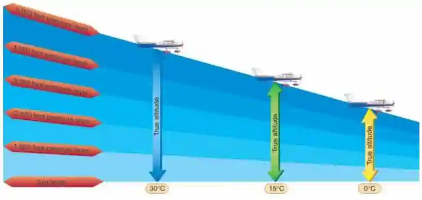
True Altitude:
- Actual aircraft's height above sea level, usually expressed as MSL (mean sea level); all elevations on aeronautical charts are expressed in terms of true altitude
- True altitude varies directly with temperature.
- True altitude increases as outside air temperature increases.
- True altitude decreases as outside air temperature decreases.
- This relationship is due to warm air expanding, causing pressure levels to rise.
-
Pressure Altitude:
- After adjusting the altimeter's setting to 29.92 mb or 1,013.2 mb, this is the altimeter reading that corresponds to the altitude in the standard atmosphere where the pressure is the same as you are
- Calculate pressure altitude
- LAGS: (inversely proportional)
- If the given altimeter setting is less than 29.92, then you ADD to your altitude
- If the given altimeter setting is greater than 29.92, then you SUBTRACT from your altitude
- See more here in the atmosphere section
-
Density Altitude:
- The pressure altitude corrected for temperature variations
- This is most important to takeoff and climb performance of an aircraft
- Calculate density altitude
- See more here in the atmosphere section
-
GPS Altitude:
- GPS Altitude is a measure take from, and therefore in reference to, the GPS Satellite Constellation
- GPS measures altitude above the earth using the World Geodetic System (WGS84)
- GPS altitude used on many electronic kneeboards will not match the altimeter
- Since pressure readings passed to pilots are taken on the ground, atmospherics will guarantee a disparity between GPS altitude and pressure altitude as altitude increases
- Although GPS altitude can be highly accurate, it is usually not referenced while in flight
- This ensures all aircraft are using the same reference, and any error from pressure settings is generally shared across all aircraft
Altimeter Inaccuracies and Errors
- There are several factors which can impact an aircraft altimeter, inducing inaccuracies and errors
- The standard altimeter 29.92 inches Mercury ("Hg.) setting at the higher altitudes eliminates station barometer errors, some altimeter instrument errors, and errors caused by altimeter settings derived from different geographical sources
- Extreme caution must be exercised when operating in proximity to obstructions or terrain, especially in cold temperatures that cause a large differential between the standard day temperature and actual temperature.
- The same is true when operating at low pressures.
- Low temperature and pressures can cause serious errors that result in the aircraft being significantly lower than the indicated altitude
- Pilots should apply corrections for static pressure systems and/or instruments, if appreciable errors exist
-
Instrument Errors:
- Manufacturing and installation specifications, along with 14 CFR Part 43, Appendix E requirement for periodic tests and inspections, helps reduce mechanical, elastic, temperature, and installation errors. (See Instrument Flying Handbook.) Scale error may be observed while performing a ground altimeter check using the following procedure:
- Set the current reported airfield altimeter setting on the altimeter setting scale
- Read the altitude on the altimeter
- The altitude should read the known field elevation if you are located on the same reference level used to establish the altimeter setting
- If the difference from the known field elevation and the altitude read from the altimeter is plus or minus 75 feet or greater, the accuracy of the altimeter is questionable and the problem should be referred to an appropriately rated repair station for evaluation and possible correction
- Note that use of alternate static sources can increase any error to exceed the 75 feet requirement
-
Inherent Altimeter Errors:
- When the aircraft is flying in air that is warmer than standard, the air is less dense and the pressure levels are farther apart
- When the aircraft is flying at an indicated altitude of 5,000', the pressure level for that altitude is higher than it would be in air at standard temperature, and the aircraft is higher than it would be if the air were cooler
- If the air is colder than standard, it is denser and the pressure levels are closer together
- When the aircraft is flying at an indicated altitude of 5,000', its true altitude is lower than it would be if the air were warmer
- When the aircraft is flying in air that is warmer than standard, the air is less dense and the pressure levels are farther apart
-
Mechanical Errors:
- Errors with the instrument itself
- If the indication checked during preflight is off by more than 75' from the surveyed elevation, the instrument should be referred to a certificated instrument repair station for recalibration
- Differences between ambient temperature and/or pressure causes an erroneous indication on the altimeter
- Manufacturing and installation specifications, along with 14 CFR Part 43, Appendix E requirement for periodic tests and inspections, helps reduce mechanical, elastic, temperature, and installation errors. (See Instrument Flying Handbook.) Scale error may be observed while performing a ground altimeter check using the following procedure:
-
Position Error:
- Most aircraft do not have the capability of setting an altimeter above 31.00 in-Hg or below 28.00 in-Hg
- For aircraft with the capability of setting the current altimeter setting and operating into airports with the capability of measuring the current altimeter setting, no additional restrictions apply
- Aircraft Static Pressure Systems, also known as position error, may impact the accuracy of the pressure collected
- Most aircraft do not have the capability of setting an altimeter above 31.00 in-Hg or below 28.00 in-Hg
- A sensitive altimeter is designed to indicate standard changes from standard conditions, but most flying involves errors caused by non-standard conditions and the pilot must be able to modify the indications to correct for these errors
-
Non-Standard Temperature:
- Temperature has an effect on the accuracy of barometric altimeters, indicated altitude, and true altitude
- When the column of air is warmer than standard, you are higher than your altimeter indicates
- Subsequently, when the column of air is colder than standard, you are lower than indicated
- Standard temperature at sea level is 15 degrees Celsius (59° Fahrenheit)
- The temperature gradient from sea level is minus 2° Celsius (3.6° Fahrenheit) per 1,000'
- See the atmosphere page for more
- Pilots should apply corrections for static pressure systems and/or instruments, if appreciable errors exist
- The temperature gradient from sea level is minus 2° Celsius (3.6° Fahrenheit) per 1,000'
- The crucial values to consider are standard temperature versus the ambient (at altitude) temperature and the elevation above the altitude setting reporting source
- It is these "differences" and their magnitude that determine the error in indicated altitude
- Unless the airport requires a cold weather adjustment, this error may not be noticeable, if not for the easy reference to GPS altitude in modern day cockpits with which to compare
- When flying into a cooler air mass while maintaining a constant indicated altitude, you are losing true altitude. However, flying into a cooler air mass does not necessarily mean you will be lower than indicated if the difference is still on the plus side. For example, while flying at 10,000 feet (where STANDARD temperature is +5 degrees Celsius (C)), the outside air temperature cools from +5 degrees C to 0 degrees C, the temperature error will nevertheless cause the aircraft to be HIGHER than indicated. It is the extreme "cold" difference that normally would be of concern to the pilot. Also, when flying in cold conditions over mountainous terrain, the pilot should exercise caution in flight planning both in regard to route and altitude to ensure adequate en route and terminal area terrain clearance
- Note: Non-standard temperatures can result in a change to effective vertical paths and actual descent rates while using aircraft Baro-VNAV equipment for vertical guidance on final approach segments. A higher than standard temperature will result in a steeper gradient and increased actual descent rate. Indications of these differences are often not directly related to vertical speed indications. Conversely, a lower than standard temperature will result in a shallower descent gradient and reduced actual descent rate. Pilots should consider potential consequences of these effects on approach minimums, power settings, sight picture, visual cues, etc., especially for high-altitude or terrain-challenged locations and during low-visibility conditions
-
Nonstandard Pressure Effects on an Altimeter:
- It is important to set the current altimeter settings for the area of operation when flying at an enroute altitude that does not require a standard altimeter setting of 29.92 "Hg
- If the altimeter is not set to the current altimeter setting when flying from an area of high pressure into an area of low pressure, the aircraft will be closer to the surface than the altimeter indicates
- An inch Hg. error in the altimeter setting equals 1,000 feet of altitude
- For example, setting 29.90 "Hg instead of 30.90 "Hg
- To quote an old saying: "GOING FROM A HIGH TO A LOW, LOOK OUT BELOW"
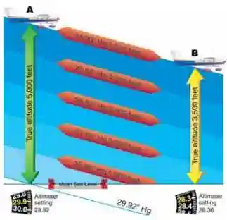
- Maintaining a current altimeter setting is critical because the atmosphere pressure is not constant
- That is, in one location the pressure might be higher than the pressure just a short distance away
- Take an aircraft whose altimeter setting is set to 29.92" of local pressure
- As the aircraft moves to an area of lower pressure (Point A to B in [Figure 10]) and the pilot fails to readjust the altimeter setting (essentially calibrating it to local pressure), then as the pressure decreases, the true altitude will be lower
- When the altimeter shows an indicated altitude of 5,000', the true altitude at Point A (the height above mean sea level) is only 3,500' at Point B
- The fact that the altitude indication is not always true lends itself to the memory aid, "When flying from hot to cold or from a high to a low, look out below"
-
High Barometric Pressure:
- Cold, dry air masses may produce barometric pressures in excess of 31.00 inches of Mercury
- Many altimeters do not have the means to adjust for settings of these levels
- In this case, the aircraft actual altitude will be higher than the altimeter indicates
-
Low Barometric Pressure:
- When abnormally low barometric pressure conditions occur (below 28.00), flight operations by aircraft unable to set the actual altimeter setting are not recommended
- This is different from high barometric pressure because the aircraft's true altitude is lower than the indicated altitude
- This situation may be exacerbated when operating in extremely cold temperatures, which may result in the aircraft's true altitude being significantly lower than the indicated altitude
- When abnormally low barometric pressure conditions occur (below 28.00), flight operations by aircraft unable to set the actual altimeter setting are not recommended
- For instances where atmospheric pressure is notably higher or lower, specific altimeter procedures must be followed
- It is important to set the current altimeter settings for the area of operation when flying at an enroute altitude that does not require a standard altimeter setting of 29.92 "Hg

Cold Temperature Altimeter Procedures
- A correctly calibrated pressure altimeter indicates true altitude above mean sea level (MSL) when operating within the International Standard Atmosphere (ISA) parameters of pressure and temperature
- Nonstandard pressure conditions are corrected by applying the correct local area altimeter setting
- Temperature errors from ISA result in true altitude being higher than indicated altitude whenever the temperature is warmer than ISA and true altitude being lower than indicated altitude whenever the temperature is colder than ISA
- True altitude variance under conditions of colder than ISA temperatures poses the risk of inadequate obstacle clearance
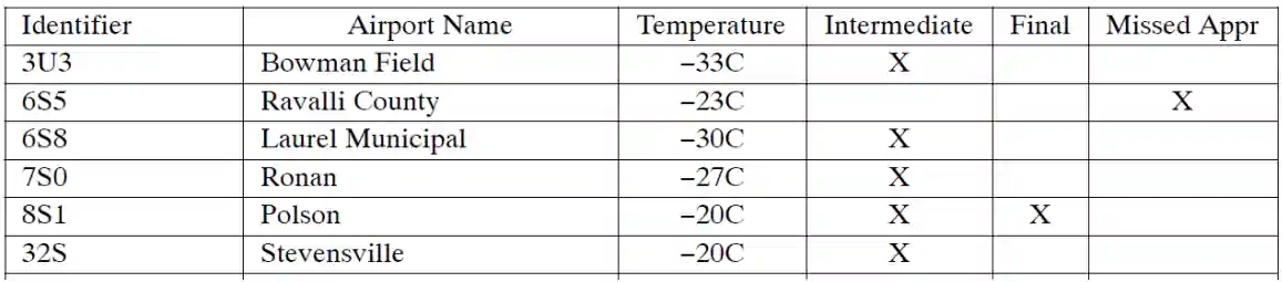
- Under extremely cold conditions, pilots may need to add an appropriate temperature correction determined from the chart in Figure 3-7 to charted IFR altitudes to ensure terrain and obstacle clearance with the following restrictions:
- Altitudes specifically assigned by Air Traffic Control (ATC), such as "maintain 5,000" shall not be corrected. Assigned altitudes may be rejected if the pilot decides that low temperatures pose a risk of inadequate terrain or obstacle clearance
- If temperature corrections are applied to charted IFR altitudes (such as procedure turn altitudes, final approach fix crossing altitudes, etc.), the pilot must advise ATC of the applied correction
- Flight planning into a CTA may be accomplished prior to flight
- Use the predicted coldest temperature for plus or minus 1 hour of the estimated time of arrival and compare against the CTA published temperature
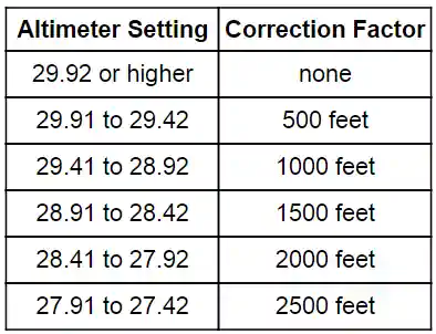
- If the predicted temperature is at or below CTA temperature, calculate an altitude correction using [Figure 4]
- This correction may be used at the CTA if the actual arrival temperature is the same as the temperature used to calculate the altitude correction during preflight planning
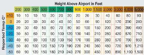
- TBL 7-3-1, derived from ICAO formulas, indicates how much error can exist when the temperature is extremely cold. To use the table, find the reported temperature in the left column, then read across the top row to locate the height above the airport/reporting station (i.e., subtract the airport/ reporting elevation from the intended flight altitude). The intersection of the column and row is how much lower the aircraft may actually be as a result of the possible cold temperature induced error
-
ICAO Cold Temperature Error Table
- The cold temperature induced altimeter error may be significant when considering obstacle clearances when temperatures are well below standard [Figure 4]
- Pilots may wish to increase their minimum terrain clearance altitudes with a corresponding increase in ceiling from the normal minimum when flying in the exetreme cold
- Most flight management systems (FMS) with air data computers implement a capability to compensate for cold temperature errors. Pilots flying with these systems should ensure they are aware of the conditions under which the system will automatically compensate
- If compensation is applied by the FMS or manually, ATC must be informed that the aircraft is not flying the assigned altitude
- Otherwise, vertical separation from other aircraft may be reduced, creating a potentially hazardous situation
- To use the table, find the reported temperature in the left column, and then read across the top row to the height above the airport/reporting station
- Subtract the airport elevation from the altitude of the intended flight altitude (final approach fix [FAF])
- The intersection of the column and row is the amount of possible error
- Example: The reported temperature is -10° Celsius and the FAF is 500' above the airport elevation
- The reported current altimeter setting may place the aircraft as much as 50' below the altitude indicated by the altimeter
- This number represents how far the aircraft may be below the indicated altitude due to possible cold temperature induced error
- Example: The reported temperature is -10° Celsius and the FAF is 500' above the airport elevation
- The reported current altimeter setting may place the aircraft as much as 50' below the altitude indicated by the altimeter
- Pilots are responsible to compensate for cold temperature altimetry errors when operating into an airport with any published cold temperature restriction and a reported airport temperature at or below the published temperature restriction
- Pilots must ensure compensating aircraft are correcting on the proper segment or segments of the approach
- Manually correct if compensating aircraft system is inoperable. Pilots manually correcting, are responsible to calculate and apply a cold temperature altitude correction derived from [Figure 4] to the affected approach segment or segments
- Pilots must advise the cold temperature altitude correction to Air Traffic Control (ATC). Pilots are not required to advise ATC of a cold temperature altitude correction inside of the final approach fix
- The possible result of the above example should be obvious, particularly if operating at the minimum altitude or when conducting an instrument approach. When operating in extreme cold temperatures, pilots may wish to compensate for the reduction in terrain clearance by adding a cold temperature correction
- EXAMPLE: Temperature-10 degrees Celsius, and the aircraft altitude is 1,000 feet above the airport elevation. The chart shows that the reported current altimeter setting may place the aircraft as much as 100 feet below the altitude indicated by the altimeter
- When using the cold temperature error table, the altitude error is proportional to both the height above the reporting station elevation and the temperature at the reporting station
- For IFR approach procedures, the reporting station elevation is assumed to be airport elevation
- It is important to understand that corrections are based upon the temperature at the reporting station, not the temperature observed at the aircraft's current altitude and height above the reporting station and not the charted IFR altitude
- To see how corrections are applied, note the following example:
- Airport Elevation: 496'
- Airport Temperature: - 50°C
- A charted IFR approach to the airport provides the following data:
- Minimum Procedure Turn Altitude: 1,800'
- Minimum FAF Crossing Altitude: 1,200'
- Straight-in Minimum Descent Altitude: 800'
- Circling MDA: 1,000'
- The Minimum Procedure Turn Altitude of 1,800' will be used as an example to demonstrate determination of the appropriate temperature correction
- Typically, altitude values are rounded up to the nearest 100' level
- The charted procedure turn altitude of 1,800' minus the airport elevation of 500' equals 1,300'
- The altitude difference of 1,300' falls between the correction chart elevations of 1,000' and 1,500'
- At the station temperature of -50°C, the correction falls between 300' and 450'
- Dividing the difference in compensation values by the difference in altitude above the airport gives the error value per foot
- In this case, 150' divided by 500' = 0.33' for each additional foot of altitude above 1,000'
- This provides a correction of 300' for the first 1,000' and an additional value of 0.33 times 300', or 99', which is rounded to 100'. 300' + 100' = total temperature correction of 400'
- For the given conditions, correcting the charted value of 1,800' above MSL (equal to a height above the reporting station of 1,300') requires the addition of 400'
- Thus, when flying at an indicated altitude of 2,200', the aircraft is actually flying a true altitude of 1,800'
- Minimum Procedure Turn Altitude 1,800' charted = 2,200' corrected
- Minimum FAF Crossing Altitude 1,200' charted = 1,500' corrected
- Straight-in MDA 800' charted = 900' corrected
- Circling MDA 1,000' charted = 1,200' corrected
- The cold temperature induced altimeter error may be significant when considering obstacle clearances when temperatures are well below standard [Figure 4]


Abnormal Atmopsheric Pressure Altimeter Procedures
- The aircraft cruising altitude or flight level is maintained by referencing the barometric altimeter
- Procedures for setting altimeters during high and low barometric pressure events must be set using the following procedures:
Below 18,000' MSL
-
Barometric pressure is 31.00 in-Hg or less:
- Set the altimeter to a current reported altimeter setting from a station along the route and within 100 NM of the aircraft, or;
- If there is no station within this area, use the current reported altimeter setting of an appropriate available station, or;
- If the aircraft is not equipped with a radio, set the altimeter to the elevation of the departure airport or use an available appropriate altimeter setting prior to departure
-
Barometric pressure exceeds 31.00 in-Hg:
- The following procedures will be placed in effect by NOTAM defining the geographic area affected:
- For all aircraft: Set 31.00 inches for en route operations below 18,000 feet MSL
- Maintain this setting until beyond the affected area or until reaching final approach segment on an instrument approach
- At the beginning of the final approach segment, the current altimeter setting will be set, if possible
- If no current altimeter setting is available, or if a setting above 31.00" Hg. cannot be made on the aircraft's altimeter, leave 31.00" Hg. set in the altimeter and continue the approach
- Set 31.00 "Hg. in the altimeter prior to reaching the lowest of any mandatory/crossing altitudes or 1,500 feet above ground level (AGL) when on a departure or missed approach
- Air traffic control will issue actual altimeter settings and advise pilots to set 31.00 inches in their altimeters for en route operations below 18,000 feet MSL in affected areas
- For aircraft with the capability of setting the current altimeter setting and operating into airports with the capability of measuring the current altimeter setting, no additional restrictions apply
- Flight operations are restricted to VMC to and from an airport that is unable to accurately measure barometric pressures above 31.00" Hg
- These airports will report the barometric pressure as "missing" or "in excess of 31.00" Hg"
- For aircraft operating VFR, there are no additional restrictions, however, extra diligence in flight planning and in operating in these conditions is essential
- For aircraft operating IFR and unable to set the current altimeter setting, the following restrictions apply:
- The suitability of departure alternate airports, destination airports, and destination alternate airports will be determined by increasing the published ceiling and visibility requirements when unable to set the aircraft altimeter above 31.00" Hg. Any reported or forecast altimeter setting over 31.00" Hg. will be rounded up to the next tenth to calculate the required increases. The ceiling will be increased by 100 feet and the visibility by 1/4 statute mile for each 1/10" Hg. over 31.00" Hg. Use these adjusted values in accordance with operating regulations and operations specifications
- Example: Destination airport altimeter is 31.21 "Hg. The planned approach is an instrument landing system (ILS) with a decision altitude (DA) 200 feet and visibility 1/2 mile (200-1/2). Subtract 31.00 "Hg. from 31.21 "Hg. to get .21 "Hg. .21 "Hg rounds up to .30 "Hg. Calculate the increased requirement: 100 feet per 1/10 equates to a 300 feet increase for .30 "Hg. 1/4 statute mile per 1/10 equates to a 3/4 statute mile increase for .30 "Hg. The destination weather requirement is determined by adding the 300-3/4 increase to 200-1/2. The destination weather requirement is now 500-1 1/4
- On approach, 31.00" Hg. will remain set during the complete instrument approach
- The aircraft has arrived at the DA or minimum descent altitude (MDA) when the published DA or MDA is displayed on the barometric altimeter
- Although visibility is normally the limiting factor on an approach, pilots should be aware that when reaching DH the aircraft will be higher than indicated
- Using the example above the aircraft would be approximately 300 feet higher
- These restrictions do not apply to authorized Category II/III ILS operations and certificate holders using approved atmospheric pressure at aerodrome elevation (QFE) altimetry systems
- The following procedures will be placed in effect by NOTAM defining the geographic area affected:
-
-
At or above 18,000' MSL:
- Pilots set the altimeter to the standard 29.92 when entering the "flight levels"
- Since VFR pilots can fly at 17,500' MSL, atmospheric pressures below 29.92 inHg (think "when flying high to low, lookout below") will bring those pilots flying at 18,000' MSL lower, decreasing the required 500' separation from possible VFR traffic
- As a result, ATC establishes a lowest usable flight level depending upon the atmospheric pressure in an area of operation
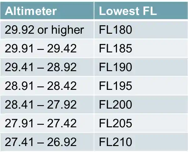
- The lowest usable flight level is determined by the atmospheric pressure in the area of operation as shown in [Figure 12]
- When the minimum altitude per 14 CFR Section 91.159 and 14 CFR Section 91.177 is above 18,000 feet MSL, the lowest usable flight level must be the flight level equivalent of the minimum altitude plus the number of feet specified in [Figure 13]
- ATC will accomplish this calculation
- EXAMPLE: The minimum safe altitude of a route is 19,000' MSL and the altimeter setting is reported between 29.92 and 29.42 inches of mercury, the lowest usable flight level will be 195, which is the flight level equivalent of 19,500 feet MSL (minimum altitude plus 500 feet)
- ATC will accomplish this calculation

Altimeter Enhancements (Encoding)
- It is not sufficient in the airspace system for only the pilot to have an indication of the aircraft's altitude; the air traffic controller on the ground must also know the altitude of the aircraft
- To provide this information, the aircraft is typically equipped with an encoding altimeter
- When the ATC transponder is set to Mode C, the encoding altimeter supplies the transponder with a series of pulses identifying the flight level (in increments of 100') at which the aircraft is flying
- This series of pulses is transmitted to the ground radar where they appear on the controller's scope as an alphanumeric display around the return for the aircraft
- The transponder allows the ground controller to identify the aircraft and determine the pressure altitude at which it is flying
- A computer inside the encoding altimeter measures the pressure referenced from 29.92" Hg and delivers this data to the transponder
- When the pilot adjusts the barometric scale to the local altimeter setting, the data sent to the transponder is not affected
- This is to ensure that all Mode C aircraft are transmitting data referenced to a common pressure level
- ATC equipment adjusts the displayed altitudes to compensate for local pressure differences allowing display of targets at correct altitudes
- 14 CFR part 91 requires the altitude transmitted by the transponder to be within 125' of the altitude indicated on the instrument used to maintain flight altitude
Altimeter Preflight Action
- Should indicate within 75' of field elevation when set with the proper barometric pressure (not regulatory) according to Aeronautical Information Manual 7-2-3
- Operating with a known altimeter error, especially in IFR conditions, may not be illegal but certainly falls under careless and reckless operation
- If you set your altimeter according to ATIS/AWOS and it is not perfect for field elevation, remember your location on the field
- Filed elevation: the highest elevation of any usable landing surface
- Gliders may set the airport elevation so they can know AGL
- Obtaining an altimeter setting:
- Altimeter settings can be obtained from ATC, automated broadcasts, weather reports, as well as various other applications and programs
Inertial Reference Unit (IRU), Inertial Navigation System (INS), and Attitude Heading Reference System (AHRS)
- IRUs are self-contained systems comprised of gyros and accelerometers that provide aircraft attitude (pitch, roll, and heading), position, and velocity information in response to signals resulting from inertial effects on system components
- Once aligned with a known position, IRUs continuously calculate position and velocity. IRU position accuracy decays with time
- This degradation is known as "drift"
- INSs combine the components of an IRU with an internal navigation computer
- By programming a series of waypoints, these systems will navigate along a predetermined track
- AHRSs are electronic devices that provide attitude information to aircraft systems such as weather radar and autopilot, but do not directly compute position information.
- Aircraft equipped with slaved compass systems may be susceptible to heading errors caused by exposure to magnetic field disturbances (flux fields) found in materials that are commonly located on the surface or buried under taxiways and ramps
- These materials generate a magnetic flux field that can be sensed by the aircraft's compass system flux detector or "gate", which can cause the aircraft's system to align with the material's magnetic field rather than the earth's natural magnetic field.
- The system's erroneous heading may not self-correct.
- Prior to take off pilots should be aware that a heading misalignment may have occurred during taxi.
- Pilots are encouraged to follow the manufacturer's or other appropriate procedures to correct possible heading misalignment before take off is commenced.
Altimeter Anomalies and Malfunctions
- Pitot-Static system errors are generally the highest at low airspeed (high angles of attack)
-
Static System Blockage:
- Trapped static pressure causes the altimeter to freeze at the altitude where the blockage occurred
- Revert to alternate static source and pilot operating handbook procedures
- If no alternate static source is available and the situation calls for it, consider breaking the VSI glass to introduce cabin static air
- Consider approaches that offer glideslope guidance that is not dependent upon altitude (i.e., an ILS)
- While alternate static pressure will likely place the aircraft higher than shown on the instruments, that is not a guarantee
- Avoid flying any instrument approaches, especially to minimums
Altimeter Knowledge Quiz
Conclusion
- EXTREME CAUTION SHOULD BE EXERCISED WHEN FLYING IN PROXIMITY TO OBSTRUCTIONS OR TERRAIN IN LOW TEMPERATURES AND/OR PRESSURES
- This is especially true in extremely cold temperatures that cause a large differential between the Standard Day temperature and actual temperature. This circumstance can cause serious errors that result in the aircraft being significantly lower than the indicated altitude
- Standard temperature at sea level is 15° Celsius (59° Fahrenheit). The temperature gradient from sea level is minus 2° Celsius (3.6° Fahrenheit) per 1,000'. Pilots should apply corrections for static pressure systems and/or instruments, if appreciable errors exist
- This is especially true in extremely cold temperatures that cause a large differential between the Standard Day temperature and actual temperature. This circumstance can cause serious errors that result in the aircraft being significantly lower than the indicated altitude
- Unless under control of ATC, altitudes are not assigned to pilot's, however, to ensure safety and instrumentation accuracy, local altimeter settings are still very important
- Instances where VFR pilots need to be accurate with their altitude include flying VFR cruising altitudes, flying traffic patterns, and maintaining minimum heights above protected areas
- Keep up with the local altimeter setting and be sure to adjust it regularly
- Altimeter settings are especially important during Instrument Flight Rules where separation responsibilities fall upon ATC, and in areas of mountainous terrain or obstacles where clearance margins are thinner
- Realize different terminologies surround altimeter readings (just as altitude as AGl, MSL, etc.) which include:
- QNE: En-route (MSL)
- QFE: Height above field elevation (AGL)
- QNH: Local altimeter setting
- A NOTAM will be issued defining the geographic area affected
- The adoption of a standard altimeter setting at the higher altitudes eliminates station barometer errors, some altimeter instrument errors, and errors caused by altimeter settings derived from different geographical sources
- The FAA Regional Flight Standards Division Manager of the affected area is authorized to approve temporary waivers to permit emergency resupply or emergency medical service operation
- Always keep in mind the effects of parallax error
- Pilots should apply corrections for static pressure systems and/or instruments, if appreciable errors exist
- Changing altimeter settings is critical during frontal passes
- Air traffic controllers will furnish altimeter information at least once when en route or on an instrument flight plan within their controlled airspace
- Still looking for something? Continue searching:
Aircraft Altimeter References
- Aeronautical Information Manual (1-1-15) Inertial Reference Unit (IRU), Inertial Navigation System (INS), and Attitude Heading Reference System (AHRS)
- Aeronautical Information Manual (7-2-1) General
- Aeronautical Information Manual (7-2-2) Barometric Pressure Altimeter Errors
- Aeronautical Information Manual (7-2-3) Altimeter Errors
- Federal Aviation Administration - Pilot/Controller Glossary
- Federal Aviation Regulations (91.119) Minimum safe altitudes: General
- Federal Aviation Regulations (91.121) Altimeter settings
- Federal Aviation Regulations (91.177) Minimum altitudes for IFR operations
- Federal Aviation Regulations (91.411) Altimeter system and altitude reporting equipment tests and inspections
- Instrument Flying Handbook (3-3) Sensitive Altimeter
- AOPA - Density Altitude Quiz
- Instrument Flying Handbook (3-3) Sensitive Altimeter
- Instrument Flying Handbook (3-3) Sensitive Altimeter
- Pilot Workshops - IFR Challenge: Lowball in High Country
- CFI Notebook.net - Pitot Static System
- Instrument Flying Handbook (3-3) Sensitive Altimeter