Navigation Charts
Civil aeronautical charts for the U.S. and its territories and possessions are produced by the Federal Aviation Administration to aid pilots in navigation.
VFR Navigation Charts
- VFR Navigation charts consist of the following:
-
Sectional Aeronautical Chart:
- Designed for visual navigation of slow to medium speed aircraft [/]
- The topographic information consists of contour lines, shaded relief, drainage patterns, and an extensive selection of visual checkpoints and landmarks used for flight under VFR.
- Cultural features include cities and towns, roads, railroads, and other distinct landmarks.
- The aeronautical information includes visual and radio aids to navigation, airports, controlled airspace, special-use airspace, obstructions, and related data.
- Historically, VFR chart legends described private airports as charted for "emergency or landmark value." Effective November 3, 2022, the FAA removed references to emergency use; beyond December 29, 2022, private airports continue to be charted for their landmark value using the FAA's established evaluation criteria.
- Not every private-use airport is necessarily depicted, so the omission of a private airport from a sectional chart does not by itself establish that the airport no longer exists; verify current airport information using appropriate aeronautical data and publications.
- FAA VFR charts intentionally provide only limited, skeletonized aeronautical data outside the U.S. Flight Information Region; use the appropriate foreign charts and flight information publications for navigation outside U.S. airspace.
- Scale 1 inch = 6.86nm/1:500,000
- Revised every 56 days, except most Alaskan charts are revised annually.
- Charts can be purchased through Amazon.
-
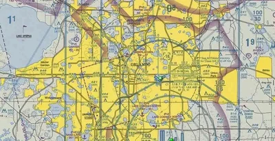
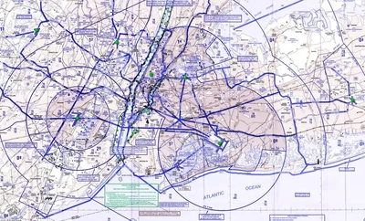
Terminal Area Chart (TAC):
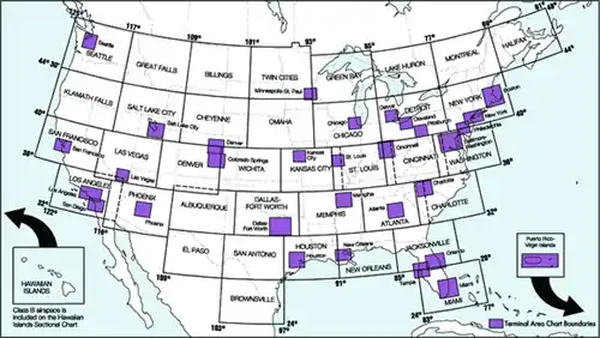
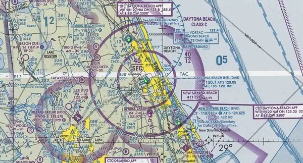
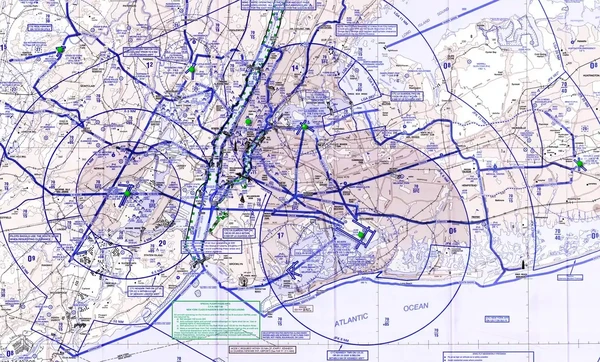
- TACs depict the airspace designated as Class B airspace. []
- While similar to sectional charts, TACs have more detail because the scale is larger.
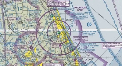
- Should be used by pilots intending to operate to or from airfields within or near Class B or class C airspace.
- Charted VFR Flyway Planning Charts are published on the back of the existing VFR Terminal Area Charts.
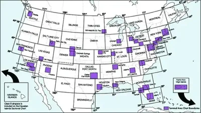
- Areas with TAC coverage are indication by a dot on the Sectional Chart indexes.
- Scale 1 inch = 3.43nm/1:250,000
- Charts are revised every 56 days, except Puerto Rico-Virgin Islands revised annually.
- Charts can be purchased through Amazon.
-
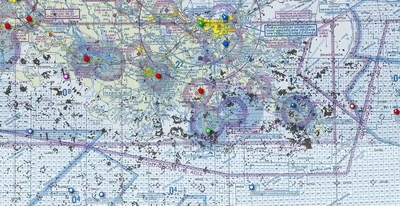
U.S. Gulf Coast VFR Aeronautical Chart:
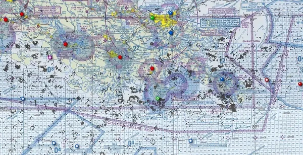
- Designated primarily for helicopter operation in the Gulf of Mexico area. []
- Information depicted includes offshore mineral leasing areas and blocks, oil drilling platforms, and high density helicopter activity areas.
- Scale 1 inch = 13.7/1:1,000,000
- Revised every 56 days.
- Charts can be purchased through Amazon.
-
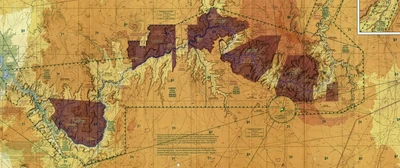
Grand Canyon VFR Aeronautical Chart:
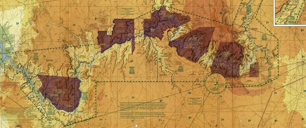
- Covers the Grand Canyon National Park area and is designated to promote aviation safety, flight free zones, and facility VFR navigation in this popular area. []
- The chart contains aeronautical information for general aviation for VFR pilots on one side and commercial VFR air tour operators on the other side.
- Revised every 56 days.
- Learn more here.
- Charts can be purchased through Amazon.
-
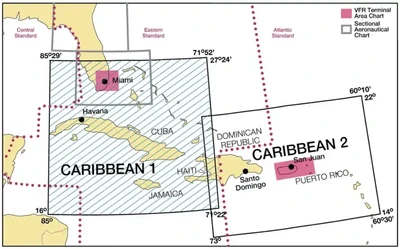
Caribbean VFR Aeronautical Charts:
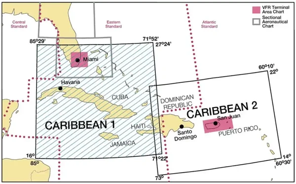
- Caribbean 1 and 2 (CAC-1 and CAC-2) are designed for visual navigation to assist familiarization of foreign aeronautical and topographic information. []
- The aeronautical information includes visual and radio aids to navigation, airports, controlled airspace, special-use airspace, obstructions, and related data.
- The topographic information consists of contour lines, shaded relief, drainage patterns, and a selection of landmarks used for flight under VFR.
- Cultural features include cities and towns, roads, railroads, and other distinct landmarks.
- Scale 1 inch = 13.7nm/1:1,000,000
- CAC-1, revised annually.
- CAC-2, revised biennially.
-
Helicopter Route Chart:
- A three-color chart series which shows current aeronautical information useful to helicopter pilots navigating in areas with high concentrations of helicopter activity. []
- Information depiction includes helicopter routes, four classes of heliports with associated frequency and lighting capabilities, NAVAIDs, and obstructions.
- In addition, pictorial symbols, roads, and easily identified geographical features are portrayed.
- Have a longer life span than other charts and may be current for several years, updated as requested.
- Printed on a durable plastic material
- Scale 1 inch = 1.71nm/1:125,000
- Revised every 56 days.
- Charts can be purchased through Amazon.

IFR Navigation Charts
-
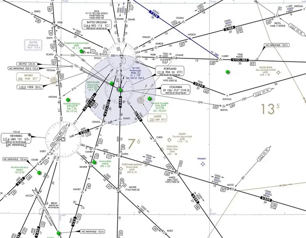
En-route Low Altitude Chart (Conterminous U.S. and Alaska):
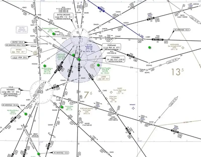
- Provide aeronautical information navigation under IFR conditions below 18,000' MSL. []
- This four-color chart series includes airways; limits of controlled airspace; VHF NAVAIDs with frequency, identification, channel, geographic coordinates; airports with terminal air/ground communication; minimum en route and obstruction clearance altitudes; airway distances; reporting points; special use airspace; and military training routes.
- Scales vary from 1 inch = 5nm to 1 inch = 20nm
- Charts revised every 56 days.
- Area charts show congested terminal areas at large scale.
- They are included with subscriptions to any conterminous U.S. Set Low (full set, East or West sets).
- U.S. IFR Enroute Charts emphasize the transition point beyond U.S. controlled airspace where aviators will then consult charting products of other nations or third-party providers.
- The FAA does not reliably receive foreign data with sufficient lead times to produce the foreign areas of FAA charts with the same robust, for navigation, content as within U.S. airspace.
- Additionally, foreign aeronautical information is not supported by the U.S. NOTAM System.
-
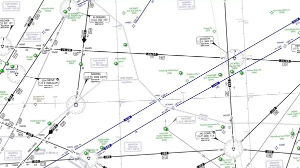
En-route High Altitude Charts (Conterminous U.S. and Alaska):
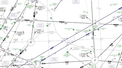
- Designated for navigation at or above 18,000' MSL (up to FL 600). []
- This four-color chart series includes the jet route structure; VHF NAVAIDs with frequency, identification, channel, geographic coordinates; selected airports; reporting points.
- Scales vary from 1 inch to 45nm to 1 inch = 18nm
- Revised every 56 days.
-
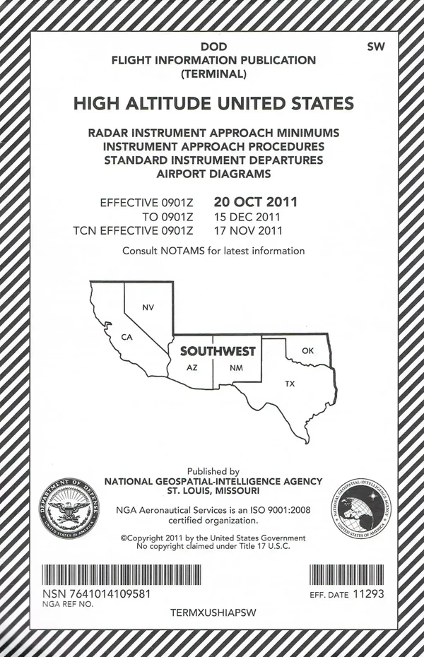
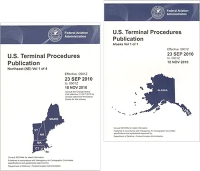
U.S. Terminal Procedures Publication (TPP):
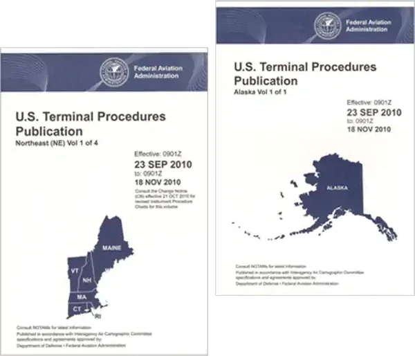
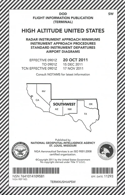
- TPPs are published in 24 loose-leaf or perfect bound volumes covering the conterminous U.S., Puerto Rico and the Virgin Islands [/]
- A Change Notice is published at the midpoint between revisions in bound volume format and is available on the internet for a free download at the AeroNav website.
- Civil airport charts are organized alphabetically by the associated city and then by airport name. Military airport charts are organized alphabetically by airport name and then by the associated city.
-
Instrument Approach Procedure (IAP) Charts:
- IAP charts portray the aeronautical data that is required to execute instrument approaches to airports.
- Each chart depicts the IAP, all related navigation data, communications information, and an airport sketch.
- Each procedure is designated for use with a specific electronic navigational aid, such as ILS, VOR, NDB, RNAV, etc.
-
Instrument Departure Procedure (DP) Charts:
- Designated to expedite clearance delivery and to facilitate transition between takeoff and en route operations.
- Furnishes pilots departure routing clearance information in graphic and textual form.
- Current charted DPs are available as individual charts through the FAA's digital Terminal Procedures Publication search.
-
Standard Terminal Arrival (STAR) Charts:
- Designated to expedite ATC arrival procedures and to facilitate transition between en route and instrument approach operations.
- They depict pre-planned IFR ATC arrival procedures in graphic and textual form.
- Each STAR procedure is presented as a separate chart and may serve either a single airport or more than one airport in a given geographical area.
- Current STAR charts are available as individual charts through the FAA's digital Terminal Procedures Publication search.
- Use the TPP index or digital search rather than assuming a DP or STAR appears immediately before a particular airport's instrument approach charts.
-
Airport Diagrams:
- Full page airport diagrams are designed to assist in the movement of ground traffic at locations with complex runway/taxiway configurations and provided information for updating geodetic position navigational systems aboard aircraft.
- Airport diagrams are available for free download at the AeroNav website here.
-
Alaska Terminal Procedures Publications:
- Contains all terminal flight procedures for civil and military aviation in Alaska.
- Included are IAP charts, DP charts, STAR charts, airport diagrams, radar minimums, and supplementary support data such as IFR alternate minimums, take-off minimums, rate of descent tables, rate of climb tables and inoperative components tables.
- Volume is 5-3/8 x 8-1/4 inch top bound
- Revised every 56 days with provisions for a Terminal Change Notice, as required.
- Charts can be purchased through Amazon.
Planning Charts
-
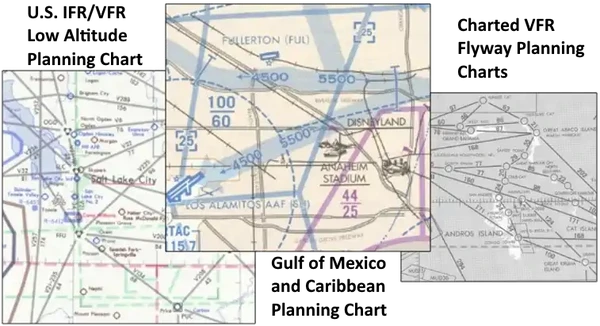
Planning charts consist of the following: []:
-
U.S. IFR/VFR Low Altitude Planning Chart:
- Designated for preflight and en route flight planning for IFR/VFR flights.
- Depiction includes low altitude airways and mileage, NAVAIDs, airports, special use airspace, cities, time zones, major drainage, and directory of airports with their airspace classification, and a mileage table showing great circle distances between major airports.
- Scale 1 inch = 47nm/1:3,400,000
- Revised annually, and is available either folded or unfolded for wall mounting.
-
Gulf of Mexico and Caribbean Planning Chart:
- A VFR planning chart on the reverse side of the Puerto Rico-Virgin Islands VFR Terminal Area Chart.
- Includes mileage between airports of entry, a selection of special use airspace and a directory of airports with their available services.
- Scale 1 inch = 85nm/1:6,192,178
- 60x20 inches folded to 5x10 inches.
- Revised annually.
-
Alaska VFR Wall Planning Chart:
- This chart is designed for VFR preflight planning and chart selection.
- It includes aeronautical and topographic information of the state of Alaska.
- The aeronautical information includes public and military airports; radio aids to navigation; and Class B, Class C, TRSA and special-use airspace.
- The topographic information includes city tint, populated places, principal roads, and shaded relief.
- Scale 1 inch = 27.4nm/1:2,000,000
- The one sided chart is 58.5 x 40.75 inches and is designed for wall mounting.
- Chart is revised biennially
-
U.S. VFR Wall Planning Chart:
- This chart is designed for VFR preflight planning and chart selection.
- It includes aeronautical and topographic information of the conterminous U.S.
- The aeronautical information includes airports, radio aids to navigation, Class B airspace and special use airspace.
- The topographic information includes city tint, populated places, principal roads, drainage patterns, and shaded relief.
- Scale 1 inch = 43 nm/ 1:3,100,000
- The one-sided chart is 59 x 36 inches and ships unfolded for wall mounting.
- Chart is revised biennially
-
Charted VFR Flyway Planning Charts:
- Printed on the reverse side of selected TAC charts.
- The coverage is the same as the associated TAC.
- Flyway planning charts depict flight paths and altitudes recommended for use to bypass high traffic areas.
- Ground references are provided as a guide for visual orientation.
- Flyway planning charts are designed for use in conjunction with TACs and sectional charts and not to be used for navigation.
- Chart scale 1 inch = 3.43/1:250,000
Supplementary Charts and Publications
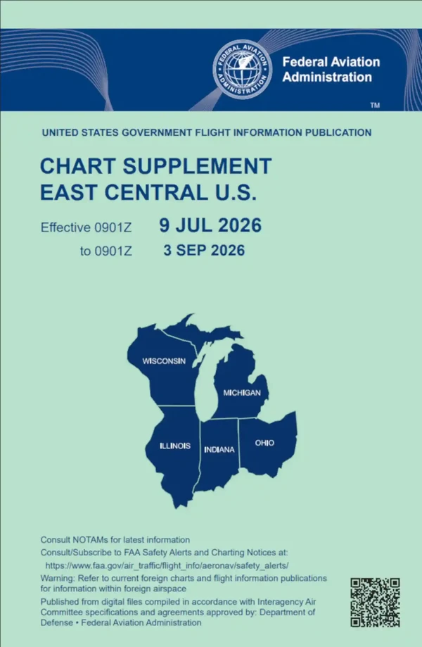
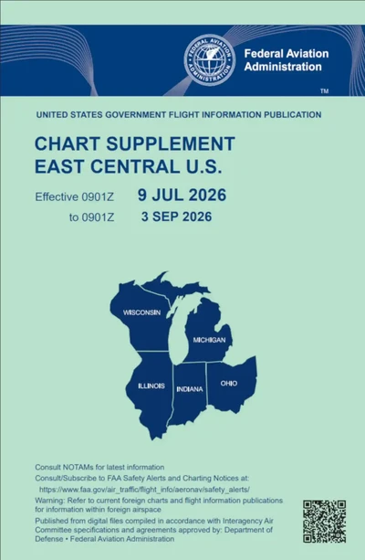
- Chart Supplement refers to a series of civil/military flight information publications consisting of:
-
Chart Supplement U.S.:
- 7-Volume booklet series is designed for use with appropriate IFR or VFR charts and contains data including, but not limited to, airports, NAVAIDs, communications data, weather data sources, special notices, non−regulatory operational procedures, and airport diagrams.
- Coverage includes the conterminous U.S., Puerto Rico, and the Virgin Islands.
- The Chart Supplement U.S. shows data that cannot be readily depicted in graphic form; for example, airport hours of operations, types of fuel available, runway widths, lighting codes.
- Also provides a means for pilots to update visual charts between edition dates
- Published every 56 days while sectional and Terminal Area charts are generally revised every 6 months.
- Volumes are side-bound 5-3/8 x 8-1/4 inches
- Found here.
-
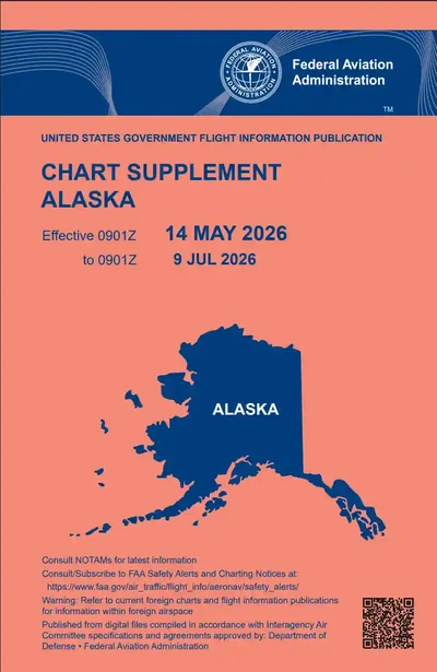
Supplement Alaska:
- This single−volume book is designed for use with appropriate IFR or VFR charts. []
- The Chart Supplement Alaska contains data including, but not limited to, airports, NAVAIDs, communications data, weather data sources, special notices, non−regulatory operational procedures, and airport diagrams.
- The publication also includes uniquely geographical operational requirements as area notices and emergency procedures.
- Volume is side-bound 5-3/8 x 8-1/4 inches
- Found here.
-
Chart Supplement Pacific:
- This single volume book is designed for use with appropriate IFR or VFR charts. []
- The Chart Supplement Pacific contains data including, but not limited to, airports, NAVAIDs, communications data, weather data sources, special notices, non−regulatory operational procedures, and airport diagrams.
- The publication also includes airspace, navigational facilities, non−regulatory Pacific area procedures, Instrument Approach Procedures (IAP), Departure Procedures (DP), Standard Terminal Arrival (STAR) charts, radar minimums, supporting data for the Hawaiian and Pacific Islands, and uniquely geographical operational requirements as area notices and emergency procedures.
- Volume is side-bound 5-3/8 x 8-1/4 inches
-
North Atlantic Route Chart:
- Designed for FAA controllers to monitor transatlantic flights, this 5−color chart shows oceanic control areas, coastal navigation aids, oceanic reporting points, and NAVAID geographic coordinates. Full Size Chart: Scale 1 inch = 113.1 nm/1:8,250,000.
Full Size Chart:
- Scale 1 inch = 113.1nm/1:8,250,000
- Chart is shipped flat only
Half Size Chart:
- Scale 1 inch = 150.8/1:11,000,000
- Chart is 29-3/4 x 20-1/2 inches
- Shipped folded to 5x10 inches only.
- Chart revised every 56 days
-
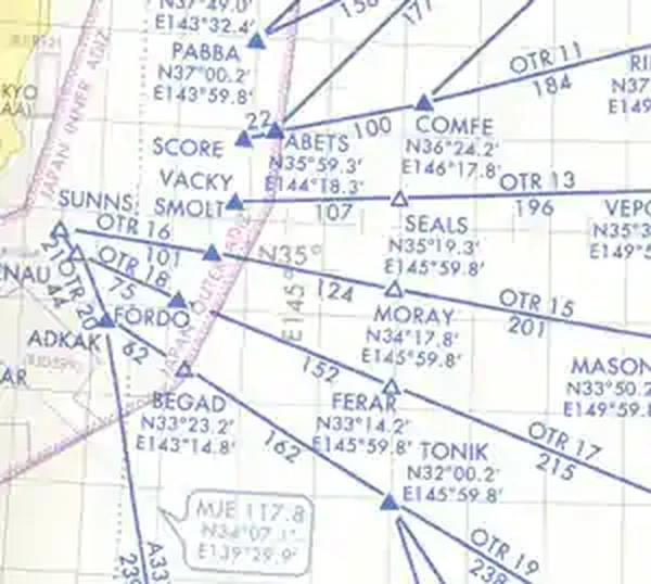
North Pacific Route Charts:
- Designed for FAA controllers to monitor transoceanic flights. []
- The show established intercontinental air routes, including reporting points with geographic positions.
Composite Chart:
- Scale 1 inch = 164nm/1:12,000,000
- 48 x 41 1/2 inches
- Charts are revised every 56 days.
Area Charts:
- Scale 1 inch = 95.9nm/1:7,000,000
- 52 x 40 1/2 inches
- Revised every 56 days.
-
Airport Obstruction Charts (OC):
- The OC is a 1:12,000 scale graphic depicting part 77, Objects Affecting Navigable Airspace surfaces, a representation of objects that penetrate these surfaces, aircraft movement and apron areas, navigational aids, prominent airport buildings, and a selection of roads and other planimetric detail in the airport vicinity.
- Also included are tabulations of runway and other operational data.
-
FAA Aeronautical Chart User's Guide:
- A booklet designed to be used as a teaching aid and reference document.
- It describes the substantial amount of information provided on FAA's aeronautical chart and publications.
- It includes explanations and illustrations of chart terms and symbols organized by chart type.
- The users guide is available for free download at the AeroNav website.



Digital Products
- The Digital Aeronautical Information CD (DAICD).
- The NAVAID Digital Data File.
- The Digital Obstacle File.
- The Coded Instrument Flight Procedures.
-
The Digital Aeronautical Information CD (DAICD):
- The DAICD is a combination of the NAVAID Digital Data File, the Digital Chart Supplement, and the Digital Obstacle File on one Compact Disk.
- These three digital products are no longer sold separately.
- The files are updated every 56 days and are available by subscription only.
-
The NAVAID Digital Data File:
- This file contains a current listing of NAVAIDs that are compatible with the National Airspace System.
- This file contains all NAVAIDs including ILS and its components, in the U.S., Puerto Rico, and the Virgin Islands plus bordering facilities in Canada, Mexico, and the Atlantic and Pacific areas.
-
The Digital Obstacle File:
- This file describes all obstacles of interest to aviation users in the U.S., with limited coverage of the Pacific, Caribbean, Canada, and Mexico.
- The obstacles are assigned unique numerical identifiers, accuracy codes, and listed in order of ascending latitude within each state or area.
-
The Coded Instrument Flight Procedures (CIFP) (ARINC 424 [Ver 13 & 15]):
- The CIFP is a basic digital dataset, modeled to an international standard, which can be used as a basis to support GPS navigation. Initial data elements included are: Airport and Helicopter Records, VHF and NDB Navigation aids, en route waypoints and airways. Additional data elements will be added in subsequent releases to include: departure procedures, standard terminal procedures. The database is updated every 28 days. The data is available by subscription only and is distributed on CD-ROM or by ftp download arrivals, and GPS/RNAV instrument approach.
-
Digital-Visual Charts (d-VC):
- These digital VFR charts are geo-referenced images of FAA Sectional Aeronautical, TAC, and Helicopter Route charts. Additional digital data may easily be overlaid on the raster image using commonly available Geographic Information System software. Data such as weather, temporary flight restrictions, obstacles, or other geospatial data can be combined with d-VC data to support a variety of needs. The file resolution is 300 dots per inch and the data is 8-bit color. The data is provided as a GeoTIFF and distributed on DVD-R media and on the AeroNav Products website. The root mean square error of the transformation will not exceed two pixels. Digital-VC DVDs are updated every 28 days and are available by subscription only.
Foreign Area Publications
- National Geospatial-Intelligence Agency (NGA) Products:
- Canadian Charts.
- Mexican Charts.
- International Civil Aviation Organization (ICAO).
-
National Geospatial-Intelligence Agency (NGA) Products:
- For the latest information regarding publication availability visit the NGA website.
-
Flight Information Publication (FLIP) Planning Documents:
- General Planning (GP).
- Area Planning.
- Area Planning - Special Use Airspace - Planning Charts.
-
FLIP En-route Charts and Chart Supplements:
- Pacific, Australasia, and Antarctica.
- U.S. - IFR and VFR Supplements.
- Flight Information Handbook.
- Caribbean and South America - Low Altitude.
- Caribbean and South America - High Altitude.
- Europe, North Africa, and Middle East - Low Altitude.
- Europe, North Africa, and Middle East - High Altitude.
- Africa
- Eastern Europe and Asia.
- Area Arrival Charts.
-
FLIP Instrument Approach Procedures (IAPs):
- Africa
- Canada and North Atlantic.
- Caribbean and South America.
- Eastern Europe and Asia.
- Europe, North Africa, and Middle East.
- Pacific, Australasia, and Antarctica.
- VFR Arrival/Departure Routes - Europe and Korea.
- U.S.
-
Miscellaneous DOD Charts and Products:
- Aeronautical Chart Updating Manual (CHUM).
- DOD Weather Plotting Charts (WPC).
- Tactical Pilotage Charts (TPC).
- Operational Navigation Charts (ONC).
- Global Navigation and Planning Charts (GNC).
- Jet Navigation Charts (JNC) and Universal Jet Navigation Charts (JNU).
- Jet Navigation Charts (JNCA).
- Aerospace Planning Charts (ASC).
- Oceanic Planning Charts (OPC).
- Joint Operations Graphics - Air (JOG-A).
- Standard Index Charts (SIC).
- Universal Plotting Sheet (VP-OS).
- Sight Reduction Tables for Air Navigation (PUB249).
- Plotting Sheets (VP-30).
- Dial-Up Electronic CHUM.
-
- For the latest information regarding publication availability visit the NGA website.
-
Canadian Charts:
- Information on available Canadian charts and publications may be obtained from designated FAA chart agents or by contacting the:
Aeronautical Publications.
Sales and Distribution Unit.
P.O. Box 9840, Station T.
Ottawa, Ontario K1G 6S8 Canada.
Telephone: 613-744-6393 or 1-866-731-7827.
Fax: 613-744-7120 or 1-866-740-9992.
-
Mexican Charts:
- Information on available Mexican charts and publications may be obtained by contacting:
Blvd. Puerto Aereo 485.
Zona Federal Del Aeropuerto Int'l.
15620 Mexico D.F.
Mexico
-
International Civil Aviation Organization (ICAO):
- A list of free ICAO publications and catalogs is available at the following website: https://www.icao.int/publications/Pages/default.aspx.
Chart Symbology
- Chart information is available on the navigation chart being used or the Aeronautical Chart Users' Guide.
Sectional and Terminal Area Chart Symbol Reference
Use this study reference with the current chart legend. Chart symbols are condensed representations; always verify the current chart edition, notes, tabulations, and applicable operating rules.
VFR Airports
| Chart cue | Meaning and use |
|---|---|
| On an FAA Sectional, what does a blue civil-airport symbol indicate compared with a magenta one | Blue indicates an airport with a control tower; magenta indicates an airport without a control tower. The color distinguishes tower status, not public/private ownership or instrument-approach availability. |
| When is a recognizable runway pattern normally drawn inside a public-use airport symbol on an FAA Sectional | When the airport has at least one hard-surfaced runway 1,500 feet or longer. Shorter hard-surfaced runways and soft-surface airports use other airport symbols even though the landing area may be usable. |
| What does the combined civil-military airport symbol identify on an FAA Sectional | An airport used jointly for civil and military operations. It is distinct from a military-only airport and from a civilian airport merely located near military airspace. |
| What does the military-airport symbol identify on an FAA Sectional | A military airport; refueling and repair facilities are not indicated by the symbol. The chart symbol identifies the airport type but does not promise transient services. |
| What does the selected heliport symbol identify on an FAA Sectional | A selected heliport, with blue or magenta color indicating towered or nontowered status. The symbol does not by itself establish public use, fuel availability, or a fixed-wing runway. |
| What does the ultralight-flight-park symbol identify on an FAA Sectional | A selected ultralight flight park. The symbol warns pilots of a location where ultralight activity may be expected. |
| What does a small open-circle landmark-value landplane symbol indicate on an FAA Sectional | A landing area shown for landmark value where fuel is unavailable or complete information is unavailable. It is not the same as a normal public-use airport with a depicted runway pattern. |
| What does the public-use airport symbol for a soft-surfaced runway or hard-surfaced runway shorter than 1,500 feet indicate | A public-use airport in that runway category, with fuel not available as indicated by the legend. Public use does not imply that fuel or a long paved runway is available. |
| What does the restricted-or-private airport symbol for a soft-surfaced runway or hard-surfaced runway shorter than 1,500 feet indicate | A non-public-use landing area shown because it has landmark value. The chart depiction is not permission to land; prior authorization may be required. |
| What does the word CLOSED associated with a hard-surfaced airport symbol mean | The airport is closed; it may remain charted for visual identification or landmark value. A charted runway outline does not make a closed airport available for routine use. |
| What does OBJECTIONABLE next to an airport on an FAA Sectional mean | The airport received an objectionable airspace determination because factors such as conflicting traffic patterns, runway hazards, or nearby obstacles may adversely affect airspace use. It is not a blanket declaration that every operation is prohibited, but it calls for careful review. |
| What does UNVERIFIED next to a landing area on an FAA Sectional tell the pilot | Current field-condition information is lacking or available information indicates unusual operating limitations, so more than ordinary precaution is warranted. The label is a warning about information and conditions, not a guarantee that the field is usable. |
| Why may an abandoned airport remain depicted on an FAA Sectional | For landmark value or to prevent confusion with a nearby usable landing area. The depiction does not authorize routine landing at the abandoned airport. |
VFR Airport Data
| Chart cue | Meaning and use |
|---|---|
| What does a box around an airport name on an FAA Sectional indicate | Special air traffic rules under 14 CFR part 93 apply; consult the applicable directory or supplement. The box is not merely emphasis for a large or towered airport. |
| What does NO SVFR printed above an airport name on an FAA Sectional mean | Fixed-wing special VFR operations are prohibited at that airport under the applicable rule. The note does not prohibit ordinary VFR when VFR conditions and requirements are met. |
| What does a star associated with a control-tower frequency or similar airport service indicate on an FAA Sectional | The service operates part time; consult the Chart Supplement for operating hours. A star does not mean the frequency is emergency-only or that the airport is private. |
| When CTAF follows an airport frequency on an FAA Sectional, what does it identify | That frequency is the Common Traffic Advisory Frequency for the airport. It is the traffic-advisory frequency, not automatically a tower clearance frequency at all times. |
| What does the letter L in an airport data grouping on an FAA Sectional indicate | Airport lighting is in operation from sunset to sunrise. Lighting availability should still be checked for limitations and activation procedures. |
| What does an asterisk preceding the airport-lighting code indicate on an FAA Sectional | Lighting limitations exist; consult the Chart Supplement. The asterisk does not promise continuous automatic lighting. |
| How is the longest runway length expressed in an FAA Sectional airport data grouping | In hundreds of feet; the usable length may be less. The value is not runway width and is not expressed in hundreds of meters. |
| What does the RP annotation in an FAA Sectional airport data grouping identify | Runway ends where right traffic is used at a public-use airport. It does not mean right-of-way priority or a right-hand runway designation. |
| What does WX CAM identify on a current FAA Sectional | An off-airport weather-camera location or weather-camera information associated with the charted site. A weather camera supplements but does not replace official weather products or pilot evaluation. |
VFR NAVAIDs
| Chart cue | Meaning and use |
|---|---|
| What facility is identified by the hexagonal NAVAID symbol and compass rose shown in this FAA Sectional excerpt | A VHF omnidirectional range (VOR) facility. DME or TACAN capability is shown by the applicable combined symbol or data, not assumed from every VOR. |
| What does a VORTAC symbol identify on an FAA Sectional | A collocated VOR and TACAN facility, normally providing VOR azimuth, TACAN azimuth, and DME distance capability. It is not merely a VOR with voice capability. |
| What does a VOR-DME symbol identify on an FAA Sectional | A VOR facility with collocated distance-measuring equipment. It does not imply TACAN azimuth service unless shown as a VORTAC. |
| How is a stand-alone DME normally depicted on an FAA Sectional | With the DME symbol and data but without a compass rose. A compass rose is unnecessary because DME supplies distance rather than azimuth guidance. |
| What facility is identified by the NDB symbol on an FAA Sectional | A nondirectional radio beacon. The symbol does not indicate VOR radials or DME unless those capabilities are separately shown. |
VFR NAVAID Status
| Chart cue | Meaning and use |
|---|---|
| What does an underlined NAVAID frequency indicate on an FAA Sectional | Voice is not available on that frequency. The underline does not mean the NAVAID is shut down or monitored continuously. |
| What does crosshatching over a NAVAID data box indicate on an FAA Sectional | The NAVAID is in shutdown status. It is distinct from a part-time or on-request indication. |
| What does the part-time or on-request NAVAID indication mean on an FAA Sectional | The facility does not operate continuously or is available on request, as charted. Pilots should verify availability rather than assuming continuous service. |
VFR Communications
| Chart cue | Meaning and use |
|---|---|
| What does a heavy-line communications box identify on an FAA Sectional | A Flight Service Station; listed frequencies are available subject to the chart notes. It is different from the thin-line Remote Communications Outlet box. |
| What does a thin-line communications box with a controlling FSS name identify on an FAA Sectional | A Remote Communications Outlet that remotes communications to the named Flight Service Station. The remote frequency may be affected by altitude and terrain. |
| What does the letter R following a communications frequency mean on an FAA Sectional | The facility receives on that frequency only. It does not mean radar service or a required reporting point. |
VFR Airspace Symbols
| Chart cue | Meaning and use |
|---|---|
| What does a solid blue boundary depict on an FAA Sectional | Class B airspace. The exact floors and ceilings must be read from the charted altitude labels. |
| What does a solid magenta boundary depict on an FAA Sectional | Class C airspace. The charted altitude labels, not the typical dimensions alone, control at a particular location. |
| What does a dashed blue boundary depict on an FAA Sectional | Class D airspace or a Class D surface extension as charted. Its ceiling is shown in hundreds of feet MSL; a leading minus sign means up to but not including that altitude. |
| What does a dashed magenta boundary depict on an FAA Sectional | Class E airspace beginning at the surface for an airport or extension area. It is not the vignette used for Class E beginning at 700 feet AGL. |
| What does a shaded magenta vignette normally indicate on an FAA Sectional | Class E airspace begins at 700 feet AGL on the vignette's controlled-airspace side. The feathered edge identifies a floor change, not a Class C boundary. |
| What does a shaded blue vignette normally indicate on an FAA Sectional | Class E airspace begins at 1,200 feet AGL on the controlled-airspace side. The exact relationship to adjoining Class G must be read from the chart. |
| What does a boxed 27 inside a dashed blue Class D boundary mean on an FAA Sectional | The Class D ceiling is 2,700 feet MSL. Class D ceiling values are expressed in hundreds of feet MSL; the surrounding boundary and color are essential to the interpretation. |
| What does a boxed -27 inside a dashed blue Class D boundary mean on an FAA Sectional | The Class D airspace extends from the surface to, but does not include, 2,700 feet MSL. The leading minus sign means the top altitude is excluded; it is not a negative elevation and does not identify Class E airspace. |
| How are a Class E floor greater than 700 feet above the surface and a Class E ceiling below 18,000 feet MSL identified on an FAA Sectional | The specific floor is labeled along the applicable Class E boundary, and a ceiling below 18,000 feet MSL is prefixed by the word CEILING. These labels must be read with the Class E boundary symbology; a boxed number inside a dashed blue boundary is a Class D ceiling, not a Class E floor. |
| What does the charted 30-NM MODE C & ADS-B OUT ring identify | The equipment veil around an airport listed in appendix D, section 1, where transponder and ADS-B Out requirements normally apply subject to separate exceptions and authorizations. The ring is not a Class B shelf boundary and does not by itself authorize Class B entry. |
| What do solid black TRSA boundaries and sector lines depict on an FAA VFR chart | The individually tailored limits and sectors of a Terminal Radar Service Area. A TRSA does not replace the underlying Class D, E, or G airspace classification, and VFR participation is generally voluntary. |
VFR Route Symbols
| Chart cue | Meaning and use |
|---|---|
| What do the charted VFR transition-route arrows on a Terminal Area Chart identify | A published route through or associated with complex terminal airspace; arrowheads show whether it is one-way or two-way, and the route may include a NAVAID radial. The pilot must apply the route's published clearance and operating requirements rather than treating every arrow as an uncontrolled corridor. |
| How does FAA chart symbology distinguish a Military Training Route five NM or less on each side of centerline from a wider route | A narrow route is depicted by its centerline; a route wider than five NM on either side uses the wider parallel-boundary depiction. The route identifier and current planning sources are still needed for altitude, schedule, and segment details. |
| On a Terminal Area Chart, what do the blue IFR route arrows labeled for arrival, departure, or both indicate | Published IFR arrival and/or departure route flow shown for situational awareness. They are not VFR transition clearances and do not authorize a VFR pilot to enter controlled airspace. |
VFR Procedural Symbols
| Chart cue | Meaning and use |
|---|---|
| What does an isogonic line and its value show on an FAA Sectional | Locations having the same magnetic variation, based on the chart's stated magnetic-variation model. It does not depict a magnetic course, an airway, or an airspace boundary. |
| What does a VFR checkpoint flag identify on an FAA VFR chart | A prominent visual checkpoint used for position reporting or traffic-flow reference; an underlined name is the checkpoint's proper name. A checkpoint flag is not automatically a compulsory IFR reporting point. |
| What does the RNAV waypoint symbol identify on an FAA VFR chart | A named area-navigation waypoint, which may be stand-alone or collocated with a VFR checkpoint. It is not a ground-based VOR unless a separate NAVAID symbol is shown. |
VFR Obstructions
| Chart cue | Meaning and use |
|---|---|
| What does the standard single-obstruction symbol with an MSL elevation and AGL height identify when the obstruction is below 1,000 feet AGL | A charted vertical obstruction below 1,000 feet AGL; the top number is elevation MSL and the parenthetical number is height AGL. The symbol's category does not remove the need to evaluate terrain, lighting, and route clearance. |
| How is an obstruction 1,000 feet AGL or higher distinguished on an FAA Sectional | It uses the tall-obstruction symbol, with elevation MSL and height AGL shown when available. The symbol identifies height category, not whether the obstruction is lighted continuously. |
| What does a group-obstruction symbol identify on an FAA Sectional | At least two obstructions located closely enough to be charted as a group. The elevation data normally refers to the highest obstruction represented. |
| What does the wind-turbine obstruction symbol identify on an FAA Sectional | A charted wind turbine; its elevation and height are interpreted like other obstructions. A single turbine symbol is distinct from the outlined wind-turbine-farm area. |
| What does the high-intensity-light marking added to an obstruction symbol tell the pilot | The obstruction has high-intensity obstruction lighting, which may operate part time or by proximity activation. The marking does not guarantee that the light is continuously visible or operating. |
| What does an outlined wind-turbine-farm area with turbine symbols identify | A wind-turbine farm; the chart may show the highest turbine's elevation and UC if that value is unverified. The boundary is not special-use airspace, but it identifies an extensive obstacle area. |
VFR Relief
| Chart cue | Meaning and use |
|---|---|
| What does a Maximum Elevation Figure in a Sectional quadrangle represent | The elevation, in hundreds of feet MSL, of the highest known terrain or obstacle in the quadrangle after the FAA's prescribed rounding and allowance method. An MEF is planning information, not a guaranteed obstacle-clearance altitude or a regulatory minimum altitude. |
| What does a spot-elevation value identify on an FAA Sectional | The MSL elevation of a specific terrain point; symbol styling distinguishes accurate, approximate, and especially high elevations. A spot elevation is terrain data, not an MEF or an obstacle's AGL height. |
| What does a named mountain-pass symbol and elevation identify on an FAA Sectional | The location and charted elevation of a mountain pass. The symbol does not guarantee adequate weather, terrain clearance, performance, or safe passage. |
VFR Culture
| Chart cue | Meaning and use |
|---|---|
| What does yellow tint identify on an FAA Sectional | A populated place; type size and style indicate the population category, and a small circle may be used when the area is too small to tint. Yellow tint is not controlled airspace or terrain-elevation shading. |
VFR Basemap Families
| Chart cue | Meaning and use |
|---|---|
| What is the operational purpose of railroad, road, bridge, pipeline, transmission-line, and similar culture symbols on a Sectional | They depict identifiable human-made surface features that may aid pilotage and reveal route hazards or landmarks. They are reference features; they do not by themselves establish an airway, clearance, or airspace boundary. |
| What do the differing shoreline, lake, stream, canal, marsh, reef, and water-feature symbols help a pilot determine | The type, location, and sometimes permanence or uncertainty of charted water features used for pilotage and hazard awareness. The symbols are not a substitute for current conditions, tide information, or landing-site evaluation. |
| How should contour lines, shaded relief, spot elevations, and special terrain symbols be used together on a Sectional | Together they show terrain shape and elevation so the pilot can plan clearance, identify landmarks, and recognize rising or unusual terrain. None alone is a regulatory minimum altitude, and charted terrain must be integrated with MEFs, obstacles, weather, and aircraft performance. |
FAA Aeronautical Chart User's Guide (effective July 9, 2026) is the controlling visual legend used for this reference.
Navigation Charts Interactive Scenario
Interactive Scenario
Loading scenario details...
Scenario Complete
Navigation Charts Knowledge Check
Choose the knowledge check that matches your current training for Navigation Charts.
 Private Pilot
PPL knowledge check
Core Knowledge Review
- Immediate feedback
- Answer explanations
- Account progress tracking
Sport Pilot
Sport knowledge check
Sport Pilot Knowledge
- Immediate feedback
- Answer explanations
- Account progress tracking
 Commercial Pilot
CPL knowledge check
Advanced Application
- Immediate feedback
- Answer explanations
- Account progress tracking
 Flight Instructor
CFI knowledge check
Instructor Knowledge
- Immediate feedback
- Answer explanations
- Account progress tracking
Why Take a Quiz?
Quizzes reinforce key concepts, identify knowledge gaps, and build confidence for real-world decisions. Quiz material is representative of the information provided here and is not based on or sourced from the Federal Aviation Administration test bank.