Global Positioning System Instrument Approaches
Global Positioning System Approaches are instrument approaches flown with space-based navigational aids.
Introduction to Global Positioning System Instrument Approaches
- Test your understanding of Global Positioning System Instrument Approaches by completing the knowledge quiz, applying your knowledge in the interactive scenario, comparing your performance against the applicable Airman Certification Standards, and concluding with the topic summary to reinforce the key concepts before moving on to the next lesson.
GPS Instrument Approach Procedures
- GPS overlay approaches are designated non-precision instrument approach procedures that pilots are authorized to fly using GPS avionics.
- Localizer (LOC), localizer type directional aid (LDA), and simplified directional facility (SDF) procedures are not authorized.
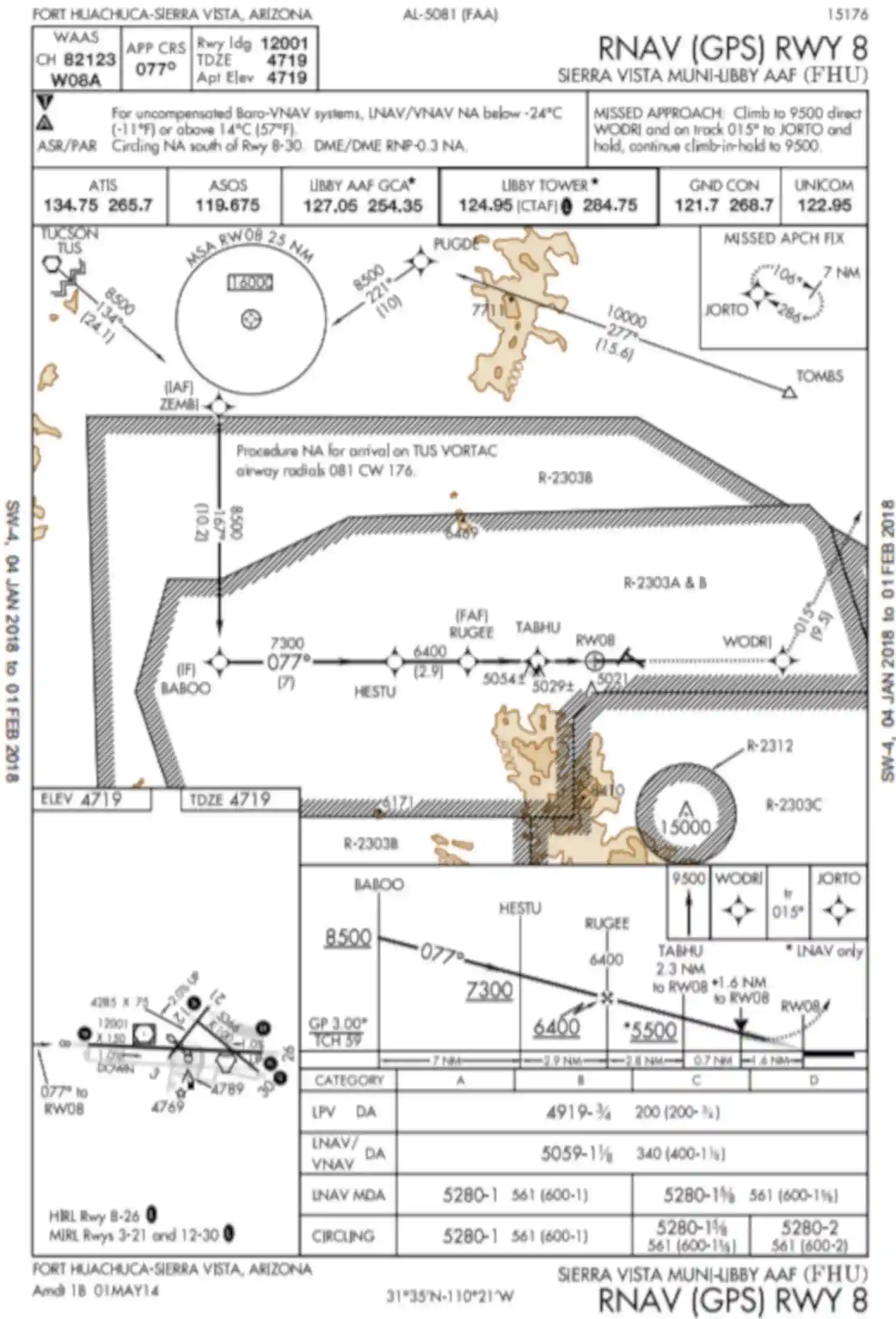
- Overlay procedures are identified by the "name of the procedure" and "or GPS" (e.g., VOR/DME or GPS RWY 15) in the title [Figure 4]
- Authorized procedures must be retrievable from a current onboard navigation database.
- The navigation database may also enhance position orientation by displaying a map containing information on conventional NAVAID approaches.
- This approach information should not be confused with a GPS overlay approach (see the receiver operating manual, AFM, or AFM Supplement for details on how to identify these approaches in the navigation database).
- Overlay approaches do not adhere to the design criteria described in Paragraph 5-4-5m, Area Navigation (RNAV) Instrument Approach Charts, for stand-alone GPS approaches. Overlay approach criteria is based on the design criteria used for ground-based NAVAID approaches.
- Stand-alone approach procedures specifically designed for GPS systems have replaced many of the original overlay approaches.
- All approaches that contain "GPS" in the title (e.g., "VOR or GPS RWY 24," "GPS RWY 24," or "RNAV (GPS) RWY 24") can be flown using GPS.
- GPS-equipped aircraft do not need underlying ground-based NAVAIDs or associated aircraft avionics to fly the approach.
- Monitoring the underlying approach with ground-based NAVAIDs is suggested when able.
- Existing overlay approaches may be requested using the GPS title; for example, the VOR or GPS RWY 24 may be requested as "GPS RWY 24".
- Some GPS procedures have a Terminal Arrival Area (TAA) with an underlining RNAV approach.
- For flight planning purposes, TSOC129() and TSOC196()-equipped users (GPS users) whose navigation systems have fault detection and exclusion (FDE) capability, who perform a preflight RAIM prediction for the approach integrity at the airport where the RNAV (GPS) approach will be flown, and have proper knowledge and any required training and/or approval to conduct a GPSbased IAP, may file based on a GPS-based IAP at either the destination or the alternate airport, but not at both locations
- At the alternate airport, pilots may plan for:
- Lateral navigation (LNAV) or circling minimum descent altitude (MDA);
- LNAV/vertical navigation (LNAV/VNAV) DA, if equipped with and using approved barometric vertical navigation (baroVNAV) equipment;
- RNP 0.3 DA on an RNAV (RNP) IAP, if they are specifically authorized users using approved baroVNAV equipment and the pilot has verified required navigation performance (RNP) availability through an approved prediction program.
- If the above conditions cannot be met, any required alternate airport must have an approved instrument approach procedure other than GPS-based that is anticipated to be operational and available at the estimated time of arrival, and which the aircraft is equipped to fly
-
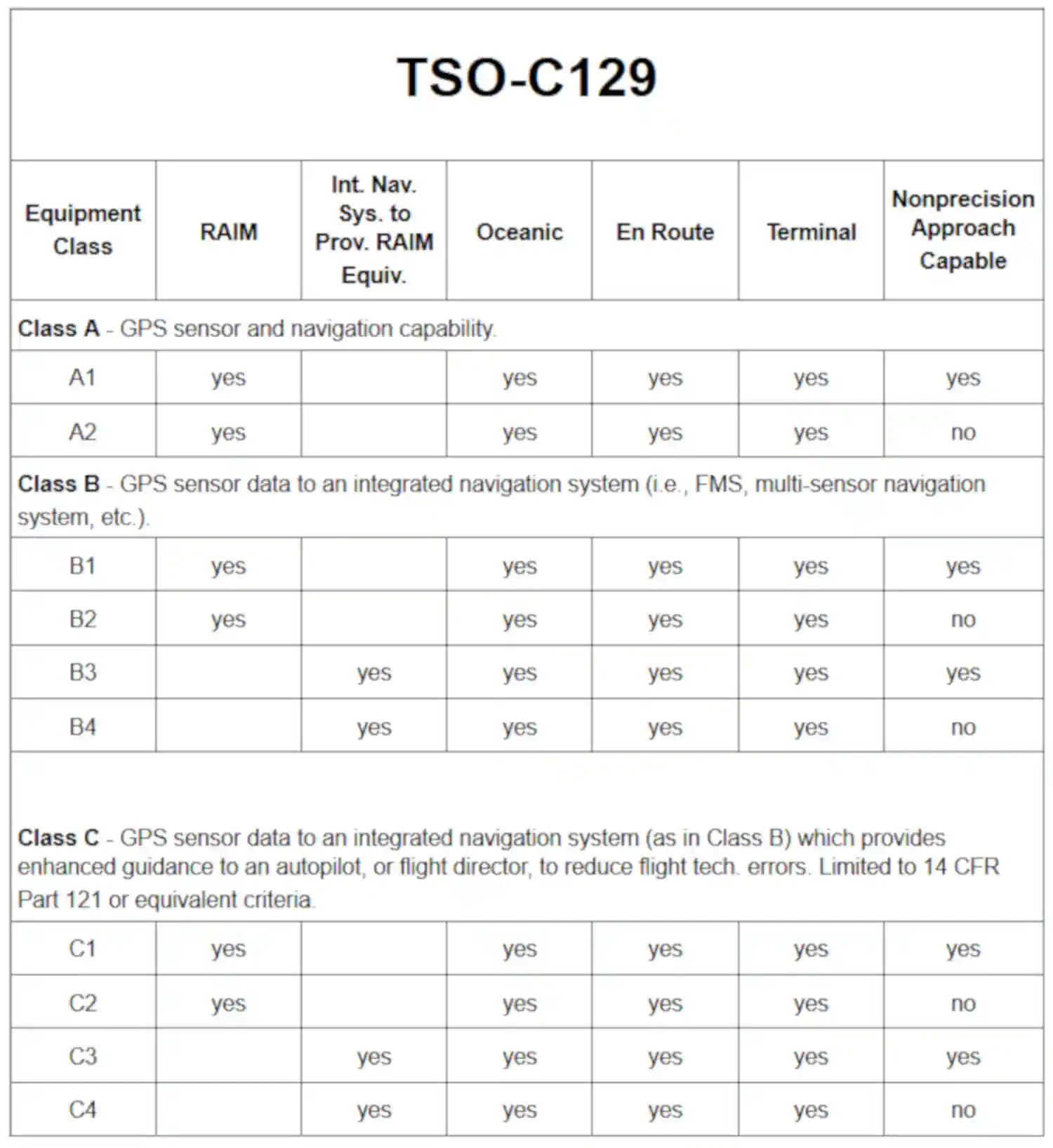
GPS IFR Equipment Classes/Categories -
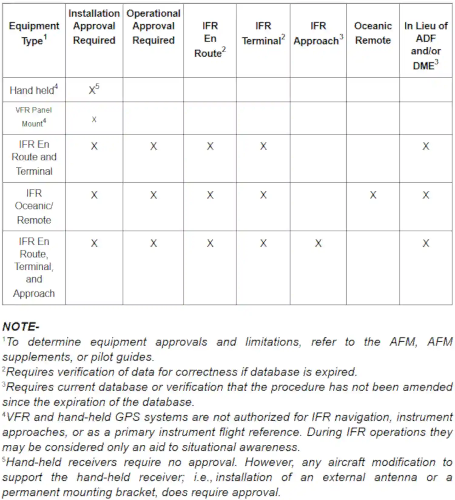
GPS Approval Required/Authorized Use
Procedures for Accomplishing GPS Approaches
- An RNAV (GPS) procedure may be associated with a Terminal Arrival Area (TAA).
- The basic design of the RNAV procedure is the "T" design or a modification of the "T" (See Paragraph 5-4-5d, Terminal Arrival Area (TAA), for complete information).
- Pilots cleared by ATC for an RNAV (GPS) approach should fly the full approach from an Initial Approach Waypoint (IAWP) or feeder fix.
- Randomly joining an approach at an intermediate fix does not assure terrain clearance.
- When an approach has been loaded in the navigation system, GPS receivers will give an "arm" annunciation 30 NM straight line distance from the airport/heliport reference point.
- Pilots should arm the approach mode at this time if not already armed (some receivers arm automatically).
- Without arming, the receiver will not change from en-route CDI and RAIM sensitivity of ±5 NM either side of centerline to ±1 NM terminal sensitivity.
- Where the IAWP is inside this 30 mile point, a CDI sensitivity change will occur once the approach mode is armed and the aircraft is inside 30 NM.
- Where the IAWP is beyond 30 NM from the airport/heliport reference point and the approach is armed, the CDI sensitivity will not change until the aircraft is within 30 miles of the airport/heliport reference point.
- Feeder route obstacle clearance is predicated on the receiver being in terminal (±1 NM) CDI sensitivity and RAIM within 30 NM of the airport/heliport reference point; therefore, the receiver should always be armed (if required) not later than the 30 NM annunciation.
- The pilot must be aware of what bank angle/turn rate the particular receiver uses to compute turn anticipation, and whether wind and airspeed are included in the receiver's calculations.
- This information should be in the receiver operating manual.
- Over or under banking the turn onto the final approach course may significantly delay getting on course and may result in high descent rates to achieve the next segment altitude.
- When within 2 NM of the Final Approach Waypoint (FAWP) with the approach mode armed, the approach mode will switch to active, which results in RAIM and CDI changing to approach sensitivity.
- Beginning 2 NM prior to the FAWP, the full scale CDI sensitivity will smoothly change from ±1 NM to ±0.3 NM at the FAWP.
- As sensitivity changes from ±1 NM to ±0.3 NM approaching the FAWP, with the CDI not centered, the corresponding increase in CDI displacement may give the impression that the aircraft is moving further away from the intended course even though it is on an acceptable intercept heading.
- Referencing the digital track displacement information (cross track error), if it is available in the approach mode, may help the pilot remain position oriented in this situation.
- Being established on the final approach course prior to the beginning of the sensitivity change at 2 NM will help prevent problems in interpreting the CDI display during ramp down.
- Therefore, requesting or accepting vectors which will cause the aircraft to intercept the final approach course within 2 NM of the FAWP is not recommended.
- When receiving vectors to final, most receiver operating manuals suggest placing the receiver in the non-sequencing mode on the FAWP and manually setting the course.
- This provides an extended final approach course in cases where the aircraft is vectored onto the final approach course outside of any existing segment which is aligned with the runway.
- Assigned altitudes must be maintained until established on a published segment of the approach. Required altitudes at waypoints outside the FAWP or stepdown fixes must be considered.
- Calculating the distance to the FAWP may be required in order to descend at the proper location.
- Overriding an automatically selected sensitivity during an approach will cancel the approach mode annunciation.
- If the approach mode is not armed by 2 NM prior to the FAWP, the approach mode will not become active at 2 NM prior to the FAWP, and the equipment will flag.
- In these conditions, the RAIM and CDI sensitivity will not ramp down, and the pilot should not descend to MDA, but fly to the MAWP and execute a missed approach.
- The approach active annunciator and/or the receiver should be checked to ensure the approach mode is active prior to the FAWP.
- Do not attempt to fly an approach unless the procedure in the onboard database is current and identified as "GPS" on the approach chart.
- The navigation database may contain information about non-overlay approach procedures that enhances position orientation generally by providing a map, while flying these approaches using conventional NAVAIDs.
- This approach information should not be confused with a GPS overlay approach (see the receiver operating manual, AFM, or AFM Supplement for details on how to identify these procedures in the navigation database).
- Flying point to point on the approach does not assure compliance with the published approach procedure.
- The proper RAIM sensitivity will not be available and the CDI sensitivity will not automatically change to ±0.3 NM.
- Manually setting CDI sensitivity does not automatically change the RAIM sensitivity on some receivers.
- Some existing non-precision approach procedures cannot be coded for use with GPS and will not be available as overlays.
- Pilots should pay particular attention to the exact operation of their GPS receivers for performing holding patterns and in the case of overlay approaches, operations such as procedure turns.
- These procedures may require manual intervention by the pilot to stop the sequencing of waypoints by the receiver and to resume automatic GPS navigation sequencing once the maneuver is complete.
- The same waypoint may appear in the route of flight more than once consecutively (for example, IAWP, FAWP, MAHWP on a procedure turn).
- Care must be exercised to ensure that the receiver is sequenced to the appropriate waypoint for the segment of the procedure being flown, especially if one or more fly-overs are skipped (for example, FAWP rather than IAWP if the procedure turn is not flown).
- The pilot may have to sequence past one or more fly-overs of the same waypoint in order to start GPS automatic sequencing at the proper place in the sequence of waypoints.
- Incorrect inputs into the GPS receiver are especially critical during approaches.
- In some cases, an incorrect entry can cause the receiver to leave the approach mode.
- A fix on an overlay approach identified by a DME fix will not be in the waypoint sequence on the GPS receiver unless there is a published name assigned to it.
- When a name is assigned, the along track distance (ATD) to the waypoint may be zero rather than the DME stated on the approach chart.
- The pilot should be alert for this on any overlay procedure where the original approach used DME.
- If a visual descent point (VDP) is published, it will not be included in the sequence of waypoints.
- Pilots are expected to use normal piloting techniques for beginning the visual descent, such as ATD.
- Unnamed stepdown fixes in the final approach segment may or may not be coded in the waypoint sequence of the aircraft's navigation database and must be identified using ATD.
- Stepdown fixes in the final approach segment of RNAV (GPS) approaches are being named, in addition to being identified by ATD.
- However, GPS avionics may or may not accommodate waypoints between the FAF and MAP.
- Pilots must know the capabilities of their GPS equipment and continue to identify stepdown fixes using ATD when necessary.
Missed Approach
- A GPS missed approach requires pilot action to sequence the receiver past the MAWP to the missed approach portion of the procedure.
- The pilot must be thoroughly familiar with the activation procedure for the particular GPS receiver installed in the aircraft and must initiate appropriate action after the MAWP.
- Activating the missed approach prior to the MAWP will cause CDI sensitivity to immediately change to terminal (±1NM) sensitivity and the receiver will continue to navigate to the MAWP.
- The receiver will not sequence past the MAWP.
- Turns should not begin prior to the MAWP.
- If the missed approach is not activated, the GPS receiver will display an extension of the inbound final approach course and the ATD will increase from the MAWP until it is manually sequenced after crossing the MAWP.
- Missed approach routings in which the first track is via a course rather than direct to the next waypoint require additional action by the pilot to set the course.
- Being familiar with all of the inputs required is especially critical during this phase of flight.
Receiver Autonomous Integrity Monitoring (RAIM)
- RAIM outages may occur due to an insufficient number of satellites or due to unsuitable satellite geometry which causes the error in the position solution to become too large.
- Loss of satellite reception and RAIM warnings may occur due to aircraft dynamics (changes in pitch or bank angle).
- Antenna location on the aircraft, satellite position relative to the horizon, and aircraft attitude may affect reception of one or more satellites.
- Since the relative positions of the satellites are constantly changing, prior experience with the airport does not guarantee reception at all times, and RAIM availability should always be checked.
- Civilian pilots may obtain GPS RAIM availability information for nonprecision approach procedures by using a manufacturer-supplied RAIM prediction tool, or using the Service Availability Prediction Tool (SAPT) on the FAA en route and terminal RAIM prediction website.
- Pilots can also request GPS RAIM aeronautical information from a flight service station during preflight briefings.
- GPS RAIM aeronautical information can be obtained for a period of 3 hours (for example, if you are scheduled to arrive at 1215 hours, then the GPS RAIM information is available from 1100 to 1400 hours) or a 24-hour timeframe at a particular airport.
- FAA briefers will provide RAIM information for a period of 1 hour before to 1 hour after the ETA hour, unless a specific timeframe is requested by the pilot.
- If flying a published GPS departure, a RAIM prediction should also be requested for the departure airport.
- The military provides airfield specific GPS RAIM NOTAMs for nonprecision approach procedures at military airfields.
- The RAIM outages are issued as M-series NOTAMs and may be obtained for up to 24 hours from the time of request.
- Receiver manufacturers and/or database suppliers may supply "NOTAM" type information concerning database errors.
- Pilots should check these sources when available, to ensure that they have the most current information concerning their electronic database.
- If RAIM is not available, use another type of navigation and approach system; select another route or destination; or delay the trip until RAIM is predicted to be available on arrival.
- On longer flights, pilots should consider rechecking the RAIM prediction for the destination during the flight.
- This may provide an early indication that an unscheduled satellite outage has occurred since takeoff.
- If a RAIM failure/status annunciation occurs prior to the final approach waypoint (FAWP), the approach should not be completed since GPS no longer provides the required integrity.
- The receiver performs a RAIM prediction by 2 NM prior to the FAWP to ensure that RAIM is available as a condition for entering the approach mode.
- The pilot should ensure the receiver has sequenced from "Armed" to "Approach" prior to the FAWP (normally occurs 2 NM prior).
- Failure to sequence may be an indication of the detection of a satellite anomaly, failure to arm the receiver (if required), or other problems which preclude flying the approach.
- If the receiver does not sequence into the approach mode or a RAIM failure/status annunciation occurs prior to the FAWP, the pilot must not initiate the approach nor descend, but instead, proceed to the missed approach waypoint (MAWP) via the FAWP, perform a missed approach, and contact ATC as soon as practical.
- The GPS receiver may continue to operate after a RAIM flag/status annunciation appears, but the navigation information should be considered advisory only.
- Refer to the receiver operating manual for specific indications and instructions associated with loss of RAIM prior to the FAF.
- If the RAIM flag/status annunciation appears after the FAWP, the pilot should initiate a climb and execute the missed approach.
- The GPS receiver may continue to operate after a RAIM flag/status annunciation appears, but the navigation information should be considered advisory only.
- Refer to the receiver operating manual for operating mode information during a RAIM annunciation.
GPS Waypoints
- GPS receivers navigate from one defined point to another retrieved from the aircraft's onboard navigational database.
- These points are waypoints (5-letter pronounceable name), existing VHF intersections, DME fixes with 5-letter pronounceable names and 3-letter NAVAID IDs.
- Each waypoint is a geographical location defined by a latitude/longitude geographic coordinate.
- These 5-letter waypoints, VHF intersections, 5-letter pronounceable DME fixes and 3-letter NAVAID IDs are published on various FAA aeronautical navigation products (IFR Enroute Charts, VFR Charts, Terminal Procedures Publications, etc.)
- A Computer Navigation Fix (CNF) is also a point defined by a latitude/longitude coordinate and is required to support Performance-Based Navigation (PBN) operations.
- The GPS receiver uses CNFs in conjunction with waypoints to navigate from point to point.
- However, CNFs are not recognized by ATC. ATC does not maintain CNFs in their database and they do not use CNFs for any air traffic control purpose.
- CNFs may or may not be charted on FAA aeronautical navigation products, are listed in the chart legends, and are for advisory purposes only.
- Pilots are not to use CNFs for point to point navigation (proceed direct), filing a flight plan, or in aircraft/ATC communications.
- CNFs that do appear on aeronautical charts allow pilots increased situational awareness by identifying points in the aircraft database route of flight with points on the aeronautical chart.
- CNFs are random five-letter identifiers, not pronounceable like waypoints and placed in parenthesis.
- Eventually, all CNFs will begin with the letters "CF" followed by three consonants (for example, CFWBG).
- This five-letter identifier will be found next to an "x" on enroute charts and possibly on an approach chart.
- On instrument approach procedures (charts) in the terminal procedures publication, CNFs may represent unnamed DME fixes, beginning and ending points of DME arcs, and sensor (ground-based signal i.e., VOR, NDB, ILS) final approach fixes on GPS overlay approaches.
- These CNFs provide the GPS with points on the procedure that allow the overlay approach to mirror the ground-based sensor approach.
- These points should only be used by the GPS system for navigation and should not be used by pilots for any other purpose on the approach.
- The CNF concept has not been adopted or recognized by the International Civil Aviation Organization (ICAO).
- GPS approaches use fly-over and fly-by waypoints to join route segments on an approach.
- Fly-by waypoints connect the two segments by allowing the aircraft to turn prior to the current waypoint in order to roll out on course to the next waypoint.
- This is known as turn anticipation and is compensated for in the airspace and terrain clearances.
- The missed approach waypoint (MAWP) will always be a fly-over waypoint.
- A holding waypoint will always be designed as a fly-over waypoint in the navigational database but may be charted as a fly-by event unless the holding waypoint is used for another purpose in the procedure and both events require the waypoint to be a fly-over event.
- Some waypoints may have dual use; for example, as a fly-by waypoint when used as an IF for a NoPT route and as a fly-over waypoint when the same waypoint is also used as an IAF/IF hold-in-lieu of PT.
- Since the waypoint can only be charted one way, when this situation occurs, the fly-by waypoint symbol will be charted in all uses of the waypoint.
- Unnamed waypoints for each airport will be uniquely identified in the database.
- Although the identifier may be used at different airports (for example, RW36 will be the identifier at each airport with a runway 36), the actual point, at each airport, is defined by a specific latitude/longitude coordinate.
- The runway threshold waypoint, normally the MAWP, may have a five-letter identifier (for example, SNEEZ) or be coded as RW## (for example, RW36, RW36L).
- MAWPs located at the runway threshold are being changed to the RW## identifier, while MAWPs not located at the threshold will have a five-letter identifier.
- This may cause the approach chart to differ from the aircraft database until all changes are complete.
- The runway threshold waypoint is also used as the center of the Minimum Safe Altitude (MSA) on most GPS approaches.
-
Position Orientation:
- Pilots should pay particular attention to position orientation while using GPS.
- Distance and track information are provided to the next active waypoint, not to a fixed navigation aid.
- Receivers may sequence when the pilot is not flying along an active route, such as when being vectored or deviating for weather, due to the proximity to another waypoint in the route.
- This can be prevented by placing the receiver in the non-sequencing mode.
- When the receiver is in the non-sequencing mode, bearing and distance are provided to the selected waypoint and the receiver will not sequence to the next waypoint in the route until placed back in the auto sequence mode or the pilot selects a different waypoint.
- The pilot may have to compute the ATD to stepdown fixes and other points on overlay approaches, due to the receiver showing ATD to the next waypoint rather than DME to the VOR or ILS ground station.
-
Impact of Magnetic Variation on PBN Systems:
- Differences may exist between PBN systems and the charted magnetic courses on ground-based NAVAID instrument flight procedures (IFP), enroute charts, approach charts, and Standard Instrument Departure/Standard Terminal Arrival (SID/STAR) charts. These differences are due to the magnetic variance used to calculate the magnetic course. Every leg of an instrument procedure is first computed along a desired ground track with reference to true north. A magnetic variation correction is then applied to the true course in order to calculate a magnetic course for publication. The type of procedure will determine what magnetic variation value is added to the true course. A ground-based NAVAID IFP applies the facility magnetic variation of record to the true course to get the charted magnetic course. Magnetic courses on PBN procedures are calculated two different ways. SID/STAR procedures use the airport magnetic variation of record, while IFR enroute charts use magnetic reference bearing. PBN systems make a correction to true north by adding a magnetic variation calculated with an algorithm based on aircraft position, or by adding the magnetic variation coded in their navigational database. This may result in the PBN system and the procedure designer using a different magnetic variation, which causes the magnetic course displayed by the PBN system and the magnetic course charted on the IFP plate to be different. It is important to understand, however, that PBN systems, (with the exception of VOR/DME RNAV equipment) navigate by reference to true north and display magnetic course only for pilot reference. As such, a properly functioning PBN system, containing a current and accurate navigational database, should fly the correct ground track for any loaded instrument procedure, despite differences in displayed magnetic course that may be attributed to magnetic variation application. Should significant differences between the approach chart and the PBN system avionics' application of the navigation database arise, the published approach chart, supplemented by NOTAMs, holds precedence.
- The course into a waypoint may not always be 180 degrees different from the course leaving the previous waypoint, due to the PBN system avionics' computation of geodesic paths, distance between waypoints, and differences in magnetic variation application. Variations in distances may also occur since PBN system distance-to-waypoint values are ATDs computed to the next waypoint and the DME values published on underlying procedures are slant-range distances measured to the station. This difference increases with aircraft altitude and proximity to the NAVAID.
-
GPS Familiarization:
- Pilots should practice GPS approaches in visual meteorological conditions (VMC) until thoroughly proficient with all aspects of their equipment prior to attempting flight in instrument meteorological conditions (IMC).
- Pilots should be proficient in the following areas:
- Using the receiver autonomous integrity monitoring (RAIM) prediction function;
- Inserting a DP into the flight plan, including setting terminal CDI sensitivity, if required, and the conditions under which terminal RAIM is available for departure;
- Programming the destination airport;
- Programming and flying the approaches (especially procedure turns and arcs);
- Changing to another approach after selecting an approach;
- Programming and flying "direct" missed approaches;
- Programming and flying "routed" missed approaches;
- Entering, flying, and exiting holding patterns, particularly on approaches with a second waypoint in the holding pattern;
- Programming and flying a "route" from a holding pattern;
- Programming and flying an approach with radar vectors to the intermediate segment;
- Indication of the actions required for RAIM failure both before and after the FAWP; and.
- Programming a radial and distance from a VOR (often used in departure instructions).
GPS Approach Considerations
- Know your equipment, its operation, and limitations
- If cleared to an approach fix not loaded into the system, consider requesting vectors if more time to load is needed
- Load the expected approach as soon as possible to alleviate work later.
- If the approach changes later, you still have time to correct
- Compare approach plate to system load, to include the use of any holds
- If receiving vectors, activate vectors to finals.
- If stepdown fixes are eliminated by selecting vectors to final, consider not activating vectors and instead activating the specific leg of the approach.
- Verify the CDI source is set to the appropriate system
- Monitor the annunicators to verify as expected
Global Positioning System Instrument Approaches Knowledge Check
Private Pilot

Core Knowledge Review
Review the foundational knowledge, key concepts, and practical considerations for Global Positioning System Instrument Approaches.
Foundational
Immediate Feedback
Answer Explanations
Commercial Pilot

Advanced Application
Apply your knowledge of Global Positioning System Instrument Approaches to advanced operational scenarios, risk management, and aeronautical decision-making.
Advanced
Scenario Based
Risk Management
Why Take a Quiz?
Quizzes reinforce key concepts, identify knowledge gaps, and build confidence for real-world decisions in the cockpit. Quiz material is representative of the information provided here and is not based on or sourced from the Federal Aviation Administration test bank.
Global Positioning System Instrument Approaches Interactive Scenario
Interactive Scenario
Loading scenario details...
Decision 1
0%
Scenario Complete
Global Positioning System Instrument Approaches Conclusion
- Pilots can visit the FAA's Instrument Flight Procedures Information Gateway to review and submit questions related to the how and why certain procedures are as they are
- Still looking for something? Continue searching: