Attitude Indicator
The attitude indicator is a type of instrument used to reference the aircraft's pitch and bank about an artificial horizon.
Introduction to Attitude Indicator
- The attitude indicator, originally called the Artificial Horizon Indicator, is an instrument that references the aircraft's pitch and bank against an artificial horizon utilizing a gyroscopic system.
- Although electric versions are available, the instrument generally uses the vacuum/gyroscopic system to spin the gyroscopes.
- It operates on the principle of rigidity in space, which gives an immediate and direct indication of the aircraft's orientation.
- Attitude indicators, however, are not without their inaccuracies and errors.
- Preflight actions minimize the chance of inaccurate information.
- As with any system or instrument, anomalies and malfunctions are possible, requiring detailed knowledge of the indicator and related systems.
Attitude Indicator Key Highlights
- The attitude indicator displays aircraft pitch and bank information relative to the horizon during flight operations.
- Attitude indicators improve aircraft control and situational awareness, especially during instrument meteorological conditions.
- Traditional attitude indicators use gyroscopic principles to maintain a stable reference independent of aircraft movement.
- Modern glass cockpit systems often provide electronic attitude information through integrated flight displays and AHRS technology.
- The miniature aircraft symbol and horizon bar help pilots maintain proper aircraft attitude and orientation.
- Attitude indicators are essential for instrument flying and recovery from unusual attitudes or reduced-visibility conditions.
- Gyroscopic precession, acceleration errors, or system malfunctions can affect attitude indicator accuracy and reliability.
- Pilots should cross-check attitude information with supporting flight instruments to verify aircraft performance and orientation.
- Vacuum system failures or electrical malfunctions may cause attitude indicator degradation depending on aircraft design.
- Understanding attitude indicator operation improves instrument proficiency, aircraft control, and overall flight safety.
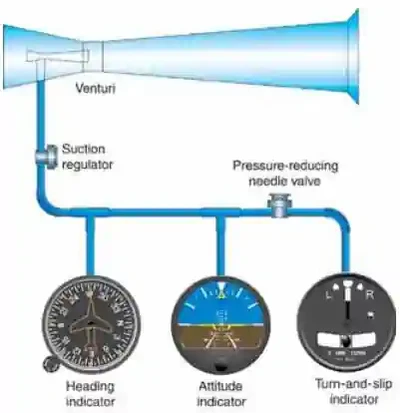
Gyroscope Systems
- Flight without reference to a visible horizon can be safely accomplished by the use of gyroscopic instrument systems.
- These systems include attitude, heading, and rate instruments, along with their power sources.
- These gyroscopes are powered by either the electrical or a vacuum system. []
- These instruments include a gyroscope (or gyro) that is a small wheel with its weight concentrated around its periphery.
- Characteristics of gyroscopes:
- Rigidity.
- Precession.
- Rigidity:
- When this wheel is spun at high speed, it becomes rigid and resists tilting or turning in any direction other than around its spin axis.
- Attitude and heading instruments operate on the principle of rigidity.
- For these instruments, the gyro remains rigid in its case and the aircraft rotates about it.
- Precession:
- Rate indicators, such as turn indicators and turn coordinators, operate on the principle of precession.
- In this case, the gyro processes (or rolls over) proportionate to the rate the aircraft rotates about one or more of its axes.

Attitude Indicator Design and Function
- The attitude indicator's operating mechanism is a gyroscope with a vertical spin axis.
- It is spun at high speed by either a stream of air impinging on buckets cut into its periphery or by an electric motor.
- The gyroscope mounts in a double gimbal, which allows the aircraft to pitch and roll about the gyro as it remains fixed in space.
- A horizon disk is attached to the gimbals so it remains in the same plane as the gyro, and the aircraft pitches and rolls about it.
- A miniature aircraft is connected to the aircraft while the gyro (horizon) remains in place. []
- The aircraft rotates around the instrument.
- A knob at the bottom center of the instrument case raises or lowers the aircraft to compensate for pitch trim changes as the airspeed changes.
- The width of the wings of the symbolic aircraft and the dot in the center of the wings represent a pitch change of approximately 2°.
- Some attitude indicators are caged.
- Newer instruments do not have these restrictive tumble limits; therefore, they do not have a caging mechanism.
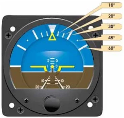
- The top half of the instrument dial and horizon disc is blue, representing the sky, and the bottom half is brown, representing the ground.
- Displays pitch from artificial horizon line in degrees (long lines: 10°, short: 5°).
- Displays roll from bank index in degrees (10°, 20°, 30°, 60°). []
- Important for IFR but only minimal importance in VFR flight as the outside world is your attitude indicator.
- Pendulous vanes act undesirably with a turn because G's are not felt down the axis of rotation, causing precession.
- Must erect itself; on the ground, it uses gravity; in the air, it uses pendulous vanes.
- Designed for a 360° roll and 85° pitch.
- By referencing the miniature airplane and the artificial horizon, the pilot can tell if he is flying level or in a banked or climbing turn.
- For an AI to function properly, the gyro must remain vertically upright while the aircraft rolls and pitches around it.
- The bearings in these instruments have a minimum of friction; however, even this small amount places a restraint on the gyro producing precession and causing the gyro to tilt.
- To minimize this tilting, an erection mechanism inside the instrument case applies force whenever the gyro tilts from its vertical position.
- This force acts in such a way to return the spinning wheel to its upright position.
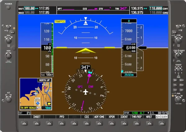
- In a glass cockpit configuration, the attitude indicator uses the Inertial Reference Unit (IRU), Inertial Navigation System (INS), and Attitude Heading Reference System (AHRS).


Attitude Indicator Inaccuracies & Errors
- Attitude indicators are generally free from most errors.
- Uses pendulous vanes to correct for banking errors.
- Can tumble if 100-110° of bank or 60-70° of pitch is exceeded.
- May be caged preventing tumbling, especially during acrobatics.
- Accelerations may cause a slight pitch up indication.
- Decelerations may cause a slight pitch down indication.
- This erection can take as long as 5 minutes, but is normally done within 2 to 3 minutes.
- Attitude indicators are free from most errors, but depending upon the speed with which the erection system functions, there may be a slight nose-up indication during a rapid acceleration and a nose-down indication during a rapid deceleration.
- There is also a possibility of a small bank angle and pitch error after a 180° turn.
- These inherent errors are small and correct themselves within a minute or so after returning to straight-and-level flight.
- The older artificial horizons were limited in the amount of pitch or roll they could tolerate, normally about 60° in pitch and 100° in roll.
- After either of these limits was exceeded, the gyro housing contacted the gimbals, applying such a precessing force that the gyro tumbled.
- Because of this limitation, these instruments had a caging mechanism that locked the gyro in its vertical position during any maneuvers that exceeded the instrument limits.
Attitude Indicator Preflight Action
- When an aircraft engine is first started and pneumatic or electric power is supplied to the instruments, the gyro is not erect.
- A self-erecting mechanism inside the instrument actuated by the force of gravity applies a precessing force, causing the gyro to rise to its vertical position.
- The attitude indicator should not bank more than 5° in taxi turns.
Attitude Indicator Anamolies & Malfunctions
- Attitude indicators may fail internally or due to a vacuum system failure.
- A physical failure may manifest with the indicator becoming stuck.
- A vacuum failure may manifest with the instrument acting erratically.
Inertial Reference Unit (IRU), Inertial Navigation System (INS), and Attitude Heading Reference System (AHRS)
- Modern aircraft increasingly use IRUs, INS' and AHRS systems, particularly glass cockpit setups. []
- IRUs are self-contained systems comprised of gyros and accelerometers that provide aircraft attitude (pitch, roll, and heading), position, and velocity information in response to signals resulting from inertial effects on system components.
- Once aligned with a known position, IRUs continuously calculate position and velocity. IRU position accuracy decays with time.
- This degradation is known as "drift".
- INSs combine the components of an IRU with an internal navigation computer.
- By programming a series of waypoints, these systems will navigate along a predetermined track.
- AHRSs are electronic devices that provide attitude information to aircraft systems such as weather radar and autopilot, but do not directly compute position information.
- Aircraft equipped with slaved compass systems may be susceptible to heading errors caused by exposure to magnetic field disturbances (flux fields) found in materials that are commonly located on the surface or buried under taxiways and ramps.
- These materials generate a magnetic flux field that can be sensed by the aircraft's compass system flux detector or "gate", which can cause the aircraft's system to align with the material's magnetic field rather than the earth's natural magnetic field.
- The system's erroneous heading may not self-correct.
- Prior to take off pilots should be aware that a heading misalignment may have occurred during taxi.
- Pilots are encouraged to follow the manufacturer's or other appropriate procedures to correct possible heading misalignment before take off is commenced.

Attitude Indicator Knowledge Check


Attitude Indicator Conclusion
- Always keep in mind the effects of parallax error.
- Still looking for something? Continue searching:
Attitude Indicator References
- Federal Aviation Administration - Pilot/Controller Glossary.
- Aeronautical Information Manual (1-1-15) Inertial Reference Unit (IRU), Inertial Navigation System (INS), and Attitude Heading Reference System (AHRS).
- CFI Notebook.net - Gyroscopic Systems.
- Instrument Flying Handbook (3-18) Attitude Indicators.