Pitot Static & Vacuum Systems
Pitot-static and vacuum systems power essential flight instruments and require pilots to recognize blockages, leaks, and system failures.
Introduction to Pitot Static & Vacuum Systems
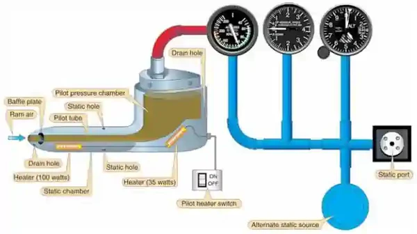
- The Pitot-static system measures and compares air pressures from the Pitot tube and static port.
- These measurements are used to display indications for the Airspeed Indicator (ASI), Altimeter, and Vertical Speed Indicators (VSI).
- Vacuum and pressure systems rely on negative (vacuum) or positive (pressure) pressures to spin gyroscopes
- Pumps in the "back" of the system create vacuum, while pumps in the "front" the system create pressure.
- Directional gyros are almost all air-driven by evacuating the case and allowing filtered air to flow into the case and out through a nozzle, blowing against buckets cut in the periphery of the wheel
- Vacuum systems can malfunction, causing abnormalities or complete failures of associated systems
Pitot Static & Vacuum Systems Key Highlights
- Pitot-static and vacuum systems provide critical information and instrument operation support for aircraft flight instruments.
- The pitot-static system supplies pressure information used by the airspeed indicator, altimeter, and vertical speed indicator.
- Pitot pressure measures ram air pressure while static pressure reflects ambient atmospheric pressure surrounding the aircraft.
- Blockages or leaks within the pitot-static system can cause inaccurate instrument indications and hazardous flight conditions.
- Pitot heat systems help prevent ice accumulation that could obstruct pitot tube airflow during icing conditions.
- Vacuum systems commonly power gyroscopic instruments such as the attitude indicator and heading indicator in many aircraft.
- Vacuum pump failures can result in loss of gyroscopic instrument reliability and increased pilot workload.
- Pilots should monitor instrument indications carefully for signs of pitot-static or vacuum system malfunctions during flight.
- Modern aircraft may replace traditional vacuum systems with electrically powered or glass cockpit instrumentation systems.
- Understanding pitot-static and vacuum systems improves systems knowledge, instrument interpretation, and overall flight safety.
Pitot-Static System
- Pitot Static systems measure and compare air pressures from the Pitot tube and static port
- These measurements display indications for the Airspeed Indicator (ASI), Altimeter, and Vertical Speed Indicators (VSI).
- The system consists of two components:
-
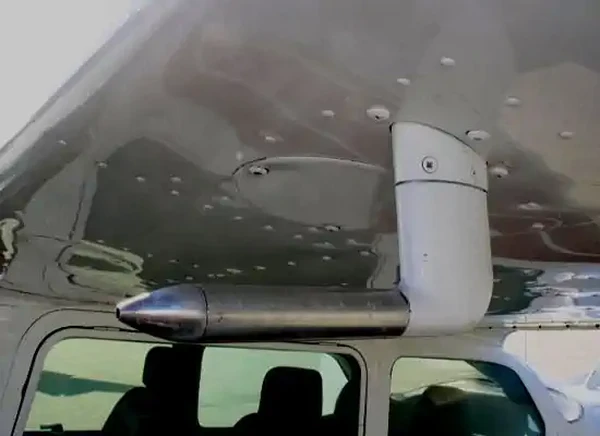
Pitot Tube:
- Invented by Henri Pitot in 1732, the Pitot tube measures fluid flow (air) velocity.
- The device measures ram (forced) air through a small hole in its front.
- The device's placement is often on the front of the aircraft or an airfoil to capture smooth (undisturbed) air. []
- The ram air captured produces an airspeed reading on the airspeed indicator (ASI).
-
Pitot Heat:
- Pitot Tubes are often electrically heated, which can prevent and remove ice accumulation. []
- Note that these devices should only be utilized during ground operations when necessary.
- Leaving them on unnecessarily can cause heat to the point of damage/malfunction.
- When airborne, the airflow otherwise cools the device.
-
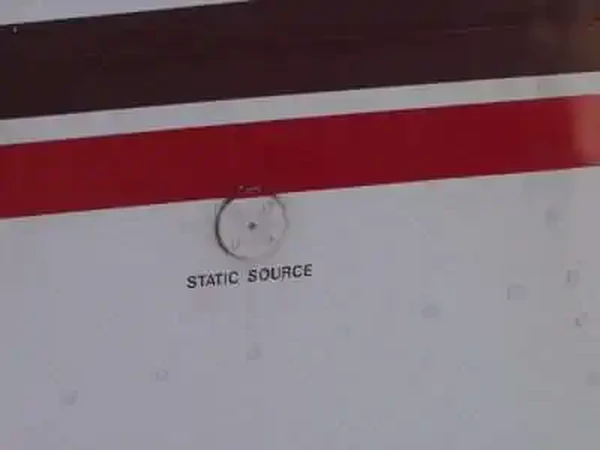
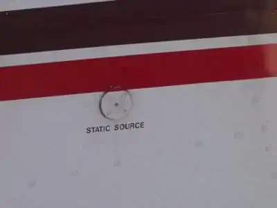
Static Port:
- Static ports measure ambient still-air atmospheric pressure.
- Typically, ports are flush mounted on the side of the aircraft where air is undisturbed. []
- Some aircraft may utilize heated static ports to mitigate ice.
- Dual ports remove errors due to slips and skids.
- Responsible for Airspeed Indicator, Altimeter, and Vertical Speed Indicators.
- The POH/AFM contains any corrections to the airspeed for the various flaps and landing gear configurations.
-
Alternate Static Source:
- An alternate static air source valve is available for emergencies on some aircraft.
- If the alternate source ports inside the airplane, where static pressure is usually lower than outside, selection may result in the following erroneous instrument indications:
- The altimeter reads higher than normal.
- Indicated airspeed (IAS) reads greater than normal.
- VSI momentarily shows a climb.
- Many POHs provide a correction table and aircraft-specific instructions.
- The alternate static source is not corrected for non-standard pressure (as with an altimeter's Kollsman window).
- Using alternate static sources may impact other instruments that rely on static pressure (i.e., autopilots, TCAS, transponder, etc.).
- Using alternate static sources can also decrease the accuracy beyond the 75 feet recommendation outlined in the Aeronautical Information Manual.


Vacuum and Pressure Systems
- Gyroscopes power several flight instruments.
- In some aircraft, all the gyros are vacuum, pressure, or electrically operated.
- In other aircraft, vacuum or pressure systems provide the power for the heading and attitude indicators, while the electrical system provides the power for the turn coordinator.
- Most aircraft have at least two sources of power to ensure at least one source of bank information is available if one power source fails.
- The vacuum or pressure system spins the gyro by drawing a stream of air against the rotor vanes to spin the rotor at high speed, much like a waterwheel or turbine operation.
- The vacuum or pressure required for instrument operation varies but is usually between 4.5 "Hg and 5.5 "Hg.
- One source of vacuum for the gyros is a vane-type engine-driven pump mounted on the engine's accessory case.
- Pump capacity varies in different aircraft, depending on the number of gyros.
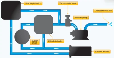
- A typical vacuum system consists of an engine-driven pump, relief valve, air filter, gauge, and tubing necessary to complete the connections. The gauge is mounted in the aircraft's instrument panel and indicates the amount of pressure in the system (measured in inches of mercury less than ambient pressure).
- Air is drawn into the vacuum system by the engine-driven vacuum pump. []
- It first goes through a filter, which prevents foreign matter from entering the vacuum or pressure system.
- The air then moves through the attitude and heading indicators, which causes the gyros to spin.
- A relief valve prevents the vacuum pressure, or suction, from exceeding prescribed limits.
- After that, the air is expelled overboard or used in other systems, such as for inflating pneumatic deicing boots.
- Monitoring vacuum pressure during flight is important because the attitude and heading indicators may not provide reliable information when suction pressure is low.
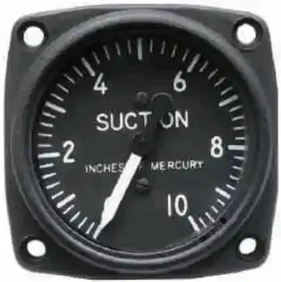
- The vacuum, or suction, gauge is generally marked to indicate the normal range. []
- Some aircraft have a warning light that illuminates when the vacuum pressure drops below the acceptable level.
- The gyroscopic instruments may become unstable and inaccurate when the vacuum pressure drops below the normal operating range.
- Routinely cross-checking the instruments is a good habit to develop.
-
Vacuum Pump Systems:
-
Wet-Type Vacuum Pump:
- Steel-vane air pumps have been used for many years to evacuate the instrument cases. []
- The vanes in these pumps are lubricated by a small amount of engine oil metered into the pump and discharged with the air
- In some aircraft the discharge air is used to inflate rubber deicer boots on the wing and empennage leading edges
- To keep the oil from deteriorating the rubber boots, it must be removed with an oil separator like the one in Figure 3-28
- The vacuum pump moves a greater volume of air than is needed to supply the instruments with the suction needed, so a suction-relief valve is installed in the inlet side of the pump
- This spring-loaded valve draws in just enough air to maintain the required low pressure inside the instruments, as is shown on the suction gauge in the instrument panel
- Filtered air enters the instrument cases from a central air filter
- As long as aircraft fly at relatively low altitudes, enough air is drawn into the instrument cases to spin the gyros at a sufficiently high speed
-
Dry Air Vacuum Pump:
- As flight altitudes increase, the air is less dense and more air must be forced through the instruments. []
- Air pumps that do not mix oil with the discharge air are used in high flying aircraft
- Steel vanes sliding in a steel housing need to be lubricated, but vanes made of a special formulation of carbon sliding inside carbon housing provide their own lubrication in a microscopic amount as they wear
-

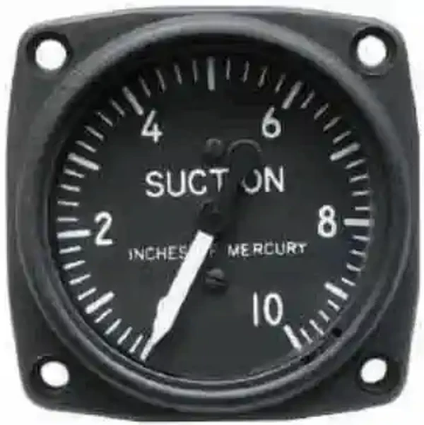

Vacuum Pressure
- Gyro pressure gauge, vacuum gauge, or suction gauge are all terms for the same gauge used to monitor the vacuum developed in the system that actuates the air driven gyroscopic flight instruments
- Air is pulled through the instruments, causing gyroscopes to spin
- The speed at which the gyros spin needs to be within a certain range for correct operation
- This speed is directly related to the suction pressure that is developed in the system
- The suction gauge is extremely important in aircraft relying solely on vacuum operated gyroscopic flight instruments
- Vacuum is a differential pressure indication, meaning the pressure to be measured is compared to atmospheric pressure through the use of a sealed diaphragm or capsule
- The gauge is calibrated in inches of mercury
- It shows how much less pressure exists in the system than in the atmosphere
Vacuum System Instruments
- Depending on instrument design, vacuum pumps may be used on the operation of the turn coordinator, attitude indicator, and heading indicator.
-
Attitude Indicator Failure:
- Attitude indicators may fail internally or due to a vacuum system failure.
- A physical failure may manifest with the indicator becoming stuck
- A vacuum failure may manifest with the instrument acting erratically
-
Vacuum System Failures:
- Vacuum systems are recognized by a low indication on the vacuum gauge or unusual instrument indications
- Reduces or eliminates effectiveness of the turn coordinator, attitude indicator, and heading indicator
- When the primary air inlet is blocked, the backup inlet automatically opens due to pressure
- Occurs when the vacuum pump fails or when both intakes are blocked
-
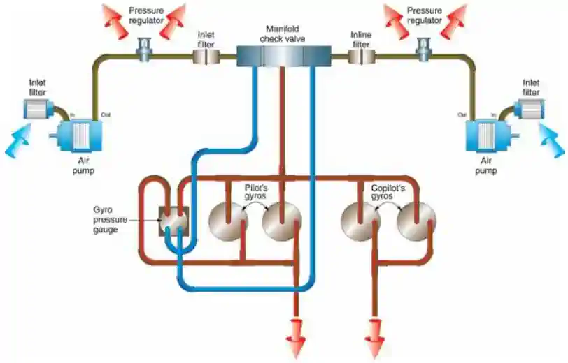
Pressure Systems:
- Two dry air pumps are used with filters in their inlet to filter out any contaminants that could damage the fragile carbon vanes in the pump
- The discharge air from the pump flows through a regulator, where excess air is bled off to maintain the pressure in the system at the desired level
- The regulated air then flows through in-line filters to remove any contamination that could have been picked up from the pump, and from there into a manifold check valve
- If either engine should become inoperative or either pump should fail, the check valve isolates the inoperative system and the instruments are driven by air from the operating system
- After the air passes through the instruments and drives the gyros, it is exhausted from the case
- The gyro pressure gauge measures the pressure drop across the instruments
Gyroscope Characteristics
- Flight without reference to a visible horizon can be safely accomplished by the use of gyroscopic instrument systems.
- These systems include attitude, heading, and rate instruments, along with their power sources.
- These gyroscopes are powered by either the electrical or a vacuum system. []
- These instruments include a gyroscope (or gyro) that is a small wheel with its weight concentrated around its periphery.
- Characteristics of gyroscopes:
- Rigidity
- Precession
- Rigidity:
- When this wheel is spun at high speed, it becomes rigid and resists tilting or turning in any direction other than around its spin axis
- Attitude and heading instruments operate on the principle of rigidity
- For these instruments, the gyro remains rigid in its case and the aircraft rotates about it
- Precession:
- Rate indicators, such as turn indicators and turn coordinators, operate on the principle of precession
- In this case, the gyro processes (or rolls over) proportionate to the rate the aircraft rotates about one or more of its axes

Power Sources
- Power Sources Aircraft and instrument manufacturers have designed redundancy in the flight instruments so that any single failure will not deprive the pilot of the ability to safely conclude the flight
- Gyroscopic instruments are crucial for instrument flight; therefore, they are powered by separate electrical or pneumatic sources
-
Electrical Power Sources:
- Many general aviation aircraft that use pneumatic attitude indicators use electric rate indicators and/or the reverse
- Some instruments identify their power source on their dial, but it is extremely important that pilots consult the POH/AFM to determine the power source of all instruments to know what action to take in the event of an instrument failure
- Direct current (D.C.) electrical instruments are available in 14- or 28-volt models, depending upon the electrical system in the aircraft
- A.C. is used to operate some attitude gyros and autopilots
- Aircraft with only D.C. electrical systems can use A.C. instruments via installation of a solid-state D.C. to A.C. inverter, which changes 14 or 28 volts D.C. into three-phase 115-volt, 400-Hz A.C.
-
Pneumatic Power Sources:
- Pneumatic Systems Pneumatic gyros are driven by a jet of air impinging on buckets cut into the periphery of the wheel
- On many aircraft this stream of air is obtained by evacuating the instrument case with a vacuum source and allowing filtered air to flow into the case through a nozzle to spin the wheel
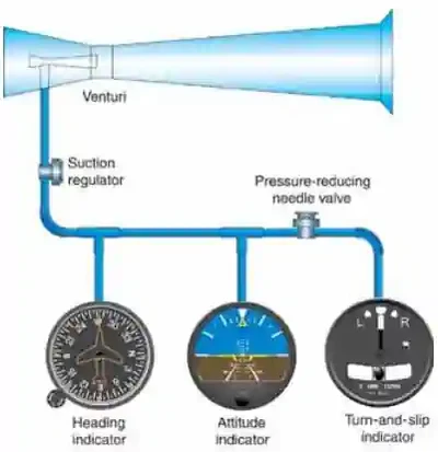
- Venturi Tube Systems Aircraft that do not have a pneumatic pump to evacuate the instrument case can use venturi tubes mounted on the outside of the aircraft, similar to the system shown in Figure 3-27
- Air flowing through the venturi tube speeds up in the narrowest part and, according to Bernoulli's principle, the pressure drops
- This location is connected to the instrument case by a piece of tubing
- The two attitude instruments operate on approximately 4" Hg of suction; the turn-and-slip indicator needs only 2" Hg, so a pressure-reducing needle valve is used to decrease the suction
- Air flows into the instruments through filters built into the instrument cases
- In this system, ice can clog the venturi tube and stop the instruments when they are most needed
Common Training Aircraft Pitot-Static System Characteristics
-
Cessna 172:
- Composed of a heated Pitot tube on the lower surface of the left wing
- An external static port is located on the lower left side of the forward fuselage
- Pitot Tube consists of a heating element, a 5-amp switch/breaker, and associated wiring
- Alternate static (below throttle) provides pressure from inside the cabin
-
Piper Arrow:
- Composed of a heated Pitot tube on the lower left wing
- Two static ports are located on each side of the fuselage
- Alternate static air (below the pilot control yoke) provides static pressure from inside the cabin
Common Training Aircraft Vacuum System Characteristics
-
Cessna-172:
- Provides "power" to the attitude indicator and directional indicator.
- The desired suction range is 4.5 to 5.5 inches Hg.
- Transducers measure vacuum output at each pump.
- If output of the left or right pump drops below 3.0 in. HG then L VAC R will flash for 10 seconds before becoming steady.
- There are 2 engine driven vacuum pumps.
-
Piper Arrow:
- Protected by a vacuum regulator (protects gyros).
- Normal operation reads 4.8 to 5.1 inches of mercury.
- "Powers" air driven gyro instruments.
- Vacuum pump is a dry type pump.
- Zero pressure may indicate a sheered pump drive.
- Reduction in pressures may indicate dirty filters and screens.
Pitot-Static System Anomalies and Malfunctions
- .
Inertial Reference Unit (IRU), Inertial Navigation System (INS), and Attitude Heading Reference System (AHRS)
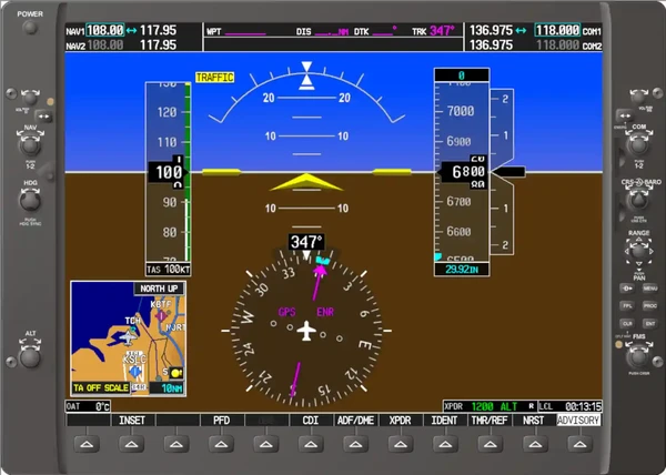
- Modern aircraft increasingly use IRUs, INS' and AHRS systems, particularly glass cockpit setups. []
- IRUs are self-contained systems comprised of gyros and accelerometers that provide aircraft attitude (pitch, roll, and heading), position, and velocity information in response to signals resulting from inertial effects on system components.
- Once aligned with a known position, IRUs continuously calculate position and velocity. IRU position accuracy decays with time.
- This degradation is known as "drift".
- INSs combine the components of an IRU with an internal navigation computer.
- By programming a series of waypoints, these systems will navigate along a predetermined track.
- AHRSs are electronic devices that provide attitude information to aircraft systems such as weather radar and autopilot, but do not directly compute position information.
- Aircraft equipped with slaved compass systems may be susceptible to heading errors caused by exposure to magnetic field disturbances (flux fields) found in materials that are commonly located on the surface or buried under taxiways and ramps.
- These materials generate a magnetic flux field that can be sensed by the aircraft's compass system flux detector or "gate", which can cause the aircraft's system to align with the material's magnetic field rather than the earth's natural magnetic field.
- The system's erroneous heading may not self-correct.
- Prior to take off pilots should be aware that a heading misalignment may have occurred during taxi.
- Pilots are encouraged to follow the manufacturer's or other appropriate procedures to correct possible heading misalignment before take off is commenced.

Pitot Static & Vacuum Systems Interactive Scenario
Interactive Scenario
Loading scenario details...
Decision 1
0%
Scenario Complete
Vacuum System Lessons & Case Studies
Pitot Static & Vacuum Systems Knowledge Check
Private Pilot

Core Knowledge Review
Review the foundational knowledge, key concepts, and practical considerations for Pitot Static & Vacuum Systems.
Foundational
Immediate Feedback
Answer Explanations
Commercial Pilot

Advanced Application
Apply your knowledge of Pitot Static & Vacuum Systems to advanced operational scenarios, risk management, and aeronautical decision-making.
Advanced
Scenario Based
Risk Management
Why Take a Quiz?
Quizzes reinforce key concepts, identify knowledge gaps, and build confidence for real-world decisions in the cockpit.
Pitot Static & Vacuum Systems Conclusion
- The vacuum system is an important component for many aircraft as it runs instrumentation and potentially other systems
- Of note however, is that these systems can be expensive to maintain and there is the option to run many if not all of the systems requiring vacuum on electric
- Still looking for something? Continue searching:
Pitot Static & Vacuum Systems References
- AOPA - Single-Point Failure Accident Case Study.
- Federal Aviation Administration - Pilot/Controller Glossary.
- Advisory Circular (43.13-1B CHG 1) Acceptable Methods, Techniques, and Practices - Aircraft Inspection and Repair.
- FAA - Aviation Maintenance Technician Handbook.
- AvWeb - Dumping Vacuum for Electric.
- CFI Notebook.net - Attitude Indicator.
- CFI Notebook.net - Heading Indicator.
- CFI Notebook.net - Pilot Information Manual.
- CFI Notebook.net - Turn Coordinator.
- Instrument Flying Handbook (3-19) Heading Indicators.