Aircraft Landing Gear
Landing gear systems provide critical structural aircraft load support during taxi, takeoff, and landing operations.
Introduction to Aircraft Landing Gear
- Landing gear systems support critical structural aircraft load during taxi, takeoff, and landing operations
- Several types of landing gear have been designed for the intended operation or desired performance
- Landing gear varies in complexity, resulting in different components & equipment necessary for operation
- A sub-system to the landing gear is the braking system, which mechanically stops the aircraft
- As a critical component during takeoff, landing, and ground operations, servicing requirements exist
- Like any system, the landing gear can malfunction, which the pilot must be ready to identify and respond to
- Many training aircraft have common landing gear characteristics, which you will become familiar with
Aircraft Landing Gear Key Highlights
- Aircraft landing gear systems support aircraft operations during taxi, takeoff, landing, and ground handling.
- Landing gear configurations commonly include tricycle gear, tailwheel gear, tandem gear, and amphibious systems.
- Retractable landing gear systems reduce aerodynamic drag and improve aircraft cruise performance.
- Landing gear systems may incorporate hydraulic, pneumatic, electrical, or mechanical actuation methods.
- Braking systems, steering mechanisms, shock absorption components, and tires are essential parts of landing gear operation.
- Improper landing gear operation or system malfunctions can lead to gear-up landings or directional control issues.
- Pilots should verify landing gear position and configuration during approach, landing, and emergency procedures.
- Weight, runway conditions, braking action, and crosswinds significantly affect landing gear performance and handling.
- Aircraft maintenance inspections help identify landing gear wear, hydraulic leaks, tire damage, and structural concerns.
- Understanding aircraft landing gear systems improves systems knowledge, operational proficiency, and overall flight safety.
Types of Aircraft Landing Gear
- The landing gear typically consists of three wheels:
- Two main wheels (one located on each side of the fuselage)
- A third wheel positioned either at the front or rear of the airplane
- When the third wheel is on the tail, it is called a tailwheel
- This design is referred to as conventional landing gear
- When the third wheel is located on the nose, it is called a nose-wheel
- This design is referred to as tricycle landing gear
- In addition to wheels, aircraft can also be equipped with floats for water operations or skis for landing on snow
- Landing gear falls into four main categories:
-
Conventional Gear:
- Landing gear employing a rear-mounted wheel is called conventional or a tailwheel/dragger []
- Tailwheel landing gear aircraft have two main wheels attached to the airframe ahead of its Center of Gravity (CG) that support most of the weight of the structure.
-
Conventional Gear Advantages:
- Allows adequate ground clearance for a larger propeller.
- More desirable for operations on unimproved fields.
-
Conventional Gear Disadvantages:
- With the CG located behind the main gear, directional control of this type of aircraft becomes more difficult while on the ground.
- If the pilot allows the aircraft to swerve while rolling on the ground at a low speed, there may not be sufficient rudder control available, and the CG will attempt to get ahead of the main gear, which may cause the airplane to ground loop.
- Lack of good forward visibility when the tailwheel is on or near the ground.
- With the CG located behind the main gear, directional control of this type of aircraft becomes more difficult while on the ground.
- The inherent challenges of a tail-wheel design means specific training (Federal Aviation Regulation 61.31) in tailwheel aircraft is mandated.
-
Tricycle Gear:
- Landing gear employing a front-mounted wheel is called tricycle landing gear []
- Tricycle landing gear aircraft have two main wheels attached to the airframe behind its CG that support most of the weight of the structure
- Additionally, a nose wheel will typically provides nose wheel steering control through either castering (free moving) or mechanicanl linkage designs.
- Nose wheels may be accompanied by a shimmy damper
-
Tricycle Gear Advantages:
- It allows the more forceful application of the brakes during landings at high speeds without causing the aircraft to nose over.
- It permits better forward visibility for the pilot during takeoff, landing, and taxiing.
- It tends to prevent ground looping (swerving) by providing more directional stability during ground operation since the aircraft's CG is forward of the main wheels.
- The forward CG keeps the airplane moving forward in a straight line rather than ground looping.
-
Pontoons:
- One or more pontoons, or floats, are mounted under the fuselage to provide buoyancy []
- By contrast, a flying boat, such as the Consolidated PBY Catalina, uses its fuselage for buoyancy
- Either type of seaplane may also have landing gear suitable for land, making the vehicle an amphibious aircraft
-
Ski-plane:
- Ski-planes employ skis to land in snowy landing strips []


Aircraft Landing Gear Design
- Depending on an aircraft's intended operation, landing gear may be:
-
Fixed Landing Gear:
- Fixed gear simplifies design and operation []
-
Fixed Gear Advantages:
- Always deployed.
- Low maintenance (low cost).
-
Fixed Gear Disadvantages:
- Creates constant drag, mitigated by the use of a cover called a fairing
-
Retractable Landing Gear:
- Retractable gear streamlines the airplane by allowing the landing gear to stow inside the structure during cruising flight. []
- The primary benefits of being able to retract the landing gear are increased climb performance and higher cruise airspeeds due to the resulting decrease in drag
- Retractable landing gear systems may be operated either hydraulically, electrically, or may employ a combination of the two systems
- Warning indicators are provided in the cockpit to show the pilot when the wheels are down and locked and when they are up and locked or if they are in intermediate positions
- Emergency operation systems provide additional security
-
Retractable Landing Gear Disadvantages:
- Increased weight
- Increased cost
- Limited to high-performance aircraft
-
Retractable Landing Gear Functionality:
- The landing gear, if retractable, may function with either electrical or hydraulic power
-
Electrical Functionality:
- An electrical landing gear retraction system utilizes an electrically driven motor for gear operation
- When moving a switch in the cockpit to the UP position, the electric motor operates
- Through a system of shafts, gears, adapters, an actuator screw, and a torque tube, a force is transmitted to the drag strut linkages
- The gear retracts and locks
- The struts that open and close the gear doors are also activated
- When moving the switch to the DOWN position, the motor reverses, and the gear moves down and locks
- Once activated, the gear motor will continue to operate until an up or down limit switch on the motor's gearbox is tripped
-
Hydraulic Functionality:
- A hydraulic landing gear retraction system utilizes pressurized hydraulic fluid to actuate linkages to raise and lower the gear
- When the switch is moved to the UP position, hydraulic fluid is directed into the gear-up line
- The fluid flows through sequenced valves and down-locks to the gear-actuating cylinders
- A similar process occurs during gear extension
- The pump that pressurizes the fluid in the system can be either engine-driven or electrically-powered
- If using an electrically powered pump to pressurize the fluid, the system is called an electro-hydraulic system
- The system also incorporates a hydraulic reservoir to contain excess fluid and to provide a means of determining the system fluid level
- Regardless of its power source, the hydraulic pump operates within a specific range
- When a sensor detects excessive pressure, a relief valve within the pump opens, and hydraulic pressure routes back to the reservoir
- Another type of relief valve prevents excessive pressure that may result from thermal expansion
- Limit switches also regulate hydraulic pressure
- Each gear has two limit switches-one dedicated to extension and one dedicated to retraction
- These switches de-energize the hydraulic pump after the landing gear has completed its gear cycle
- In the event of a limit switch failure, a backup pressure relief valve activates to relieve excess system pressure
-
Landing Gear Switches and Indicators:
- A switch in the cockpit controls the landing gear position
- In most airplanes, the gear switch is shaped like a wheel to facilitate positive identification and to differentiate it from other cockpit controls, such as the flaps []
- Landing gear position indicators vary with different makes and models of airplanes, but the most common types of landing gear position indicators utilize a group of lights
- One type consists of a group of three green lights, which illuminate when the landing gear is down and locked []
- Another type consists of one green light to indicate when the landing gear is down and an amber light to indicate when the gear is up
- Still, other systems incorporate a red or amber light to indicate when the gear is in transit or unsafe for landing
- The lights are usually of the "press to test" type, and the bulbs are interchangeable
- Other types of landing gear position indicators consist of tab-type indicators with markings "UP" to indicate the gear is up and locked, a display of red and white diagonal stripes to show when the gear is unlocked, or a silhouette of each gear to indicate when it locks in the DOWN position
-
Operational Preflight:
- Because of their complexity, retractable landing gears demand a close inspection before every flight []
- The inspection should begin inside the cockpit
- The pilot should first make certain that the landing gear selector switch is in the GEAR DOWN position
- The pilot should then turn on the battery master switch and ensure that the landing gear position indicators show that the gear is down and locked
- External inspection of the landing gear should consist of checking individual system components
- The landing gear, wheel wells, and adjacent areas should be clean and free of mud and debris
- Dirty switches and valves may cause false safe light indications or interrupt the extension cycle before the landing gear is completely down and locked (to prevent collapse while taxiing)
- The wheel wells should be clear of any obstructions, as foreign objects may damage the gear or interfere with its operation
- Bent gear doors may be an indication of possible problems with normal gear operation
- Ensure proper shock struts inflation and that the pistons are clean
- Check main and nose gear up-and down-lock mechanisms for general condition
- Power sources and retracting mechanisms should be checked for general condition, obvious defects, and security of attachment
- Hydraulic lines should be checked for signs of chafing and leakage at attachment points
- Warning system micro switches (squat switches) should be checked for cleanliness and security of attachment
- Actuating cylinders, sprockets, universals, drive gears, linkages, and any other accessible components should be checked for condition and obvious defects
- The airplane structure to which the landing gear is attached should be checked for distortion, cracks, and general condition
- All bolts and rivets should be intact and secure
-
Retractable Landing Gear Safety Systems:
- Most airplanes with retractable landing gear have a gear warning horn that will sound when configuring the airplane for landing, and the landing gear is not down and locked
- Normally, the horn is linked to the throttle or flap position and/or the airspeed indicator so that when the airplane is below a certain airspeed, configuration, or power setting with the gear retracted; the warning horn will sound
- Such devices may prevent accidental retraction of landing gear as mechanical down-locks, safety switches, and ground locks
- Mechanical down-locks are built-in components of a gear retraction system and are operated automatically by the gear retraction system
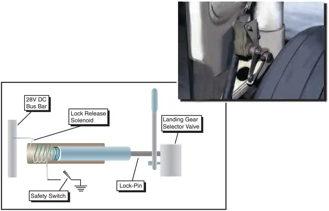
- Electronically operated safety switches prevent accidental operation of the down-locks and inadvertent landing gear retraction while the airplane is on the ground
- A landing gear safety switch, sometimes referred to as a squat switch, is usually mounted in a bracket on one of the main gear shock struts []
- When the weight of the airplane compresses the strut, the switch opens the electrical circuit to the motor or mechanism that powers retraction
- In this way, if the landing gear switch in the cockpit is placed in the RETRACT position when weight is on the gear, the gear will remain extended, and the warning horn may sound as an alert to the unsafe condition
- Once the weight is off the gear, however, such as on takeoff, the safety switch will release, and the gear will retract
- Many airplanes are equipped with additional safety devices to prevent a collapse of the gear when the airplane is on the ground
- These devices are called ground locks
- One common type is a pin installed in aligned holes drilled in two or more units of the landing gear support structure
- Another type is a spring-loaded clip designed to fit around and hold two or more units of the support structure together
- All types of ground locks usually have red streamers permanently attached to them to indicate installation
-
Emergency Gear Extension Systems:
- The emergency extension system lowers the landing gear if the main power system fails
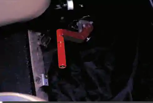
- Some airplanes have an emergency release handle in the cockpit, which connects to the gear up locks through a mechanical linkage
- When operating the handle, it releases the up-locks and allows the gears to free fall or extend under their weight []
- Due to the wind stream, airspeed limitations may apply to ensure the gear lock when extended
- The release of the up-lock may be accomplished using compressed gas directed to up-lock release cylinders []
- In some airplanes, design configurations make an emergency extension of the landing gear by gravity and air loads alone impossible or impractical, and so forceful gear extension in an emergency is required
- Some installations allow either hydraulic fluid or compressed gas provide the necessary pressure, while others use a manual system such as a hand crank for emergency gear extension []
- Hydraulic pressure for emergency operation of the landing gear comes from an auxiliary hand pump, an accumulator, or an electrically powered hydraulic pump, depending on the design of the airplane
-
Landing Gear Operations:
-
Takeoff and Climb:
- The landing gear should be retracted after lift-off when the airplane has reached an altitude where, in the event of an engine failure or other emergency requiring an aborted takeoff, the aircraft can no longer be landed on the runway
- Landing gear retraction should be pre-planned, taking into account the length of the runway, climb gradient, obstacle clearance requirements, the characteristics of the terrain beyond the departure end of the runway, and the climb characteristics of the particular airplane
- The landing gear should not be retracted until achieving a positive rate of climb
- If the airplane has not attained a positive rate of climb, there is always the chance it may settle back onto the runway with the gear retracted
- This is especially so in cases of premature lift-off
- The pilot should also remember that leaning forward to reach the landing gear selector may result in accidental forward pressure on the yoke, which will cause the airplane to descend
- As the landing gear retracts, airspeed will increase, and the airplane's pitch attitude may change
- The gear will take several seconds to retract, and becoming familiar with the sounds and feel of normal gear retraction so that any abnormal gear operation can be readily discernible
- Sounds and feels associated with gear retraction and locking (and extension and locking) are unique to the specific make and model airplane
- Abnormal landing gear retraction is most often a clear sign that the gear extension cycle will also be abnormal
- If operating in winter conditions, keeping the gear down (or, alternatively, cycling the gear up and down several times) during the climb allows the airflow to fling off snow and slush
- The landing gear should be retracted after lift-off when the airplane has reached an altitude where, in the event of an engine failure or other emergency requiring an aborted takeoff, the aircraft can no longer be landed on the runway
-
Approach and Landing:
-

Airplane Flying Handbook,
Gear Placards - The operating loads placed on the landing gear at higher airspeeds may cause structural damage due to the forces of the airstream
- Limiting speeds (not found on the airspeed indicator), therefore, are established for gear operation to protect the gear components from becoming overstressed during flight
- They are published in the Airplane Flying Manual/Pilot Operating Handbook for the particular airplane and are usually listed on placards in the cockpit []
- The maximum landing extended speed (VLE) is the maximum speed at which the airplane can be flown with the landing gear extended
- The maximum landing gear operating speed (VLO) is the maximum speed at which the landing gear may be operated through its cycle
- Pilots extend the landing gear by placing the gear selector switch in the GEAR DOWN position
- As the landing gear extends, the airspeed will decrease, and the pitch attitude may increase
- During the several seconds it takes for the gear to extend, the pilot should be attentive to any abnormal sounds or feel
- The pilot should confirm that the landing gear has extension and locking by the normal sound and feel of the system operation as well as by the gear position indicators in the cockpit
- The landing gear should be extended by the time the airplane reaches a point on the downwind leg that is opposite the point of the intended landing
- The pilot should establish a standard procedure consisting of a specific position on the downwind leg at which to lower the landing gear
- Operation of an airplane equipped with a retractable landing gear requires the deliberate, careful, and continued use of an appropriate checklist
- When on the downwind leg, the pilot should make it a habit to complete the landing gear checklist for that airplane
- Standardization:
- Supports muscle memory, avoiding forgetting to lower the gear
- Increases the pilot's awareness of the landing gear's status, checking before landing
- Unless acceptable operating practices dictate otherwise, complete the landing roll and clear the runway before operating any levers or switches - especially the flaps - as it allows the pilot to focus attention on the after-landing checklist and identify the proper controls
- This will ensure safety switches are actuated, deactivating the landing gear retract system
-
-
Transition:
- Pilots transitioning to retractable gear airplanes should be aware of some common errors that lead to accidents:
- Forgetting (neglecting) to extend the landing gear
- Inadvertently retraction of the landing gear
- Activating gear but failed to check gear position
- Misuse of the emergency gear system
- Retracting gear prematurely on takeoff
- Extending gear too late
- To minimize the chances of a landing gear-related mishap, pilots should:
- Use an appropriate checklist
- A condensed checklist placard visible to the pilot serves as a reminder and easy reference
- Be familiar with and periodically review the landing gear emergency extension procedures for the particular airplane. Be familiar with the landing gear warning horn and warning light systems for the particular airplane. Use the horn system to cross-check the warning light system when an unsafe condition is noted
- Review the procedure for replacing light bulbs in the landing gear warning light displays for the particular airplane so that you can properly replace a bulb to determine if the bulb(s) in the display is good. Check to see if spare bulbs are available in the airplane spare bulb supply as part of the preflight inspection
- Be familiar with and aware of the sounds and feel of a properly operating landing gear system
- Use an appropriate checklist
- Pilots transitioning to retractable gear airplanes should be aware of some common errors that lead to accidents:
-


Aircraft Landing Gear Components and Equipment
- There are varying different parts, linkages, and hoses that are necessary for landing gear to provide their function, including:
- Struts
-
Struts:
- Struts transmit shock loads of landing, takeoff, and taxi to the airplane structure
- There are three types of landing gear struts:
- Bungee
- Spring
- Oleo
-
Bungee Struts:
- Bungee struts slowly distribute forces to the airframe at acceptable rates to reduce any bouncing tendencies
-
Spring Struts:
- Bungee struts slowly distribute forces to the airframe at acceptable rates to reduce any bouncing tendencies
-
Oleo Struts:
- Oleo struts are composed of oil and air (typically nitrogen)
- A piston absorbs the shock during operations
- Oil absorbs landing shocks
- Air absorbs taxi shocks
-
Steering Linkages:
- Steering is typically controlled through the rudder pedals, but in larger aircraft, separate controls are used
- A steerable nosewheel or tailwheel permits the airplane to be controlled throughout all operations while on the ground
- Steerable wheels are linked to the rudders by cables or rods, while caster wheels are free to swivel
- In both cases, the aircraft is steered using the rudder pedals
- Aircraft with castering wheels may require the pilot to combine the use of the rudder pedals with the independent use of the brakes
-
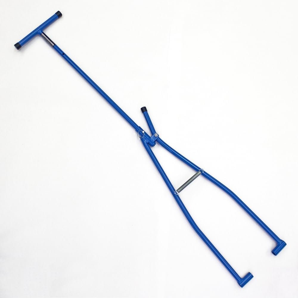
Tow Bars:
- Tow bars attach to the aircraft to better steer the aircraft during ground tows []
- Tow bars range from bars you drag to drill-powered and even remote tug devices
- As simple as they may seem, take the time to learn how to tow an aircraft before attempting
- It is critical to remember/add to checklists to remove the tow bar prior to takeoff!
- Failure to do so may result in damage to the aircraft or worse.
- The towbar should never be attached to the plane unless the pilot is attached to the towbar
- It is best practice to:
- Illuminate aircraft lights when towing, even if during the day
- Inspect the wheels for any damage and ensure the parking brake is off
- Utilize wing walkers when towing in the vicinity of other objects
Aircraft Brakes
- Brakes are necessary to slow the aircraft down after touchdown on the runway to a speed at which they can turn onto a taxiway
- In the case of most modern airplanes, airplane brakes are generally disc brakes
- They consist of multiple (one for each pedal) hydraulically actuated pads (called caliper pads) squeezed toward each other with a rotating disk (called a rotor) between them
- The pads place pressure on the rotor, which is turning with the wheels
- As a result of the increased friction on the rotor, the wheels inherently slow down and stop turning
- The disks and brake pads are made either from steel, like those in a car, or from a carbon material that weighs less and can absorb more energy
- Because airplane brakes are used principally during landings and must absorb enormous amounts of energy, their life is measured in landings rather than miles
- Typically located on the main gear only
- Applied by either a hand control or by foot pedals (toe or heel).
- Foot pedals operate independently, allowing for differential braking, and can supplement nosewheel/tailwheel steering for ground operations.
- Disc brakes are most common on trainers
- Most brake systems are hydraulically actuated
- Air brakes may be used to slow the aircraft for landing and while in flight
- Breaks controlled by the top of the rudder pedal to apply pressure
- When pressure is applied, fluid from the reservoir is directed via the master cylinder to the calipers
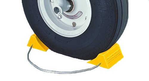
- A parking brake helps keep the brake applied during ramp operations, as do aircraft chocks []
Aircraft Landing Gear and Tire Servicing and Maintenance
-
Tire Pressure:
- Service tires with an air compressor or nitrogen for almost every general aviation aircraft
- Commercial aircraft require nitrogen to compensate for lower temperatures at altitude, increasing tire pressure stability and overall physical integrity
- Tire pressure changes by about 1 psi per 10° F (pressure increases with increased temperature, and vice versa)
- Improperly inflated tires will not only result in undesirable performance but also increased wear
- Underinflated tires can lead to reduced braking performance, increased wear, or tire damage (excessive wear, ply separation, blowout)
- Overinflation can make tires susceptible to damage and reduce traction, ride quality, or tire damage (bursts)
- Tire pressure should be checked daily
- If recently installed, tire pressure may vary as initial inflation may stretch the material
- Service tires with an air compressor or nitrogen for almost every general aviation aircraft
-
Wheel Hardware:
- The hub and bearing bore are susceptible to corrision if left unmaintained
- The hub bearings specifically must remain greased (not oiled) to minimize friction and resist moisture
- Untreated bearings will lead to corrision on the wheel halves
-
Breaks & Brake Assemblies:
- Brake fluid is hydroscopic, meaning the fluid can absorb and retain moisture
- Moisture, typically entered through the vented reservoir, can accumulate in the lower portions of the system, causing corrision
- The lowest part of the system is typically a caliper
- Bleeding the brakes avoids moisture buildup; however, note that bleeding is not considered preventative maintenance and requires an A&P
-
Tire Surface Condition:
- Landing in crosswinds increases the risk of flat spots, reducing the life of tires
- Cracks in the sidewall are unacceptable
- Cracks on the tread are acceptable until they interfere with the tread
-
Tire Storage:
- Reduce, where possible, sun exposure to tires, as ultraviolet light will break down rubber over time
- Low-wing aircraft will have less of a problem with UV light than high-wing
- Reduce, where possible, sun exposure to tires, as ultraviolet light will break down rubber over time
Aircraft Landing Gear Malfunctions
- Treat any indication of a malfunction as actual
- The pilot should not recycle the landing gear if indications or sounds suggest an irregularity
- Consider landing at an airfield with Crash Fire Rescue
- Before landing, exhaust all avenues for correcting the problem (maintenance, ATC, any other instructors)
- Consider exhausting all fuel possible to reduce the risk of fire
- After landing, remain on the runway and contact the maintenance department to inspect the gear before it is taxied or towed back to the ramp
-
Landing Gear Fails to Retract:
- When the landing gear will not retract after takeoff, the pilot should leave the landing gear extended
- Trying to force the landing gear to retract may cause the landing gear to become stuck in the retracted position
- Landing gear position may be confirmed by the tower or other aircraft
- If the landing gear appears locked down, then flight may be continued at reduced performance
- Consideration should be given to rescue services at the destination in the event of further emergency
- Consideration should be given to inspecting the landing gear before taxiing, following landing
- When the landing gear will not retract after takeoff, the pilot should leave the landing gear extended
-
Landing Gear Fails to Extend:
- When the landing gear will not extend, the pilot should try to manually extend the landing gear
- Landing gear position may be confirmed by the tower or other aircraft
- If a gear-up landing is required, consideration should be given to pavement vs. grass to ensure a smoother landing (no bumps, etc.
- Consideration should also be given to fields with the appropriate services desired after an emergency landing
-
Parking Brake Fails to Disengage:
- If the parking brake fails to disengage in a tricycle gear aircraft, more than likely, the aircraft won't move or it will try to rotate about the stuck wheel
- The risk to the aircraft is relatively minimal, of course, unless there are objects very nearby
- Tail dragger airplanes risk a prop strike if attempted to move, as the aircraft will immediately rotate forward
- If the parking brake fails to disengage in a tricycle gear aircraft, more than likely, the aircraft won't move or it will try to rotate about the stuck wheel
-
Shimmy Damper Failure:
- Dampener shimmy will be felt in the rudder pedals when malfunctioning
-
Blown Tire:
- A blown tire will produce a turning moment toward the blown tire when on the surface
- Pilots should be suspicious of other damage that could have occurred when the wheel blew, especially when operating retractable landing gear
Common Training Aircraft Landing Gear Characteristics
-
Cessna-172:
- Tricycle type w/ steerable nose wheel
- Shock absorption is provided by tubular spring steel main landing gear struts and the air/oil nosegear shock strut
- Each main gear is equipped with a hydraulically actuated disc-type brake on the inboard side of each wheel
- Each brake is connected by hydraulic lines to a master cylinder, which is attached to each of the pilot's rudder pedals
- Effective steering is accomplished through nosewheel steering by using the rudder pedals (ground)
- The nosewheel turns about 10° on each side of center
- Applying left or right brake results in differential braking
- The minimum turning radius using differential brakes is about 27 feet
-
Piper Arrow:
- Retractable tricycle landing gear
- Hydraulically actuated by an electrically powered reversible pump
- The operation takes about 7 seconds
- Has emergency gear extension lever to equalize system pressure
- The nosewheel is spring-assisted during freefall
- Nose gear steerable 30° arc on each side of center
- WARNING GEAR UNSAFE displays when:
- Gear up and power reduced below approximately 14" manifold pressure,
- Gear selector UP on the ground with the throttle in retarded position, or
- Flaps extended beyond 10° without gear down and locked
- Warning horn sounds at 90 Hz
- The main gear uses Cleveland single-disc hydraulic breaks
- Toe breaks and the parking brake use separate cylinders, but a common reservoir
Aircraft Landing Gear Knowledge Check


Aircraft landing Gear Conclusion
- Follow established procedures and practice to avoid distractions, which can lead to landing with the gear up
- Depending on the type of landing gear, an understanding of the aircraft's electrical and/or hydraulics & pneumatic systems is required
- Landing gear may also be used to increase rates of descent by increasing drag
- Learn more about tire maintenance and operational practices with Advisory Circular (20-97) Aircraft Tire Maintenance and Operational Practices.
- Sometimes, with landing gear, less is more
- Aerodynamic breaking, that is, the raising of flaps, trying to hold the nose up, are effective ways to slow the aircraft before the pilot must apply brakes
- Still looking for something? Continue searching:
Aircraft landing Gear References
- Advisory Circular (20-97) Aircraft Tire Maintenance and Operational Practices.
- Airplane Flying Handbook (11-9) Retractable Landing Gear.
- Airworthiness Directive (87-08-09) Tire Inflation.
- Aircraft Owners and Pilots Association - Time to Change Those Tires.
- Federal Aviation Administration - Pilot/Controller Glossary.
- Pilot Handbook of Aeronautical Knowledge (6-32) Brakes.
- Pilot Handbook of Aeronautical Knowledge (6-31) Landing Gear.
- Reddit - PSA: Did you remove your towbar!?.