Powerplant
The aircraft powerplant (engine) provides mechanical force to power the aircraft and associated accessories necessary for flight.
Introduction to Powerplant
- The aircraft powerplant (engine) provides mechanical force to power the aircraft and associated accessories necessary for flight
- Almost every system on the aircraft is run from or in conjunction with the engine
- The most common powerplant among general aviation is the reciprocating engine.
- With the ignition and induction sub-systems
- Reciprocating engines performance limitations can be increased through the installation and use of turbo/superchargers.
- More advanced aircraft utilize gas-turbine engines.
- Although turbine engines share some operating characteristics with reciprocating engines, they are constructed differently, requiring different instrumentation and operating characteristics.
- Although not wholey unique, foreign object debris is one of those considerations
- Finally, with such a complex and critical system, malfunctions & emergencies are possible, and require pilot action
- The type of engine is a deliberate choice in design, based on the desired performance.
- Engines can be placed on the front (typical) or back (atypical) of an aircraft and are encased in a cover called a cowling, which direct airflow an assist powerplant cooling systems.
Powerplant Key Highlights
- Aircraft powerplants produce the thrust or power necessary to propel aircraft during flight operations.
- Common aircraft powerplants include reciprocating engines, turbine engines, turboprops, turbojets, and turbofan engines.
- Powerplants convert fuel energy into mechanical or jet thrust energy through controlled combustion processes.
- Engine performance depends on factors such as altitude, temperature, fuel quality, airflow, and power management techniques.
- Aircraft powerplants rely on integrated systems including fuel, ignition, lubrication, induction, cooling, and exhaust systems.
- Pilots should monitor engine instruments carefully to identify abnormal temperatures, pressures, vibrations, or performance indications.
- Improper engine operation or system malfunctions can lead to power loss, overheating, or engine failure.
- Regular maintenance and inspection procedures help ensure powerplant reliability and operational safety.
- Modern aircraft engines may incorporate electronic engine controls and advanced monitoring systems to improve efficiency and performance.
- Understanding aircraft powerplants improves systems knowledge, engine management proficiency, and overall flight safety.
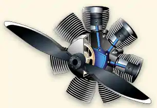
Reciprocating Engines
- Reciprocating, also known as piston, engines are the primary powerplant in use for general aviation.
- A rotating motion is created by converting chemical energy to mechanical via the combustion cycle.
- The chemical energy can be fuel or with advances in technology, a hybrid or, entirely electric.
- The mechanical energy is translated to the propeller via reciprocating pistons.
- Engines may be mounted on the firewall (single-engine) or wings (multi-engine), but in all cases, are separate from the aircraft cabin.
-
Types of Reciprocating Engines:
- Engine design reflects the desired performance, balanced with tradeoffs and include:
-
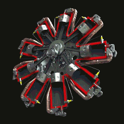
Radial Engines:
- Radial engines consists of a row or rows of cylinders arranged in a circular pattern around the crankcase. []
- Radial engines were once popular for their high power-to-weight ratio and large frontal area that provided even cooling; however, as technology has advanced, liquid cooling has become the standard for several reasons.
- The Douglas DC-3 is one such example of radial engine use.
-
In-Line Engines:
- In-line engines have a small frontal area but low power-to-weight
- Cooling is difficult as the rear cylinders don't receive much air, limiting to a four or six cylinder configuration
-
V-Type Engines:
- A fairly common variation of the in-line engine is the V-Type.
- V-Type engines combine the benefit of small frontal areas while providing better power-to-weight ratios and cooling.
- A notable example of the V-Type design is the North Amercian P-51 Mustang.
-
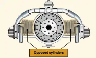
Horizontally-Opposed Engines:
- Most popular, used on smaller aircraft []
- Horizontally-opposed engines always have an even number of cylinders (for opposition)
- They are relatively small and light-weight giving a higher power-to-weight ratio
- Reduced frontal area reduces aerodynamic drag
- The horizontally-opposed engine is in common use with many general aviation aircraft including the Cessna 172.
-
Rotary Engines:
- Rotary engines use a three-sided "piston" to accomplish the motion
- These engines will have an odd number of cylinders
- These are highly reliable engines and favorable power-to-weight ratio
- Limited to small engine applications
- Reciprocating engines may be classified by:
- Operating cycle (two or four)
- Method of cooling (liquid or air)
- Cylinder arrangement relative to the crankshaft (radial, in-line, v-type, or opposed)
-
Reciprocating Engine Instrumentation:
- Reciprocating engines are monitored and managed by the pilot through the use of various types of engine instrumentation
-
Oil Pressure Gauge:
- Measures the oil pressure within the engine
-
Oil Temperature Gauge:
- Measures the oil temperature within the engine
- Reduced oil quantity, airflow, or an excessively lean mixture will cause the oil temperature to rise
- Conversely, the opposite will cause the temperature to decrease
-
Engine Temperature Gauge:
- Measures the temperature of the engine's cylinder head temperature, or CHT
-
Tachometer:
- The tachometer, sometimes called "tach" measures engine RPM
- This means the tachometer time moves slower at low RPM and faster at higher RPM
- Operating characteristics such as expected performance is found in either the Pilot Operating Handbook or Type Certificate Data Sheet
- "Tach time" is generally the way maintainers will measure 100-hour inspections.
- The tachometer, sometimes called "tach" measures engine RPM
-
Hobbs Meter:
- Although not exactly an engine instrument, the Hobbs meter runs when the engine turns on until it turns off, utilizng an oil pressure switch
- This records the time the engine is running
- Although not exactly an engine instrument, the Hobbs meter runs when the engine turns on until it turns off, utilizng an oil pressure switch
-
Manifold Pressure Gauge:
- On aircraft with a constant speed propeller, RPM is an inefficient way to measure engine power, and therefore, a manifold pressure guage is necessary
- The manifold pressure indicates the vacuum inside of the intake (manifold)
- Said differently, it is measuring the volume of air passing from the intake, through the manifold, and ultimately to the engine
- Manifold pressure is typically measured between the throttle body and the cylinders
- With the engine off, the manifold pressure will read as ambient
- As the aircraft's altitude increases, the pressure indicated on a non-turbocharged aircraft will show a decrease of 1 inch for every 1,000 ft, assuming the standard lapse rate
- All other things constant, the more the throttle is advanced, the more fuel is required, therefore the more air is required and manifold pressure rises
- As the engine spins faster the propeller's RPM must be adjusted to keep manifold pressure within limits
Reciprocating Engine Ignition System
- The ignition system provides the spark to ignite the mixture in the cylinders
- In piston engines, the ignition system consists of magnetos, spark plugs, wires, and an ignition switch
- Turbine aircraft ignitions systems are set up differently, detailed below
- Together, the ignition system provides either spark or compression ignition
-
Magnetos:
- Magnetos are self-contained engine-driven units to supply electrical current to the spark plugs
- Most airplanes have a dual ignition system (two individual magnetos, separate wires, separate plugs, and other components to increase reliability)
- If one magneto or spark plug fails, the other is unaffected and will continue to run normally, with a slight decrease in power
- The ignition switch controls the magnetos operation
- Magneto checks are performed before takeoff to ensure the grounding wires are grounded
-
Magneto Checks:
- Magneto checks test the ignition system's operation and are a critical element to ground checklists
- When checking magnetos there a few conditions must be satisfied to ensure proper functionality:
- The magneto grounding wires are connected
- If not connected, there will be no drop in RPM when that magneto is selected
- The drop in RPM falls within the recommended limits as defined in the Pilot Operating Handbook
- A drop, but continued operation of the engine, ensures the aircraft can fly on a single magneto, albiet at reduced performance
- The differential drop between magnetos is within limits as defined in the Pilot Operating Handbook
- Excessive differentials demonstrate a malfunction in one of the magnetos
- If the drop is greater than the recommended limits as defined in the Pilot Operating Handbook
- Consider running the engine to a cruise/near-cruise RPM and leaning to peak EGT
- Run lean of peak at high RPM for about 30 seconds
- If magneto checks after a second or even third time, have the engine looked at by a mechanic
- If equipped, pilots should also monitor EGT for a rise on all cylinders
- Note that when checking EGT, a drop in a single cylinder's EGT is one way to identify the malfunctioning magneto
- No drop indicates there is a break in the grounding wire, and they will remain hot even when they are supposed to be off
- If not grounded magnetos may fire while "OFF," if the propeller rotates
- Any fuel that remains in the cylinders could ignite if the magnetos fire, causing serious injury to anyone around the propeller
- If not grounded magnetos may fire while "OFF," if the propeller rotates
- The magneto grounding wires are connected
- Although magneto checks are normally performed on the ground, they may also be performed in flight.
- Note that aging magnetos can manifest themselves and provide a warning through hot starts, before ever performing the magneto check
- Magneto checks are usually performed before takeoff to:
- Allow the aircraft to warm up
- Check condition prior to takeoff (taxi may foul)
- Avoid propwash concerns in the ramp area
- The ignition switch is moved from BOTH to "R" (right) and "L" (left) to ensure a drop in Rotations Per Minute (RPM) occurs
- Moving the ignition switch to "R" means you're running on the right magneto
- Moving the ignition switch to "L" means you're running on the left magneto
- Mechanically, it doesn't matter which side is checked first
- Checking the right magneto (two clicks to left) first means when checking the left second (one click to the left), it is less likely to accidentally select the left (not BOTH) magnetos following the check, often before takeoff
-
Starter Generators:
-
Abnormal Combustion:
- Normal combustion is smooth and constant
- Detonation - explosive ignition caused by excessive temperatures and pressure, which can lead to engine damage or using a lower than recommended fuel grade
- Causes overheating, engine roughness, and/or loss of power
- Detonation can lead to pre-ignition
- Pre-ignition is when the mixture ignites in advance of the normal timed ignition
- Hot spots, such as carbon deposits, are the leading cause of pre-ignition
- The two occur simultaneously with the same effects, so it's hard to detect which is happening, reducing engine temperatures should solve the problem
-
Spark-Ignition:
[]- Highly reliable
- Operates on the principle of magnetos and spark plugs, similar to a car
- Uses a spark plug to ignite a pre-mixed fuel/air mixture ("weight of fuel to the weight of air")
-
Compression-Ignition:
- Reduces operating cost, simplifies design, improved reliability
- Often referred to as jet fuel piston engines as they utilize lower-cost diesel or jet fuel which is more readily available
- Compresses air in the cylinder, raising its temperature to a degree necessary for automatic ignition when injectiong fuel into the cylinder
- Both use cylindrical compression chambers and pistons that convert linear motion into the rotary motion of the crankshaft and, therefore, the propeller
-
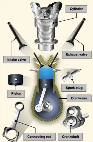
Combustion Cycle:
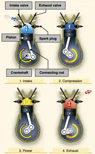
- The combustion cycle consists of four phases, intake, compression, power, and exhaust
- The cycle can be remembered using the common saying of "suck, squeeze, bang, blow"
-
Intake:
- The intake stroke begins as the piston starts its downward travel
- When this happens, the intake valve opens, and the fuel/air mixture flows into the cylinder
-
Compression:
- Compression begins when the intake valve closes and the piston starts moving back to the top of the cylinder
- This phase of the cycle enables a much greater power output from the fuel/air mixture upon ignition
-
Power:
- The power phase begins when the fuel/air mixture is ignited
- Ignition causes a tremendous pressure increase in the cylinder and forces the piston downward away from the cylinder head, creating the power that turns the crankshaft
-
Exhaust:
- Used to purge the cylinder of burned gases
- Exhaust begins when the exhaust valve opens and the piston starts to move toward the cylinder head once again
- Continuous operation is dependent on the auxiliary functions listed at the top of this page
-
Four-Stroke Engines:
- Conversion of chemical energy occurs over a four-stroke operating cycle []
-
Components:
-
Cylinders
- Exhaust valves
- Spark plugs
- Pistons
-
Crankcase
-
Accessories
- Magnetos
-
- Each step, Intake, Compression, Power, and Exhaust happen in four individual strokes
- Each cylinder is operating on a different stroke
- Even when at a low speed, this cycle occurs several hundred times per minute
-
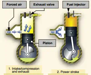
Two-Stroke Engines:
- Conversion of chemical energy occurs over a two-stroke operating cycle []
- Intake compression power and exhaust occurs in only two-strokes of the piston
- Will produce more power per stroke and thereby increase its power-to-weight ratio
- Due to inefficiencies of design and emission, these engines have been limited and typically only find use in aviation
- Through modern technology, most of these shortfalls have been mitigated, however, the four-stroke remains the most common design
Induction Systems
- Induction systems control the fuel/air ratio and its delivery to cylinders
- Mixture levers control the fuel/air ratio
- Throttle levers control the amount of mixture to the engine
- The intake port takes in outside air through a filter
- In case of a blockage, an alternate source is drawn from inside the cowling, bypassing the filter
- Further details are described on the induction systems page
-
Induction Accessories:
- These systems compress the intake air to increase its density to increase horsepower
- The key difference between the two lies in the power supply:
- A supercharger relies on an engine-driven RPM or compressor, reducing engine power.
- A turbocharger (originally known as a turbo-supercharger) gets its power from the exhaust stream that runs through a turbine, which in turn spins the compressor, saving engine power but reducing throttle responses.
- Aircraft with these systems have a manifold pressure gauge, which displays Manifold Pressure (MAP) within the engine's intake manifold
- As a normally aspirated aircraft climbs, it eventually reaches an altitude where the MAP is insufficient for a normal climb
- That altitude limit is the aircraft's service ceiling, and it is directly affected by the engine's ability to produce power
- If the induction air entering the engine is pressurized or boosted, by either a supercharger or a turbocharger, the aircraft's service ceiling can be increased
- With these systems, an aircraft can fly at higher altitudes with the advantage of higher true airspeeds and the increased ability to circumnavigate adverse weather
- The most efficient method of increasing horsepower in an engine is by use of a supercharger or turbocharger
- When turbo/superchargers are installed on an engine, the booster uses the engine's exhaust gases to drive an air compressor to increase the pressure of the air going into the engine through the carburetor or fuel injection system to boost power at a higher altitude
- The major disadvantage of the gear-driven supercharger-use of a large amount of the engine's power output for the amount of power increase produced-is avoided with a turbocharger, because an engine's exhaust gases power turbochargers
- This means a turbocharger recovers energy from hot exhaust gases that would otherwise be lost
- The second advantage of turbochargers over superchargers is the ability to maintain control over an engine's rated sea level horsepower from sea level up to the engine's critical altitude
- Critical altitude is the maximum altitude at which a turbocharged engine can produce its rated horsepower
- Above the critical altitude, power output begins to decrease, like it does for a normally aspirated engine
- Two main elements comprise a turbocharger:
- A compressor, and;
- A Turbine
- The compressor section houses an impeller that turns at a high rate of speed
- As induction draws air across the impeller blades, the impeller accelerates the air, allowing a large volume of air into the compressor housing
- The impeller's action subsequently produces high-pressure, high-density air for delivery to the engine
- The engine's exhaust gases drive a turbine wheel that is mounted on the opposite end of the impeller's drive shaft, thereby driving the impeller
- By directing different amounts of exhaust gases to flow over the turbine, more energy is extracted, causing the impeller to deliver more compressed air to the engine
- The wastegate, essentially an adjustable butterfly valve installed in the exhaust system, is used to vary the mass of exhaust gas flowing into the turbine
- When closed, most of the exhaust gases from the engine flow through the turbine
- When open, the exhaust gases are allowed to bypass the turbine by flowing directly out through the engine's exhaust pipe
- Since the temperature of a gas rises when compressed, turbocharging causes the temperature of the induction air to increase
- Many turbocharged engines use an intercooler to reduce temperatures and lower the risk of detonation
- This small heat exchanger uses outside air to cool the hot compressed air before it enters the fuel metering device
Turbo/Superchargers
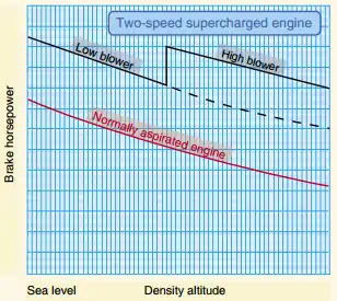
- In a normally aspirated engine, the amount of power is limited by the air pressure (less air pressure at altitude = less fuel = less power)
- Power loss is approximately 1 inch per every thousand feed
- The turbocharged engine allows the pilot to maintain sufficient cruise power at high altitudes where there is less drag, which means faster true airspeeds and increased range with fuel economy []
- At the same time, the powerplant has the flexibility to fly at a low altitude without the increased fuel consumption of a turbine engine
- When attached to the standard powerplant, the turbocharger does not take any horsepower from the powerplant to operate; it is relatively simple mechanically, and some models can pressurize the cabin as well
- The turbocharger is an exhaust-driven device, which raises the pressure and density of the induction air delivered to the engine ("altitude engine")
- It consists of two separate components: a compressor and a turbine connected by a common shaft
- The compressor supplies pressurized air to the engine for high altitude operation
- The compressor and its housing are between the ambient air intake and the induction air manifold
- The turbine and its housing are part of the exhaust system and utilize the flow of exhaust gases to drive the compressor
- The turbine has the capability of producing manifold pressure greater than the maximum allowable for the particular engine
- To not exceed the maximum allowable manifold pressure, a bypass or wastegate is installed, diverting some exhaust overboard before it passes through the turbine
- The position of the wastegate regulates the output of the turbine and, therefore, the compressed air available to the engine
- When the wastegate is closed, all of the exhaust gases pass through and drive the turbine
- As the wastegate opens, some exhaust gases are routed around the turbine, through the exhaust bypass and overboard through the exhaust pipe
- The wastegate actuator is a spring-loaded piston operated by engine oil pressure
- The actuator, which adjusts the wastegate position, is connected to the wastegate by a mechanical linkage
- The control center of the turbocharger system is the pressure controller
- This device simplifies turbo-charging to one control: the throttle
- Once the pilot has set the desired manifold pressure, virtually no throttle adjustment is required with changes in altitude
- The controller senses compressor discharge requirements for various altitudes and controls the oil pressure to the wastegate actuator, which adjusts the wastegate accordingly
- Thus the turbocharger maintains only the manifold pressure called for by the throttle setting
-
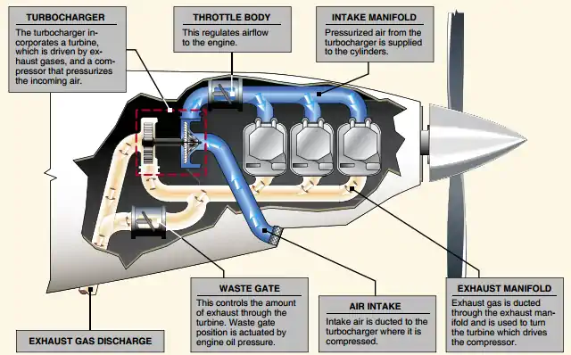
Pilot Handbook of Aeronautical Knowledge, Turbocharger Components -
High-Altitude Performance:
- As an aircraft equipped with a turbocharging system climbs, the wastegate is gradually closed to maintain the maximum allowable manifold pressure
- At some point, the wastegate will be fully closed, and further increases in altitude will cause the manifold pressure to decrease
- This is the critical altitude, which is established by the aircraft or engine manufacturer
- When evaluating the performance of the turbocharging system, be aware that if the manifold pressure begins decreasing before the specified critical altitude, the engine and turbocharging system a qualified aviation maintenance technician must inspect and verify the system's proper operation
-
Ground Boosting vs. Altitude TurboCharging:
- Altitude turbocharging (sometimes called "normalizing") uses a turbocharger that will maintain maximum allowable sea-level manifold pressure (normally 29 - 30 inches Hg) up to a certain altitude
- This airplane manufacturer specified altitude is the airplane's critical altitude
- Above the critical altitude, the manifold pressure decreases with an increase in altitude
- Ground boosting, on the other hand, is an application of turbocharging that uses more than the standard 29 inches of manifold pressure in flight
- In various airplanes using ground boosting, takeoff manifold pressures may go as high as 45 inches of mercury
- Although a sea-level power setting and maximum RPM can be maintained up to the critical altitude, this does not mean that the engine is developing sea-level power
- Engine power is not determined just by manifold pressure and RPM Induction air temperature is also a factor
- Turbocharged induction air heats as a result of compression. This temperature rise decreases induction air density which causes a power loss
- Maintaining the equivalent horsepower output will require a somewhat higher manifold pressure at a given altitude than if the induction air were not compressed by turbocharging
- If, on the other hand, the system incorporates an automatic density controller which, instead of maintaining a constant manifold pressure, automatically positions the wastegate to maintain constant air density to the engine, a near-constant horsepower output will result
- Altitude turbocharging (sometimes called "normalizing") uses a turbocharger that will maintain maximum allowable sea-level manifold pressure (normally 29 - 30 inches Hg) up to a certain altitude
-
Superchargers:
- A supercharger is an engine-driven or compressor that provides compressed air to the engine to provide additional pressure to the induction air so the engine can produce additional power
- It increases manifold pressure and forces the fuel/air mixture into the cylinders
- The higher the manifold pressure, the more dense the fuel/air mixture, and the more power an engine can produce
- With a normally aspirated engine, it is not possible to have manifold pressure higher than the existing atmospheric pressure
- A supercharger is capable of boosting manifold pressure above 30 inHg
- Example:
- At 8,000', a typical engine may be able to produce 75% of the power it could produce at Mean Sea Level (MSL) because the air is less dense at the higher altitude
- The supercharger compresses the air to a higher density allowing a supercharged engine to produce the same manifold pressure at higher altitudes as it could produce at sea level, increasing its service ceiling []
- Thus, an engine at 8,000' MSL could still produce 25 inHg of manifold pressure, whereas without a supercharger it could produce only 22 inHg
- With a normally aspirated engine, it is not possible to have manifold pressure higher than the existing atmospheric pressure
- A supercharger is capable of boosting manifold pressure above 30 inHg
- Critical altitude is the altitude where you can no longer maintain a constant manifold pressure
- Components:
- Superchargers generally mount between the fuel metering device and intake manifold
- The engine drives a supercharger through a gear train at one speed, two speeds, or variable speeds
- Superchargers can have one or more stages
- Each stage also provides an increase in pressure, and superchargers may classify as single-stage, two-stage, or multistage, depending on the number of times compression occurs
- An early version of a single-stage, single-speed supercharger may be referred to as a sea-level supercharger
- An engine equipped with this type of supercharger is called a sea-level engine
- With this type of supercharger, a single gear-driven impeller increases the power produced by an engine at all altitudes
- The drawback with this type of supercharger is a decrease in engine power output with an increase in altitude
- Single-stage, single-speed superchargers are found on many high-powered radial engines and use an air intake that faces forward so the induction system can take full advantage of the ram air
- Intake air passes through ducts to a carburetor, where fuel meters in proportion to the airflow
- Next, the fuel/air charge is ducted to the supercharger, or blower impeller, which accelerates the fuel/air mixture outward
- Once accelerated, the fuel/air mixture passes through a diffuser, where air velocity becomes pressure energy (velocity decreases as pressure increases)
- After compression, the resulting high-pressure fuel/air mixture is directed to the cylinders
- Some of the large radial engines developed during World War II have a single-stage, two-speed supercharger
- With this type of supercharger, a single impeller may operate at two speeds
- The low impeller speed is often referred to as the low blower setting, while the high impeller speed is called the high blower setting
- On engines equipped with a two-speed supercharger, a lever or switch in the flight deck activates an oil-operated clutch that switches from one speed to the other
- Under normal operations, takeoff the supercharger is left in the low blower position
- In this mode, the engine performs as a ground-boosted engine, and the power output decreases as the aircraft gains altitude
- However, once the aircraft reaches a specified altitude, a power reduction is made, and the pilot switches the supercharger control to the high blower position
- The throttle is then reset to the desired manifold pressure
- An engine equipped with this type of supercharger is called an altitude engine []
-
Turbo/Supercharger System Failures:
- Because of the high temperatures and pressures produced in the turbine exhaust systems, turbocharger malfunctions require extreme caution
- In all cases of turbocharger operation, follow the manufacturer's recommended procedures
- In those instances where the manufacturer's procedures do not adequately describe the actions to be taken in the event of a turbocharger failure, consider the following
-
Waste Gate Failure:
- Improper regulation of speeds
-
Over-Boost Condition:
- With air being pumped into the cylinders under pressure by the turbocharger and then further compressed by the piston, there is more danger of detonation (knock)
- Knocking happens because as you compress air, the temperature of the air increases
- The temperature may increase enough to ignite the fuel before the spark plug fires
- If an excessive rise in manifold pressure occurs during normal advancement of the throttle (possibly due to faulty operation of the wastegate):
- Immediately retard the throttle smoothly to limit the manifold pressure below the maximum for the RPM and mixture setting
- Operate the engine in such a manner as to avoid a further over-boost condition
- If the boost pressure is really high, the compression ratio of the engine may have to be reduced or octane increased to avoid knocking
-
Low Manifold Pressure:
- Although this condition may be caused by a minor fault, it is quite possible that a serious exhaust leak has occurred creating a potentially hazardous situation:
- Shut down the engine in accordance with the recommended engine failure procedures, unless a greater emergency exists that warrants continued engine operation
- If continuing to operate the engine, use the lowest power setting demanded by the situation and land as soon as practicable
- It is very important that corrective maintenance occur following any turbocharger malfunction
- Although this condition may be caused by a minor fault, it is quite possible that a serious exhaust leak has occurred creating a potentially hazardous situation:
- Because of the high temperatures and pressures produced in the turbine exhaust systems, turbocharger malfunctions require extreme caution
-
System Operation:
- On most modern turbocharged engines, a pressure-sensing control mechanism coupled to an actuator governs the position of the wastegate
- Engine oil, directed into or away from this actuator moves the wastegate position
- The actuator is automatically positioned to produce the desired MAP simply by changing the position of the throttle control
- Other turbo-charging system designs use a separate manual control to position the wastegate
- With manual control, the manifold pressure gauge must be closely monitored to achieve the desired MAP
- Manual systems are often on aircraft that have been modified with after-market turbocharging systems and require special operating considerations
- For example, if the wastegate remains closed after descending from a high altitude, it is possible to produce a manifold pressure that exceeds the engine's limitations
- This condition, called an over-boost, may produce severe detonation because of the leaning effect resulting from increased air density during descent
- Although an automatic wastegate system is less likely to experience an over-boost condition, it can still occur
- To help prevent over-boosting, advance the throttle cautiously to prevent exceeding the maximum manifold pressure limits
- For example, a turbocharger turbine and impeller can operate at rotational speeds greater than 80,000 RPM while at extremely high temperatures
- The bearings are constantly supplied with engine oil to reduce the frictional forces and high temperature
- To obtain adequate lubrication, the oil temperature should be in the normal operating range before high throttle settings are applied
- If power is applied while the engine oil temperature is below its normal operating range, the cold oil may not flow out of the wastegate actuator quickly enough to prevent an over-boost
- Also, allow the turbocharger to cool and the turbine to slow down before shutting the engine down
- Otherwise, the oil remaining in the bearing housing will boil, causing hard carbon deposits to form on the bearings and shaft, which deposits rapidly deteriorate the turbocharger's efficiency and service life
- For further limitations, refer to the Airplane Flight Manual (AFM)/Pilot Operating Handbook (POH)
- The pilot should carefully monitor engine indications when making power changes
- Aggressive and/or abrupt throttle movements increase the possibility of over-boosting
- When the wastegate is open, the turbocharged engine will react the same as a normally aspirated engine when the RPM is varied
- That is, when the RPM is increased, the manifold pressure will decrease slightly
- When the engine RPM is decreased, the manifold pressure will increase slightly
- When the wastegate is closed, manifold pressure variation with engine RPM is just the opposite of the normally aspirated engine
- An increase in engine RPM will increase manifold pressure, and a decrease in engine RPM will result in a decrease in manifold pressure
- Above the critical altitude, where the wastegate is closed, any change in airspeed will result in a corresponding change in manifold pressure
- This is true because the increase in ram air pressure with an increase in airspeed is magnified by the compressor increasing manifold pressure
- The increase in manifold pressure creates a higher mass flow through the engine, causing higher turbine speeds and thus further increasing manifold pressure
- When running at high altitudes, aviation gasoline may tend to vaporize before reaching the cylinder
- If this occurs in the portion of the fuel system between the fuel tank and the engine-driven fuel pump, an auxiliary positive pressure pump may be needed in the tank
- Since engine-driven pumps pull fuel, they are easily vapor-locked
- A boost pump provides positive pressure-pushes the fuel-reducing the tendency to vaporize
- Heat Management:
- Turbocharged engines must be thoughtfully and carefully operated, with continuous monitoring of pressures and temperatures
- Two temperatures that are especially important:
- Turbine Inlet Temperature (TIT) or in some installations Exhaust Gas Temperature (EGT)
- Cylinder Head Temperature (CHT)
- TIT or EGT limits protect the elements in the hot section of the turbocharger, while CHT limits protect the engine's internal parts
- Due to the heat of compression of the induction air, a turbocharged engine runs at higher operating temperatures than a non-turbocharged engine
- Because turbocharged engines operate at high altitudes, their environment is less efficient for cooling
- At altitude, the air is less dense and, therefore, cools less efficiently
- Also, the less dense air causes the compressor to work harder
- Compressor turbine speeds can reach 80,000 - 100,000 RPM, adding to the overall engine operating temperatures
- Turbocharged engines are also operated at higher power settings a greater portion of the time
- High heat is detrimental to piston engine operation
- Its cumulative effects can lead to the piston, ring, and cylinder head failure and place thermal stress on other operating components
- Excessive cylinder head temperature can lead to detonation, which in turn can cause catastrophic engine failure
- Turbocharged engines are especially heat sensitive
- The key to turbocharger operation, therefore, is effective heat management
- The pilot monitors the condition of a turbocharged engine with manifold pressure gauge, tachometer, exhaust gas temperature/turbine inlet temperature gauge, and cylinder head temperature
- The pilot manages the "heat system" with the throttle, propeller RPM, mixture, and cowl flaps
- At any given cruise power, the mixture is the most influential control over the exhaust gas/turbine inlet temperature
- The throttle regulates total fuel flow, but the mixture governs the fuel to air ratio
- The mixture, therefore, controls temperature
- Exceeding temperature limits in an after takeoff climb is usually not a problem since a full-rich mixture cools with excess fuel
- At cruise, however, the pilot normally reduces power to 75% or less and simultaneously adjusts the mixture
- Monitor temperature limits closely under cruise conditions because it's there that the temperatures are most likely to reach the maximum, even though the engine is producing less power
- Overheating in an enroute climb, however, may require fully open cowl flaps and a higher airspeed
- Since turbocharged engines operate hotter at altitude than do normally aspirated engines, they are more prone to damage from cooling stress
- Gradual reductions in power and careful monitoring of temperatures are essential in the descent phase
- The pilot may find it helpful to lower the landing gear to give the engine something to work against while power is reduced and provide time for a slow cooldown
- It may also be necessary to lean the mixture slightly to eliminate roughness at the lower power settings
-
Waste Gate Function:
- There are two versions of waste gates used in turbo and superchargers
-
Manually Controlled:
- The pilot controls pressure via a control lever and must remember to open the wastegate before start-up and landing
-
Automatic Control:
- Varies wastegate position to keep a constant pressure at all times until reaching critical altitude, where the wastegate will be fully closed
- On most modern turbocharged engines, a pressure-sensing control mechanism coupled to an actuator governs the position of the wastegate
-
Exhaust System Failuress:
- Exhaust failures:
- Muffler failures/blockages
- Exhaust leaks
- Causing noxious gases or fumes to permeate the cabin
- Exhaust cracks causing heat damage and/or fire
- Exhaust failures:
Gas Turbine Engines
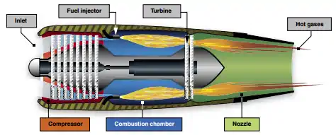
- An aircraft turbine engine consists of an air inlet, compressor, combustion chambers, a turbine section, and exhaust
- Turbine engines produce thrust by increasing the velocity of the air flowing through the engine
- Heat essentially equals thrust; to get more thrust out of an engine, you increase heat
- Turbine engines are highly desirable aircraft powerplants
- They are characterized by smooth operation and a high power-to-weight ratio, and they use readily available jet fuel
- Before recent advances in material, engine design, and manufacturing processes, the use of turbine engines in small/light production aircraft was cost-prohibitive
- Today, several aviation manufacturers are producing or plan to produce small/light turbine-powered aircraft
- These smaller turbine-powered aircraft typically seat between three and seven passengers and are referred to as very light jets (VLJs) or micro-jets
-
Types of Turbine Engines:
- There are four types of aircraft turbine engines:
- Turbojet (pure jet)
- Turbine, propeller combination (Turboprop)
- Turbine engine incorporating a fan (Turbofan)
- Turbine/rotor combination (Turboshaft)
- The path the air takes through the engine and how power is produced determines the type of engine
- Operate off the Brayton Cycle, which is similar to the 4-stroke cycle, except it maintains continuous combustion as all steps occur simultaneously
- Five major components:
- Inlet duct
- Compressor
- Combustion Chamber (or chambers)
- Turbine (or turbines)
- Exhaust assembly
- There are three types of compressors-centrifugal flow, axial flow, and centrifugal-axial flow
- Compression of inlet air in a centrifugal flow engine is accomplished by accelerating air outward perpendicular to the longitudinal axis of the machine
- The axial-flow engine compresses air by a series of rotating and stationary airfoils, moving the air parallel to the longitudinal axis []
- The centrifugal-axial flow design uses both kinds of compressors to achieve the desired compression
- There are four types of aircraft turbine engines:
-
Turbojet:
- Accelerating an airmass through the engine produces thrust
- The turbojet engine consists of four sections: compressor, combustion chamber, turbine section, and exhaust []
- The compressor section passes inlet air at a high rate of speed to the combustion chamber
- A compressor ratio reflects the increase in pressure
- For example, a compression ratio of 10 to 1 means the compressor increases an initial Pounds per Square Inch (PSI), say 15, to 150
- The combustion chamber contains the fuel inlet and igniter for combustion
- The expanding air drives a turbine, which is connected by a shaft to the compressor, sustaining engine operation
- The accelerated exhaust gases from the engine provide thrust
- This is a basic application of compressing air, igniting the fuel-air mixture, producing power to self-sustain the engine operation, and exhaust for propulsion
- Turbojet engines are limited in range and endurance
- They are also slow to respond to throttle applications at slow compressor speeds
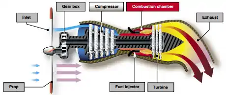
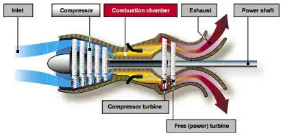
Turboprop:
- Developed to provide the power requirements for aircraft of greater size
- Turboprop engines are capable of developing 2/12 horsepower per pound of weight
- A turboprop engine is a turbine engine that converts most gas energy into mechanical power, which drives a propeller through a reduction gear []
- The exhaust gases drive a power turbine connected by a shaft that drives the reduction gear assembly
- Reduction gearbox converts high RPM, low torque to low RPM, high torque to prevent blade tips from reaching sonic flow
- Reduction gearing is necessary because optimum propeller performance is at much slower speeds than the engine' operating RPM
- Turboprop engines are a compromise between turbojet engines and reciprocating powerplants
- Turboprops, generally speaking, are limited at altitude by temps, limited at low altitude by torque
- Turboprop engines are most efficient at speeds between 250 and 400 Miles Per Hour (MPH) and altitudes between 18,000 and 30,000'
- They also perform well at the slow airspeeds required for takeoff and landing and are fuel-efficient
- The minimum specific fuel consumption of the turboprop engine is normally available in the altitude range of 25,000' to the tropopause
-
Turboprop Assemblies:
-
Power Assembly:
- It consists of the basic mechanics of a jet engine: The compressor, combustor, and turbines/exhaust
-
Torque-meter Assembly:
- Electronically measures the torsional deflection (twist), which occurs in the power-transmitting shaft that connects the power and reduction gear assembly
- This twist is horsepower
-
Reduction Gear Assembly:
- Reduces the engine RPM within the range of efficient propeller RPM
- The ratio on some installations is as high as 13 to 1
- This large reduction ratio is necessary because the gas turbine must operate at a very high RPM to produce power efficiently whereas the propeller does not
- To increase propeller efficiency, the blade angle changes for an increase or decrease in power while the engine RPM remains the same
-
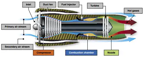
Turbofan:
- Turbofans combine some of the best features of the turbojet and the turboprop []
- The aircraft powered by a turbofan engine has a shorter takeoff distance and produces more thrust during climb-out than a turbojet of approximately the same size, which allows for higher gross weights
- Turbofan engines create additional thrust by diverting a secondary airflow around the combustion chamber
- Because the fan is inside a cowling, the airflow through the fan is unaffected by the aircraft's speed
- The turbofan bypass air generates increased thrust, cools the engine, and aids in exhaust noise suppression
- High-bypass is typically used for efficiency, such as on commercial aircraft
- Low-bypass is typically used for high-speed aircraft, such as military fighters
- Adjusting the bypass provides turbojet-type cruise speed and lowers fuel consumption
- The inlet air that passes through a turbofan engine generally divides into two separate streams of air
- One stream passes through the engine core, while a second stream bypasses the engine core
- Due to a large amount of air that is compressed and accelerated by the fan, the air completely bypasses the burner and turbine sections
- Since the air is not heated by burning fuel to obtain thrust, the turbofan engine has a lower fuel consumption
- It is this bypass stream of air that is responsible for the term "bypass engine"
- A turbofan's bypass ratio refers to the ratio of the mass airflow that passes through the fan divided by the mass airflow that passes through the engine core
- The lower gas velocity as it exits the engine tailpipe also means turbofan engines can run quieter
- Turbofans operate best in low temps, high ambient pressure, and at high RPM
Turboshaft:
- Turboshaft engines deliver power to a shaft via a transmission that drives something other than a propeller (rotor) []
- The biggest difference between a turbojet and a turboshaft engine is that on a turboshaft engine, most of the energy produced by the expanding gases drive a turbine rather than produce thrust
- Possess a high power to weight ratio
- Many helicopters use a turboshaft gas turbine engine
- Axiliary power units on large aircraft are often turboshaft engines
Turbine Engine Operational Considerations
- The great variety of turbine engines makes it impractical to cover specific operational procedures, but there are certain operational considerations common to all turbine engines
-
Engine Temperature Limitations:
- The highest temperature in any turbine engine occurs at the turbine inlet
- Turbine inlet temperature is therefore usually the limiting factor in turbine engine operation
-
Thrust Variations:
- Turbine engine thrust varies directly with air density
- As air density decreases, so does thrust
- Additionally, because air density decreases with an increase in temperature, increased temperatures will also result in decreased thrust
- While both turbine and reciprocating powered engines are affected to some degree by high relative humidity, turbine engines will experience a negligible loss of thrust, while reciprocating engines a significant loss of brake horsepower
-
Auxiliary Power Unit:
- Starting turbine engines requires either external ground equipment or the use of an Auxiliary Power Unit (APU)
- The APU is a small aircraft-mounted gas turbine engine used to generate a source of air to power the air turbine starter(s) or to augment the engine bleed air supply to the Environmental Control System
Foreign Object Debriss
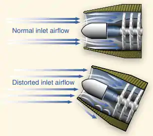
- Due to the design and function of a turbine engine's air inlet, the possibility of ingestion of debris always exists
- This Foreign Object Debris, or FOD, and causes significant damage, particularly to the compressor and turbine sections
- When ingestion of debris occurs, it is called foreign object debris (FOD)
- Typical FOD consists of small nicks and dents caused by ingestion of small objects from the ramp, taxiway, or runway, but FOD damage caused by bird strikes or ice ingestion also occur
- Sometimes FOD results in the total destruction of an engine
- Prevention of FOD is a high priority
- Some engine inlets have a tendency to form a vortex between the ground and the inlet during ground operations
- A vortex dissipater may be installed on these engines
- Other devices, such as screens and/or deflectors, may also be utilized
- Preflight procedures include a visual inspection for any sign of FOD
Powerplant Malfunctions and Emergencies
- Powerplant emergencies can range from minor degradation to all out engine failure
- Engines run on air and fuel
- Since air is practically a given, when an engine fails benignly, suspect fuel
- The FAA published advisory circular 20-105 to provide recommendations on best practices to prevent accidents
- Regardless, treat everything as if it will lead to an engine failure
- Consider thinking of the memory aid: glide, grass, and gas.
-
Catastrophic Engine Failure:
- Although uncommon, catastrophic engine failures are when an engine comes apart in flight
- Any oil that escapes the cowling and impacts the windscreen is likely to blur the windscreen and won't simply blow off
- In this instance, enhanced vision systems are life-savers
- When selecting an off-airport landing site, consider: wind, space, obstacles, and surface condition
- Consider the memory aid of "A-B-C-D-E" whereby you pitch for AIRSPEED, fly at BEST GLIDE, run the CHECKLIST, and finally DECLARE AN EMERGENCY, as appropriate, and EXECUTE the landing
- Pilots should not conduct simulated engine failures below 500' AGL or as prescribed by FAR 91.119, whichever is higher
- Likewise, simulated landings should not be continued below 5,00' AGL unless at an approved airport where the aircraft is in a position to land and the landing will not interfere with other traffic
- Some avionics provide glide rings to inform the pilot what is and is not within range based on altitude, aircraft performance, environmentals, etc.
-
High Cylinder Head Temperature:
- High temperatures of any kind are cause for concern
- High cylinder head temperatures are cause for concern about your engine
-
High Cylinder Head Temperature Indications:
- Your cylinder head temperature gauge will operate high than normal, though not yet necessarily in a 'red' area
-
High Cylinder Head Temperature Secondary Indications:
-
High Cylinder Head Temperature Considerations:
- Insufficient air is getting into the engine cowling calling for reduced pitch, increased speed, open cowl flaps, or a removal of a blockage
- Improper fuel-to-air mixture ratio (lean mixtures could run hotter)
- Equipment failure (spark plugs, magnetos)
- Expect engine power to decrease
- Eexpect egine oil consumption to increase
- Left uncorrected, detonation and pre-ignition may start occurring, exacerbating the problem
-
Engine Failure:
- With engine failures, speed (trading speed for altitude) is life, and altitude (time) is life insurance
- Engine failures are largely due to mechanical failure, loss of spark, loss of air, or loss of fuel
- Engine failures require immediate action
- You should always have a plan, based on phase of flight, before you take off
-
Engine Failure Primary Indications:
- Dropping, low, or no RPM
-
Engine Failure Secondary Indications:
- Dropping temperatures and pressures
- Reduced noise from the engine
-
Engine Failure Considerations:
- Consider an action just performed may be the source of the problem
- There may be enough time to restart the engine
- Altitude is important, but without the appropriate airspeed you will lose too much altitude or stall
- As part of takeoff, engine failure must be discussed in as much detail as practical with altitudes and turning limitations
- Electrical abnormalities may distract the pilot from engine abnormalities, leading to improper immediate action procedures
- Following an engine failure you will lose several systems such as the vacuum system which will result in a partial panel situation
- Loose mixture controls may slowly move to idle
- Sometimes the engine is receiving too much fuel (esp. at higher altitudes), resulting a flooded engine that requires leaning, counter to most conventional engine failure immediate actions
- A partially open primer allows raw fuel to get into the engine intake without atomizing as required for proper combustion
- Loss of the alternator will mean you're running off battery power which is limited to the condition of the battery
- If conducting an off-field landing, remember that magneto wires can be broken leading to a hot mag
- Make your landing crash as slow and as controlled as possible
- Deceleration impacts increase as the square of the speed
- Impact forces at 60 kts are four times those at 30 kts
- At 45 kts only 9.4 feet of deceleration will bring you to a stop
- Deceleration impacts increase as the square of the speed
- Losing situational awareness and stalling the aircraft is far more lethal than the emergency landing
- Engine Failure on Takeoff:
- Pilots must have a plan for engine failure on takeoff before they take the runway
- Failure to obtain and/or maintain flying speed is a leading cause of accidents, so fly the aircraft at the appropriate speed first and foremost
- Turning back to the departure runway (often referred to as the impossible turn) is a highly dangerous maneuver.
- The FAA now states matter-of-factly in Advisory Circular 61-83J that flight instructors should demonstrate and teach trainees when and how to make a safe turnback to the field after an engine failure
- The impossible turn is only impossible if you do not have the performance, so know when you do, and practice-don't guess!
- Every factor impacts the performance required to successfully turn-around and land after takeoff, requiring careful consideration as to conditions practiced and conditions faced
- Whether you can do a turnaround is dependent on the aircrafts climb relative to glide performance
- The closer they are, the better chance you can perform the maneuver, but glide ratio is not all there is to consider
- Aircraft that climb and glide at relatively higher airspeeds will be further from the airport and eat up more distance in the turns, resulting in a reduced likelyhood of success
- Pilots have a tendency to get uncoordinated when turning fast to be able to see the runway
- This turn in and of itself increases accelerated stall speed and therefore risk
- Turn direction should be into the wind and briefed as much on the takeoff brief
- Part of the brief should also include whether a turn back is even an option
- Note that best glide speed changes with weight, but range will remain constant to technique performed
- Be sure to feather (if available) the propeller
- In multi-engine aircraft, use a call-out similar to "Identify, Verify, Feather" where identify is putting your hand on the feather for the correct engine, verifying is verification (potentially from another crewmember, and feather is the action
-
Night Considerations:
- Flying higher provides more time and range to solve the problem or find a safe location for landing
- Consider checkpoints along route that favor landing spots (i.e., airports)
- Spatial disorientation may be more likely if panicked, moving fast, etc.
- Tree landings are more survivable than many would expect
- Consider the use of synthetic vision when possible
- Pilot Workshops provides a night landing scenario with considerations in an emergency landing with no light
-
Multi-Engine Considerations:
- If an engine catches fire, it will generate less power until failure, resulting in sudden yaw
-
Engine Failure Prevention:
- Ensure sufficient fuel quantity (between all tanks), type
- Avoid changing fuel tanks (on selector driven aircraft) away from suitable ditch points
- Mark navlogs when fuel selectors are swapped
- Minimize actions that could foul spark plugs, like running excessively rich
-
Best Glide:
- When you're trying to stretch the range of an aircraft with no engine, fly best glide airspeed
- The closer you can nail the airspeed but if you're task saturated, +/- 5 knots should be acceptable in order to not fixate on the airspeed indicator causing other airwork or procedures to lag behind
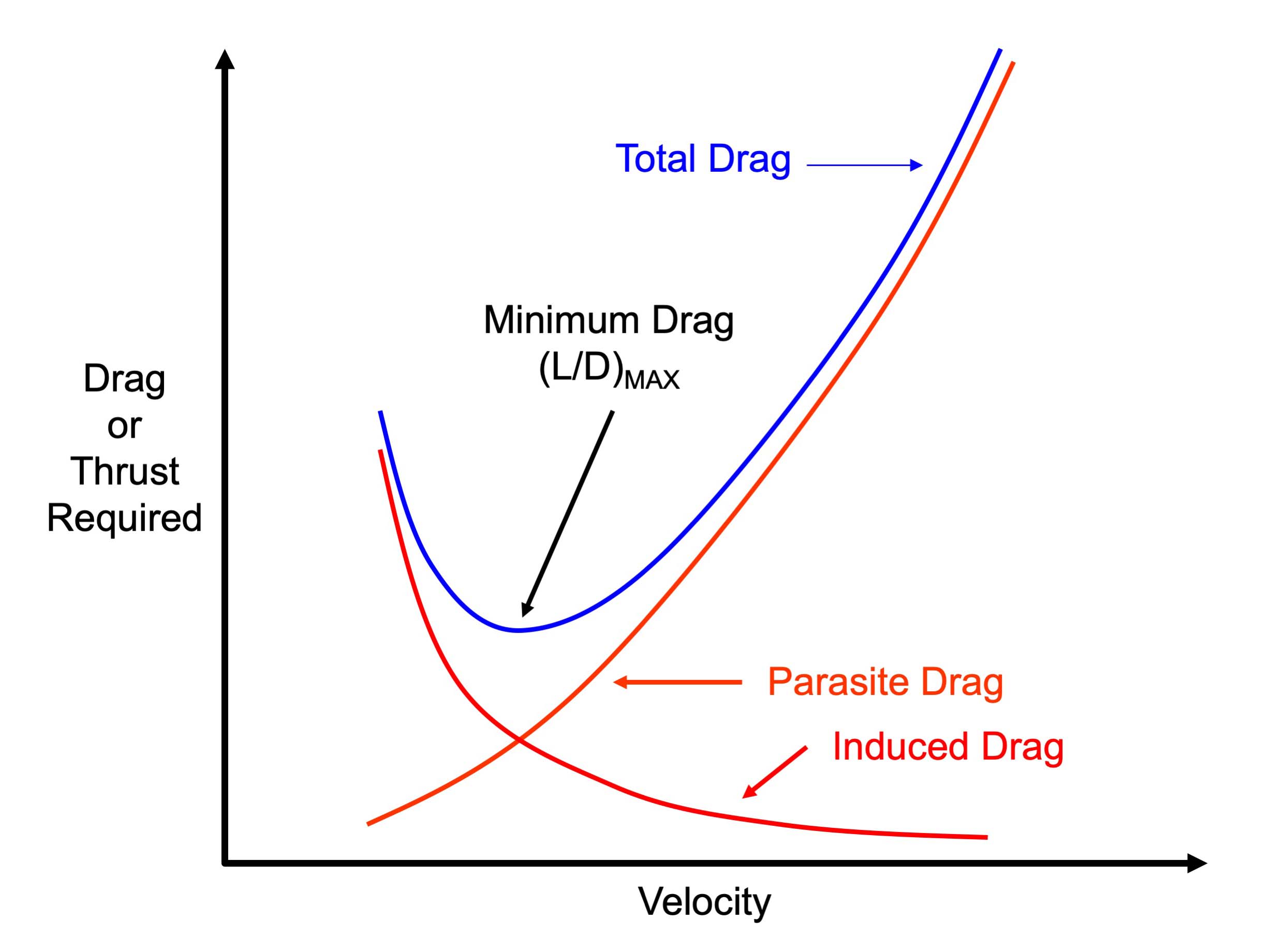
- Best glide is THE best glide airspeed (occurring where total drag is least)
- Pulling up the nose will cause the aircraft to shift on the drag curve toward higher induced drag
- Lowering the nose will cause the airspeed to shift on the drag curve toward higher parasite drag
- In both cases the result is an increased rate of descent!
-
Selecting a Landing Area:
- It would make sense to say that we want to land on a runway, or a piece of terrain that most closely mirrors
- From the air however, this can be challenging and even more-so if you're over terrain you're not familiar with, its dark, or you're in the clouds
- See also:BoldMethod - Your Engine Just Quit, Should You Land On A Road Or A Field?.
- Be sure to tighten seat belts and shoulder harnesses as appropriate when making an emergency landing
-
Partial Power:
- If experiencing a partial power situation, consider and recent changes made, such as switching fuel tanks or mixture modifications
- Aircraft, if trimmed, will pitch down to compensate for loss in airspeed
- Slow to best glide or minimum sink, depending on which is most appropriate
- Set up for an emergency landing with the expectation that a full power loss can happen at any time
-
Stuck Throttle:
- Throttle inputs may stick, causing the engine to be unresponsive to pilot controls
- Throttles can stick anywhere along the range of travel, but are generally considered as high, mid, or low
-
Stuck Throttle (High):
- Stuck throttle high occurs when the engine is stuck at a high power setting, generally relative to cruise settings
-
Stuck Throttle (High) Primary Indications:
- Throttle remains high when lever retarded
-
Stuck Throttle (High) Considerations:
- Consider flying to a point of intended landing and performing a power-off 180.
-
General Stuck Throttle Considerations:
- In most situations, a stuck throttle will result in a power-off landing (when cutting mixture to reduce thrust)
-
Magneto Failure:
- Magnetos failures cause one of the spark plugs in a cylinder to stop firing
- The cylinder effected will experience a higher than average EGT
-
Overheating:
- Engines can overheat due to a failed cooling system or operations prohibiting effective heat management
- In turbine engines, engines may be cooled by motoring the engine, thereby moving cool air throughout the engine
- This may also extinguish fires due to fuel leaks
- To better diagnose, consider that cylinders are generally numbered higher as they move from the front of the engine to the back
- In most engines, the right side, as viewed from the cockpit, are odd numbered and the left are even
- Some aircraft are different, and so cylinder placement should be verified if relying on that data to make a decision
-
Engine Fire:
-
Constant-Speed Propeller Feathering:
- Loss of oil pressure will impact constant-speed propellers which utilize oil to control pitch
- In this case, the propeller will begin, if not fully transition to its neutral setting
- In most aircraft, this will mean the aircraft will feather, and no longer produce thrust
-
Propeller Overspeed:
- Loss of oil pressure may first present itself in propeller overspeed in constant speed propellers
- Reduce the throttle
- Reduce pitch, as able
-
Fuel Delivery:
- Within fuel-related accidents, fuel exhaustion and fuel starvation continue to be leading causes
- From 2011 to 2015, an average of more than 50 accidents per year occurred due to fuel management issues
- Fuel exhaustion accounted for 56% of fuel-related accidents while fuel starvation was responsible for 35% of these accidents
-
Fuel Delivery Primary Indications:
- Rough engine
-
Fuel Delivery Secondary Indications:
- Dropping or low RPM
-
Fuel Delivery Considerations:
- If fuel delivery is not sufficient to keep the engine running smoothly, the engine may be about to quit
- Within fuel-related accidents, fuel exhaustion and fuel starvation continue to be leading causes
-
Hot Start:
- When the EGT exceeds the safe limit of a turbine-powered aircraft, the engine experiences a "hot start"
- Hot starts occur when too much fuel enters the combustion chamber or turbine RPM is insufficient
- Hot starts are caused by improper starting procedures which may be cause of the pilot or electronically controlled systems
- Any time an engine has a hot start, refer to the AFM/POH or an appropriate maintenance manual for inspection requirements
- If the engine fails to accelerate to the proper speed after ignition or does not accelerate to idle RPM, a hung or false start has occurred
- Reciprocating engines may be hot when start, but these procedures are deviations, and not usually cause for concern
-
Hot Start Primary Indications:
-
Hot Start Secondary Indications:
- Engine smoke or fire
-
Hot Start Considerations:
- Be prepared to turn off the engine
- Note dark colored smoke is most often attributed to gas or oil while white smoke is likely electrical
- Aging magnetos may show as the increased frequency of hot, or at least hotter, starts
-
Hung Start:
- A hung start is typically associated with turbine engines
- A hung start occurs when there is insufficient starting power source or fuel control malfunction
-
Hung Start Primary Indications:
- Rising Exhaust Gas Temperatures.
-
Hung Start Secondary Indications:
- RPM does not rise
- The engine fails to start
-
Hung Start Considerations:
- Hung starts may be an indication of a weak or disconnecting starter
-
Tachometer Failure:
- Tachometers can fail, be it the instrument, or connections that feed the instrument display
- Listen to the powerplant, and determine if it is in fact the engine (see engine failure) or the instrument malfunctioning
- The instrument is the only direct reading of RPM the pilot has, which means even if the engine sounds healthy, the engine or the tachometer are unairworthy
- See also: First XC Solo didn't go as planned.
-
Flameout:
- A flameout occurs in the operation of a gas turbine engine in which the fire in the engine unintentionally goes out
- If the fuel/air ratio in the combustion chamber exceeds the rich limit, the flame will blow out
- It generally results from very fast engine acceleration, in which an overly rich mixture causes the fuel temperature to drop below the combustion temperature
- Insufficient airflow to support combustion contribute to flameouts
- A more common flameout occurrence is due to low fuel pressure and low engine speeds, which typically are associated with high-altitude flight
- This situation may also occur with the engine throttled back during descent, which can set up the lean-condition flameout
- A weak mixture can easily cause the flame to die out, even with a normal airflow through the engine
- Any interruption of the fuel supply can result in a flameout
- This may be due to prolonged unusual attitudes, a malfunctioning fuel control system, turbulence, icing, or running out of fuel
- Symptoms of a flameout normally are the same as those following an engine failure
- If the flameout is due to a transitory condition, such as an imbalance between fuel flow and engine speed, correct the situation and attempt an air-start
- In any case, pilots must follow the applicable emergency procedures outlined in the AFM/POH
- Generally, these procedures contain recommendations concerning altitude and airspeed where the air-start is most likely to be successful
-
Compressor Stalls:
- Compressor blades are small airfoils and are subject to the same aerodynamic principles that apply to any airfoil
- A compressor blade has an angle of attack, which is a result of inlet air velocity and the compressor's rotational velocity
- These two forces combine to form a vector, which defines the airfoil's actual angle of attack to the approaching inlet air []
- A compressor stall is an imbalance between the two vector quantities, inlet velocity, and compressor rotational speed
- Compressor stalls occur when the compressor blades' angle of attack exceeds the critical angle of attack
- At this point, smooth airflow is interrupted, creating turbulence with pressure fluctuations
- Compressor stalls cause air flowing in the compressor to slow down and stagnate, sometimes reversing direction [Figure 6-28]
- Compressor stalls can be transient and intermittent or steady and severe
- Indications of a transient/intermittent stall are usually an intermittent "bang" as backfire, and flow reversal take place
- If the stall develops and becomes steady, strong vibration and a loud roar may develop from the continuous flow reversal
- Often, the flight deck gauges do not show a mild or transient stall, but they do indicate a developed stall
- Typical instrument indications include fluctuations in RPM and an increase in exhaust gas temperature
- Most transient stalls are not harmful to the engine and often correct themselves after one or two pulsations
- The possibility of severe engine damage from a steady-state stall is immediate
- Recovery must be accomplished by quickly reducing power, decreasing the aircraft's angle of attack, and increasing airspeed
- Although all gas turbine engines are subject to compressor stalls, most models have systems that inhibit them
- One system uses a variable inlet guide vane (VIGV) and variable stator vanes, which direct the incoming air into the rotor blades at an appropriate angle
- To prevent air pressure stalls, operate the aircraft within the parameters established by the manufacturer
- If a compressor stall does develop, follow the procedures recommended in the AFM/POH
- These occur in turbine engines using the same principles as aircraft wing stalls.
- Turbine engine compressors have an airfoil shape, and when the airflow is disturbed, it causes a stall which creates pressure issues, leading to visible and audible stalls
-
EGT Deviations:
- EGT deviations may be noticeable with the use of an engine monitor
- Temperature anomalies could be the caues of an induction problem
Performance Comparison
- It is possible to compare the performance of a reciprocating powerplant and different types of turbine engines []
- For the comparison to be accurate, thrust horsepower (usable horsepower) for the reciprocating powerplant must be used rather than brake horsepower
- Use net thrust for the turbine-powered engines
- Also, aircraft design configuration and size must be approximately the same
- When comparing performance, the following definitions are useful:
-
Brake Horsepower:
- Brake horsepower (BHP) is the horsepower delivered to the output shaft
- Brake horsepower is the actual usable horsepower
-
Net Thrust:
- The net thrust produced by a turbojet or turbofan engine
-
Thrust Horsepower:
- Thrust horsepower (THP) is the horsepower equivalent of the thrust produced by a turbojet or turbofan engine
-
Equivalent Shaft Horsepower:
- Concerning turboprop engines, the sum of the shaft horsepower (SHP) delivered to the propeller, and THP produced by the exhaust gases is measured as equivalent shaft horsepower (ESHP)
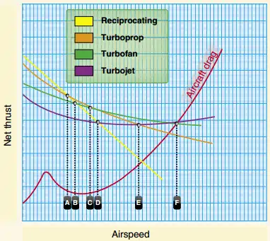
- Figure 6-29 shows how four types of engines compare in net thrust as airspeed is increased
- This figure is for explanatory purposes only and is not for specific models of engines
-
- By plotting the performance curve for each engine, a comparison can be made of maximum aircraft speed variation with the type of engine used
- Since the graph is only a means of comparison, numerical values for net thrust, aircraft speed, and drag are not included
- Comparison of the four powerplants based on net thrust makes certain performance capabilities evident
- In the speed range shown to the left of line A, the reciprocating powerplant outperforms the other three types
- The turboprop outperforms the turbofan in the range to the left of line C
- The turbofan engine outperforms the turbojet in the range to the left of line F
- The turbofan engine outperforms the reciprocating powerplant to the right of line B and the turboprop to the right of line C
- The turbojet outperforms the reciprocating powerplant to the right of line D, the turboprop to the right of line E, and the turbofan to the right of line F
- The points where the aircraft drag curve intersects the net thrust curves are the maximum aircraft speeds
- The vertical lines from each of the points to the baseline of the graph indicate that the turbojet aircraft can attain a higher maximum speed than aircraft equipped with the other types of engines
- Aircraft equipped with the turbofan engine will attain a higher maximum speed than aircraft equipped with a turboprop or reciprocating powerplant
-
Afterburners:
- Afterburners function like a ram-jet whereby atomized fuel mixed with combustion discharge gases/bypass fan discharge air produce additional thrust
- These systems produce about twice the thrust at four times the fuel burn
Powerplant Instrumentation
-
Piston Engine Instrumentation:
-
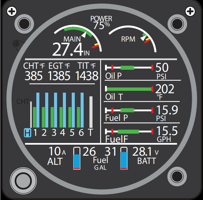
Engine Monitor
- Engine monitors may be installed on most aircraft to precisely measure and log engine parameters
- Engine monitors are direct engine instrumentation that leads to more effective engine management; real-time alarms; and data analysis
- Engine monitors assist pilots when leaning in the climb, leaning using CHT instead of EGT, and operating lean of peak, to name a few
- Engine monitors also allow for cross-checking indications that may be bad sensors, or impending failures
- Pilots must familiarize themselves with a normal baseline:
- Oil temperature should be stable, as regulated by the Vernatherm
- Oil pressure should be stable
-
-
Turbine Engine Instrumentation:
- Engine instruments that indicate oil pressure, oil temperature, engine speed, exhaust gas temperature, and fuel flow are common to both turbine and reciprocating engines
- However, some instruments are unique to turbine engines
- These instruments provide indications of engine pressure ratio, turbine discharge pressure, and torque
- In addition, most gas turbine engines have multiple temperature-sensing instruments, called thermocouples, which provide pilots with temperature readings in and around the turbine section
-
Fuel Flow:
- The pilot of a gas turbine-powered aircraft does not directly control the engine
- The pilot's relation to the power plant corresponds to that of the bridge officer on a ship
- The bridge officer obtains engine response by relaying orders to an engineer below deck, who, in turn, actually moves the throttle of the engine
- The controls sense some or all of the following engine operating variables:
- Pilot's demands (throttle position)
- Compressor inlet temperature
- Compressor discharge pressure
- Burner pressure
- Compressor inlet pressure
- RPM
- Turbine temperature
- Altitude
- Fuel control schedules fuel flow to the engine combustion chamber automatically providing fuel flow as dictated by the operating conditions of the engine
- Fuel flow variations are limited to ensure fast stall-free acceleration and deceleration
-
Engine Pressure Ratio:
- An engine pressure ratio (EPR) gauge indicates the power output of a turbojet/turbofan engine
- EPR is the ratio of turbine discharge to compressor inlet pressure
- Pressure measurements are recorded by probes installed in the engine inlet and at the exhaust
- Once collected, the data is sent to a differential pressure transducer, which is indicated on a flight deck EPR gauge
- EPR system design automatically compensates for the effects of airspeed and altitude. Changes in ambient temperature require a correction to be applied to EPR indications to provide accurate engine power settings
-
Exhaust Gas Temperature (EGT):
- A limiting factor in a gas turbine engine is the temperature of the turbine section
- The temperature of a turbine section must be monitored closely to prevent overheating the turbine blades and other exhaust section components
- One common way of monitoring the temperature of a turbine section is with an EGT gauge. EGT is an engine operating limit used to monitor overall engine operating conditions
- Variations of EGT systems bear different names based on the location of the temperature sensors
- Common turbine temperature sensing gauges include the turbine inlet temperature (TIT) gauge, turbine outlet temperature (TOT) gauge, interstage turbine temperature (ITT) gauge, and turbine gas temperature (TGT) gauge
-
Torquemeter:
- The torquemeter measures turboprop/turboshaft engine power output
- Torque is a twisting force applied to a shaft
- The torquemeter measures power applied to the shaft
- Turboprop and turboshaft engines produce torque for driving a propeller
- Torquemeters are calibrated in percentage units, foot-pounds, or psi
-
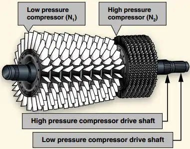
N1 Indicator:
- N1 represents the rotational speed of the low-pressure compressor and is presented on the indicator as a percentage of design RPM
- After start, the speed of the low-pressure compressor is governed by the N1 turbine wheel
- The N1 turbine wheel connects to the low-pressure compressor through a concentric shaft
-
N2 Indicator:
- N2 represents the rotational speed of the high-pressure compressor and is presented on the indicator as a percentage of design RPM
- The N2 turbine wheel governs the high-pressure compressor
- The N2 turbine wheel connects to the high-pressure compressor through a concentric shaft
Powerplant Cooling
- Engines are designed to operate at a specified temperature
- As a result, both under and over-temperature conditions are hazardous to engine health
- Excessive time spent at idle (i.e., rapid descents) can cool an engine below operating temperatures
- In carburetor equipped aircraft, this may result in improper fuel atomization in the carburetor, upsetting the fuel-to-air mixture
- Abrupt (vice smooth/steady) throttle changes exacerbate these situations
Powerplant Knowledge Check


Powerplant Conclusion
- All engines perform the four cycles/stages, but the way they accomplish it will differ
- Powerplants are complex and interact with the other systems in the aircraft
- Note that while a cowling refers to an engine enclosure, a fairing generally refers to other parts of the aircraft, such as the landing gear.
- Engine starting systems are numerous and continue to evolve with technologies like electronic ignition systems.
- Such systems include, but are not limited to:
- If you own an aircraft, consider the installation of a digital engine monitor to not only track engine health, but also better inform troubleshooting when something is not right
- Information relating to your aircraft's specific engine can be found in the aircraft's Pilot Information Manual/Pilot Operating Handbook.
- To learn more about the spiral painted on the front of turbine engines, check out Mentour Pilot on YouTube
- Still looking for something? Continue searching:
Powerplant References
- Airplane Flying Handbook (11-7) Turbocharging.
- Aviation Stack Exchange - What is the difference between Hobbs Time and Tach Time?.
- Federal Aviation Administration - Pilot/Controller Glossary.
- NASA - Engine Lubrication System.
- Pilot Handbook of Aeronautical Knowledge (6-2) Reciprocating Engines.
- Pilot Handbook of Aeronautical Knowledge (6-11) Superchargers and Turbo-superchargers.
- Pilot Handbook of Aeronautical Knowledge (6-20) Turbine Systems.
- Pilot Workshops - A "Correct" Magneto Check?.