Lubrication
Learn aircraft lubrication systems, including engine oil functions, wet- and dry-sump designs, oil pressure and temperature indications, inspections, and malfunctions.
Introduction to Lubrication
- Lubrication systems reduce friction, remove heat, and carry away contaminants produced during engine operation.
- Key highlights summarize the principal oil-system functions and operating concerns.
- Wet-sump and dry-sump oil/lubrication systems lubricate engine components while maintaining proper operating temperature.
- Oil-system design and function explain how the reservoir, engine, and return path work together, while system components regulate, filter, cool, and vent the oil supply.
- Oil-system gauges help pilots interpret pressure and temperature, and operating considerations guide starting, servicing, and monitoring.
- Depending on the aircraft, oil also powers other systems and accessories.
- Oil-system malfunctions require recognizing abnormal indications and following the aircraft's procedures, while inspections help identify oil loss, contamination, and wear.
- The conclusion brings together the operating takeaways, and the references support further study.
- Reinforce your understanding of Lubrication by completing the knowledge quiz and interactive scenario, comparing your performance with the applicable Airman Certification Standards, and reviewing the topic summary before moving on.
Lubrication Key Highlights
- Aircraft lubrication systems reduce friction, dissipate heat, and protect engine components from excessive wear and corrosion.
- Engine oil circulates through internal engine components to provide lubrication, cooling, cleaning, and sealing functions.
- Wet sump and dry sump lubrication systems are commonly used in aircraft engine designs.
- Proper oil pressure and oil temperature are critical indicators of engine lubrication system health and performance.
- Oil filters and screens help remove contaminants that could damage engine components during operation.
- Low oil quantity, contamination, overheating, or pressure loss can lead to severe engine damage or engine failure.
- Pilots should monitor engine instruments carefully for abnormal oil pressure or temperature indications during flight.
- Aircraft manufacturers specify approved oil grades and servicing procedures based on engine design and operating conditions.
- Regular maintenance inspections help identify leaks, contamination, and lubrication system wear before operational problems occur.
- Understanding lubrication systems improves engine management proficiency, systems knowledge, and overall flight safety.
Oil/Lubrication System Design and Function
- Lubrication systems use either a wet-sump or a dry-sump system.
- The distinction is where the oil supply is stored.
- Wet-sump systems store oil in an engine sump, while dry-sump systems store the main oil supply in a separate tank.
-
Wet-Sump Oil/Lubrication Systems:
- In a wet-sump system, a reservoir integral to the engine stores oil. []
- The oil pump draws oil from the sump and delivers it under pressure to engine components.
- After circulating through the engine, oil returns to the sump by gravity.
- In some engines, the rotating crankshaft also splashes oil onto engine components, providing splash lubrication.
-
Dry-Sump Oil/Lubrication Systems:
- Oil is stored in a separate tank and circulated through the engine by pumps.
- The tank includes space above the normal oil level for thermal expansion and foaming.
- A pressure pump draws oil from the separate tank and supplies it to the engine under pressure.
- In a conventional dry-sump system, scavenge pumps return oil from the engine to the oil tank.
- Dry-sump systems can accommodate a larger oil supply without increasing the size of the engine sump, making them suitable for large reciprocating engines.
- Most jet engines use a dry-sump lubrication system.
- Oil remaining in the engine after shutdown can affect a dry-sump tank reading; the required checking interval and oil-return procedure depend on the engine.
- Follow the oil-level checking procedure in the aircraft flight manual (AFM), pilot's operating handbook (POH), and applicable engine instructions.
Oil Circulation:
- The oil reservoir location and return path distinguish wet-sump from dry-sump systems. []
- In a wet-sump system, the pump draws oil from the engine sump through a pickup and suction screen.
- Oil passes through the installed filtering and cooling arrangement before reaching passages called oil galleries that supply bearings and other lubricated parts.
- After lubricating and cooling those parts, oil drains back into the sump by gravity.
- In a conventional dry-sump system, a pressure pump supplies oil from a separate tank to the engine.
- Oil drains into collection sumps, and one or more scavenge pumps return it to the tank.
- The diagram shows a return-line cooler, as in the FAA dry-sump example; cooler location, filter arrangement, and valve routing vary by installation.
- The drawing omits pressure-relief and bypass branches so the storage and return paths remain clear.
- Dry sump does not mean an oil-free engine; oil still lubricates the engine and collects temporarily before returning to the storage tank.
- Not every dry-sump engine uses a scavenge pump.
- For example, the Rotax 912 uses crankcase blow-by pressure to return oil to its external tank; its pressure pump draws oil through the cooler before pumping it through the filter.
- Use the installed engine diagram to identify its actual plumbing and servicing procedure.
- Oil also cushions loaded parts, helps seal piston rings against cylinder walls, and protects internal surfaces against corrosion.
- Its protection depends on oil condition and circulation; an oil film does not prevent corrosion indefinitely during storage.

Lubrication System Components
Oil Pumps and Pressure Regulation:
- The engine-driven pressure pump moves oil through the system; resistance to that flow produces pressure.
- A pressure-relief or regulating valve limits pressure by diverting excess flow to a lower-pressure part of the system.
- The return destination depends on the design; in the wet-sump Lycoming example, excess oil returns to the sump.
- This valve regulates pressure rather than removing contaminants or controlling oil temperature.
Oil Bypass Valves:
- Where installed, a filter bypass valve preserves circulation when the pressure difference across a restricted filter becomes excessive.
- Cold, viscous oil or a contaminated filter can create that restriction.
- Bypassed oil is unfiltered, so bypass protection does not replace scheduled filter inspection and replacement.
- A cooler bypass provides an alternative flow path around the cooler when its design calls for it.
- A thermostatic control manages oil temperature, while a pressure-operated relief feature can protect circulation if the cooler is restricted.
- Some installations combine these functions in one assembly.
- Where installed, a filter bypass valve preserves circulation when the pressure difference across a restricted filter becomes excessive.
Crankcase Ventilation:
- A crankcase breather vents gases that pass the piston rings and enter the crankcase.
- Maintaining the intended vent path prevents excessive crankcase pressure from forcing oil past seals and through other openings.
- Ice or another obstruction can restrict a breather and cause oil loss.
- Some installations use an air-oil separator to recover oil carried in the vent stream.
- Tank vents, separators, and breather outlets must follow the installed design; a vent line is not interchangeable with an oil supply or return line.
- A crankcase breather vents gases that pass the piston rings and enter the crankcase.
-
Oil Filter:
- The oil filter traps debris carried by the circulating oil.
- Oil passes through screens or filter media that trap contaminants.
-
Oil Screens:
- There are two types of oil screens:
- Pressure screens.
- Suction screens.
-
Suction Screens:
- Suction screens are installed before the oil pump to trap larger contaminants before they enter the pump and other components.
-
Pressure Screens:
- Pressure screens trap finer particles than suction screens; the particle size retained depends on the screen design.
- There are two types of oil screens:
-
Paper Oil Filters:
- Paper oil filters use filter media to trap fine particles in the circulating oil.
-
-
Oil Filler Cap/Dipstick:
- The oil filler cap/dipstick used to measure oil quantity is usually accessible through an engine-cowling access panel. []
- If the oil quantity is below the manufacturer's specified operating range, add the approved oil as directed by the aircraft flight manual or pilot's operating handbook.
- If the oil level is unexpectedly low, investigate the cause rather than simply adding oil.
-
Oil:
- Straight mineral oil and ashless-dispersant oil serve different approved applications in piston engines.
- Dispersant additives help keep contaminants suspended until removed with the oil.
- Break-in oil requirements vary by engine; do not assume every new or overhauled engine requires straight mineral oil.
- Single-grade and multigrade oils differ in their viscosity behavior over temperature.
- A multigrade designation such as 15W-50 describes cold-temperature and high-temperature viscosity performance, not two oils in the container.
- Select an approved grade for the manufacturer-specified temperature range; the grade alone does not establish compatibility or approval.
- Turbine engines commonly require approved synthetic turbine oils suited to their operating temperatures.
- Piston-engine and turbine-engine oils are not interchangeable.
- Follow engine and oil-manufacturer instructions for mixing, changing oil types, and additives; neither universal compatibility nor a blanket ban on every mineral/synthetic blend is accurate.
- Select the approved oil type and viscosity grade for the operating conditions specified in the aircraft flight manual and applicable engine instructions. []
- The AFM/POH and applicable placards identify the approved oil type, viscosity grade, and oil quantity limits.
- Straight mineral oil and ashless-dispersant oil serve different approved applications in piston engines.
- Loss of engine oil pressure can cause rapid engine damage and seizure, with or without advance warning from vibration or decreasing engine speed.
- Viscosity is a liquid's resistance to flow.


Heat Management
- Engine oil helps remove heat from engine components.
- Circulating oil absorbs heat from engine components and transfers it to the surrounding air through an oil cooler, when installed, and other exposed system surfaces.
- Where installed, a thermostatic oil-cooler control varies the amount of oil routed through the cooler as temperature changes.
- A cold engine may bypass some or all cooler flow to aid warm-up.
- Hot oil requires both proper circulation and an effective heat sink, such as airflow through an air-oil cooler or fuel flow through a fuel-oil heat exchanger.
Oil System Gauges
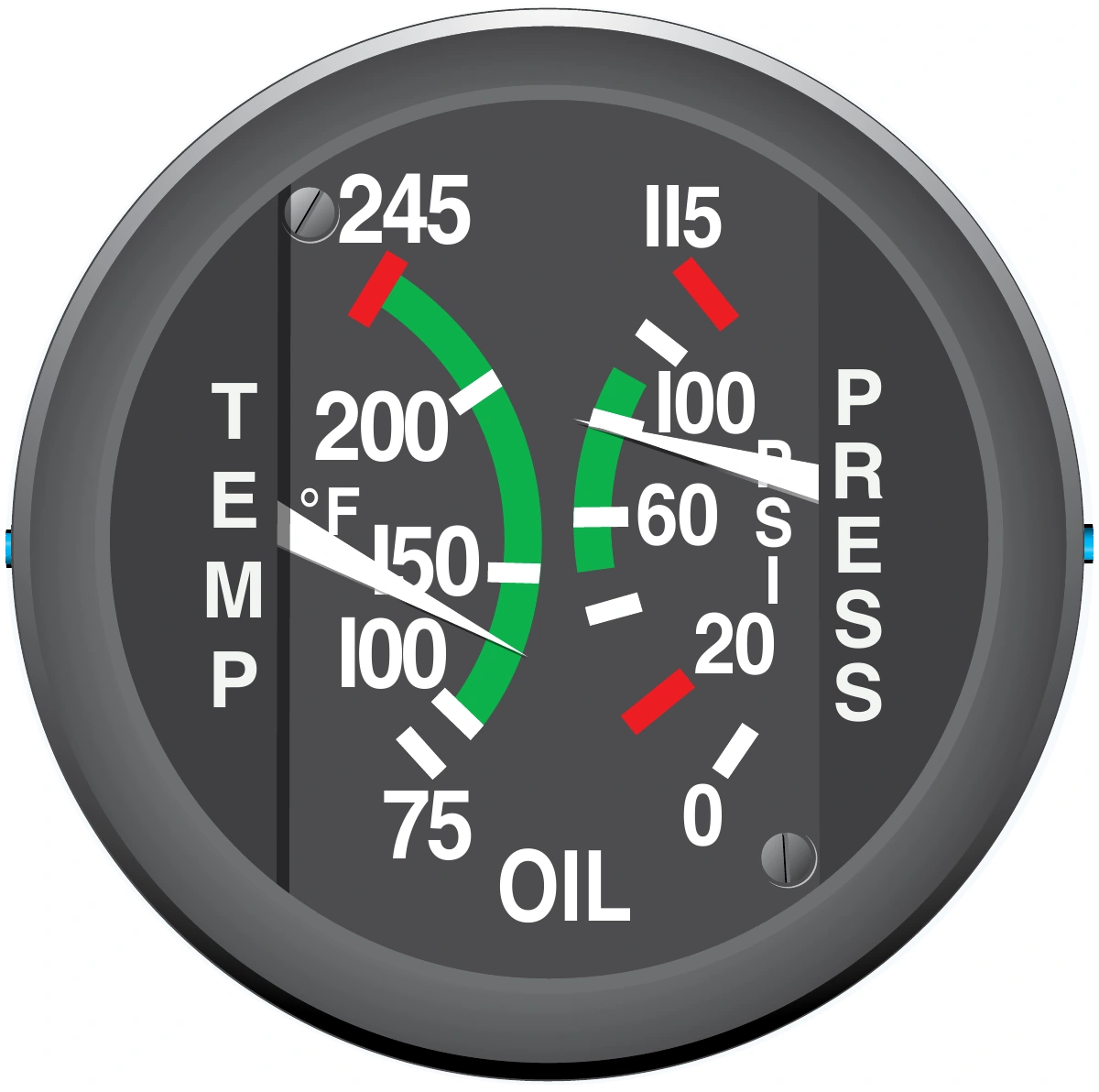
- The oil system is monitored through pressure and temperature gauges.
-
Oil Pressure Gauge:
- The oil pressure gauge indicates oil pressure at the sensing point. []
- Oil pressure is sensed on the pressure side of the pump, typically at the accessory housing or an oil passage in the crankcase, depending on the installation.
- Pressure is commonly displayed in pounds per square inch (psi).
- On a conventional gauge, the green arc identifies the normal operating range and red lines mark pressure limits.
- After engine start, verify that oil pressure rises within the time specified by the manufacturer; shut down as directed by the AFM/POH if it does not.
- Refer to the AFM/POH for oil pressure limits and any permitted starting or warm-up ranges.
-
Oil Temperature Gauge:
- The oil temperature gauge indicates oil temperature at the sensor location. []
- The sensor location varies by installation, but is often downstream of the oil cooler.
- On a conventional gauge, the green arc identifies the normal operating range and the red line marks the maximum allowable temperature.
- Oil temperature generally changes more slowly than oil pressure.
- This is particularly noticeable after starting a cold engine, when it may take several minutes or longer for the gauge to show any increase in oil temperature.
- Monitor oil temperature during flight, particularly in unusually hot or cold conditions.
- High oil temperature indications may signal:
- A restricted oil line or oil cooler.
- Low oil quantity, which may lead to engine damage or failure.
- A faulty temperature sensor or gauge.
- Excessive oil temperature reduces viscosity and can weaken the lubricating film, allowing metal-to-metal contact.
- Low oil temperature may reflect insufficient warm-up, excessive cooling, or an indication fault; the reading alone does not establish that the oil viscosity grade is incorrect.
Oil System Operating Considerations
- Cold oil resists flow, increasing starting loads and potentially slowing lubrication of engine parts.
- Use the approved oil grade and manufacturer-specified preheating procedure.
- Warm up within the published limits rather than increasing power simply to force cold oil through the system.
- After starting, verify the required oil-pressure rise and observe the applicable oil-temperature and pressure limits before takeoff.
- A pressure indication at its sensing point does not prove that every passage has adequate flow.
- Follow the shutdown or abnormal procedure if pressure fails to respond as specified.
- Use the specified servicing quantity, which may differ from the system capacity or minimum operating quantity.
- Allow for the planned flight and expected consumption while staying within approved limits.
- Overfilling can increase oil discharge through the breather in some installations; investigate losses instead of assuming they are normal.
- Track oil added and operating time to identify changes in consumption.
- An increasing trend calls for investigation even if the latest dipstick reading is within limits.
- Remain within the aircraft's approved attitude and acceleration limits.
- A dry sump alone does not make an aircraft suitable for inverted flight.
- Unapproved attitudes can uncover an oil pickup or discharge oil through the breather unless the system has appropriate provisions.
Oil/Lubrication Malfunctions/Emergencies
- Oil consumption depends on engine design, condition, and operating conditions, including seal and piston-ring condition.
- Oil can be lost through internal or external leakage or through faults in the pressurizing or venting system, where installed.
- Rising oil temperature does not always coincide with falling oil pressure or rising cylinder-head temperature (CHT).
- Interpret oil pressure, oil temperature, cylinder-head temperature, engine smoothness, and related indications together; a developing trend or corroborating indication can help distinguish an isolated indication problem from a worsening lubrication or engine condition.
- Low oil pressure may reflect a leak, loss of oil, restricted circulation, pump failure, or an indication-system fault; follow the AFM/POH checklist and plan an early landing rather than assuming the indication is erroneous.
- Low or decreasing oil pressure accompanied by rising oil temperature, engine roughness, or other abnormal indications should be treated as a possible impending engine failure; preserve suitable landing options and be prepared for a partial or complete loss of power.
- High oil temperature with otherwise normal oil pressure can still require prompt action; verify the indication against related instruments, follow aircraft-specific procedures, reduce heat-producing conditions or improve cooling only as directed, and land if the condition does not resolve.
-
Low Oil Pressure:
- Low oil pressure may result from oil loss or a pump malfunction, among other causes.
- On aircraft that use engine oil to operate a constant-speed propeller, loss of oil pressure can also affect propeller pitch control; the response depends on the installation.
-
Low Oil Pressure Primary Indications:
- Oil pressure indicates below the applicable operating limit.
-
Low Oil Pressure Secondary Indications:
- CHT may rise, but a normal indication does not rule out a lubrication problem.
- Oil temperature may rise, but normal oil temperature does not rule out a serious loss of oil pressure, particularly when the pressure drops suddenly.
- Engine roughness or vibration may develop.
-
Low Oil Temperature:
Primary Indications:
- Oil temperature indicates below the applicable operating range.
Secondary Indications:
- Cold, viscous oil may produce higher oil pressure; compare the indications with the AFM/POH warm-up limits.
-
High Oil Temperature:
-
High Oil Temperature Primary Indications:
- Oil temperature indicates above the applicable operating limit.
-
High Oil Temperature Secondary Indications:
- Other engine temperatures may rise, but can remain normal.
- Smoke may accompany an oil leak or severe engine damage.
- Oil pressure may decrease as the oil becomes hotter and less viscous.
-
High Oil Temperature Considerations:
- Follow the AFM/POH high-oil-temperature procedure, including opening cowl flaps when installed and directed.
-
-
Oil Leaks:
- Oil on the windscreen may indicate a leak from the engine or an oil-operated propeller system.
High Oil Pressure:
- High oil pressure may accompany cold, viscous oil or indicate a pressure-regulation, restriction, or indication-system problem.
- Interpret the indication against the engine's cold-start and normal operating limits.
- Follow the AFM/POH response to an out-of-limit indication; do not assume high pressure guarantees adequate lubrication.
- High oil pressure may accompany cold, viscous oil or indicate a pressure-regulation, restriction, or indication-system problem.
Oil Aeration and Restricted Flow:
- Aerated or foaming oil can reduce effective lubrication and disturb pressure indications.
- Dry-sump tanks provide space and internal arrangements for air to separate from returning oil before it reaches the supply outlet.
- A restricted pickup, supply line, or passage can impair circulation even when oil quantity appears adequate.
- Aerated or foaming oil can reduce effective lubrication and disturb pressure indications.
Oil System Inspections
- Inspecting the oil system is an important part of monitoring engine health.
- Changes in oil quantity, consumption, or condition can reveal developing problems.
-
Oil Inspection:
- Inspect the oil as part of the preflight checklist.
- Check both oil quantity and visible condition using the manufacturer's procedure.
- Maintain oil quantity within the AFM/POH operating limits and provide sufficient oil for the planned flight.
- Oil color can provide clues, but color alone does not establish oil condition or engine health.
- Fresh oil is generally lighter in color, but varies with its formulation.
- Oil can darken as it collects contaminants and undergoes oxidation during use.
- Do not use a subjective color threshold in place of the specified oil-change interval or investigation of abnormal findings.
- Excessive combustion-gas leakage past the piston rings can contaminate and darken the oil.
- Larger oil sumps may hold more contaminants in suspension.
- Smaller sumps may be required to be changed/drained more often.
- Follow the applicable oil-change schedule rather than determining the interval from sump size alone.
- Smaller sumps may be required to be changed/drained more often.
- Wet-sump systems commonly use a dipstick to check oil in the engine sump, while dry-sump systems measure oil in a separate tank.
- Use the manufacturer's oil-level checking procedure; dry-sump engines may require a specific shutdown interval or oil-return procedure before checking the tank.
- Some engines, including certain Rotax models, require an oil-return procedure commonly called burping; do not apply that procedure to other engines without manufacturer instructions.
-
Oil Filter Inspection:
- Inspect oil filters and screens at the intervals specified by the applicable maintenance instructions, with the work performed by an authorized person.
- Many oil-filter installations include a bypass valve that maintains oil flow if the filter becomes restricted, allowing unfiltered oil to circulate.
- Replace the filter or clean the screen at the manufacturer's specified intervals, normally as part of scheduled oil changes.
- Inspecting the filter contents at each change helps track engine wear and identify abnormal debris.
Oil Condition and Wear Monitoring:
- Oil analysis and filter inspection provide different evidence of engine condition.
- Laboratory analysis can track small wear particles and contamination, while opening the filter or inspecting a screen can reveal larger debris.
- Compare results with prior samples, operating time, oil additions, and maintenance history rather than treating one sample as a complete diagnosis.
- Where installed, magnetic chip detectors collect ferrous particles and may provide a cockpit warning.
- They do not detect every contaminant or replace filter inspection.
- Follow the aircraft checklist for an indication and the maintenance instructions for evaluating collected material.
- Oil analysis and filter inspection provide different evidence of engine condition.
Lubrication Knowledge Check
Choose the knowledge check that matches your current training for Lubrication.

PPL knowledge check
Core Knowledge Review
Review foundational knowledge, key concepts, and practical considerations. Topic: Lubrication.
- Immediate feedback
- Answer explanations
- Account progress tracking
Sport knowledge check
Sport Pilot Knowledge
Review the foundational knowledge and decisions used in sport-pilot operations. Topic: Lubrication.
- Immediate feedback
- Answer explanations
- Account progress tracking

CPL knowledge check
Advanced Application
Apply knowledge to advanced operations, risk management, and aeronautical decision-making. Topic: Lubrication.
- Immediate feedback
- Answer explanations
- Account progress tracking

CFI knowledge check
Instructor Knowledge
Review the technical knowledge expected of an airplane flight instructor. Topic: Lubrication.
- Immediate feedback
- Answer explanations
- Account progress tracking
Why Take a Quiz?
Quizzes reinforce key concepts, identify knowledge gaps, and build confidence for real-world decisions. Quiz material is representative of the information provided here and is not based on or sourced from the Federal Aviation Administration test bank.
Lubrication Interactive Scenario

The Falling Oil Pressure After Takeoff
Interpret diverging oil indications and make an early landing before an engine warning becomes an engine failure.
Scenario Complete
Aviation Oil/Lubrication System Conclusion
- Oil systems reduce friction, improve sealing, remove heat, and carry away contaminants; some also supply oil to operate other systems.
- Oil analysis and filter inspection complement each other: analysis can track fine wear particles and contamination, while filter inspection can reveal larger debris.
- Some systems pressurize the oil tank to maintain adequate pump inlet pressure and help prevent pump cavitation at high altitude.
- Eligible pilots may change oil as preventive maintenance when the conditions of 14 CFR Part 43 are met, using the applicable procedures and making the required maintenance record entry.
- Oil consumption is relatively low in a gas turbine engine compared to a piston-type engine.
Aviation Oil/Lubrication System References
- AOPA - Understanding Engine Guages.
- Federal Aviation Administration - Advisory Circular (AC) 20-105C Reciprocating Engine Power-Loss Accident Prevention and Trend Monitoring.
- Aircraft Owners and Pilots Association (AOPA) - Oil Screen.
- AOPA - Aircraft Maintenance: Understanding Oil Analysis.
- Federal Aviation Administration - Pilot/Controller Glossary.
- CFI Notebook.net - Pilot Information Manual.
- National Aeronautics and Space Administration (NASA) - Engine Lubrication System.
- Pilot Handbook of Aeronautical Knowledge (6-15) Oil Systems.
- FAA Aviation Maintenance Technician Handbook—Powerplant, Chapter 6: Lubrication and Cooling Systems.
- Lycoming — Oil and Filter Change Recommendations.
- Lycoming — Oil and Your Engine.
- Lycoming — Operating in Cold Weather.
- Rotax — Technical Documentation (installed engine manuals and lubrication-system instructions).