Aircraft Induction Systems
The induction system mixes air and fuel to form the precise mixture necessary for combustion to occur.
Introduction to Aircraft Induction Systems
- The induction system brings in air from the outside, mixes it with fuel, and delivers the fuel/air mixture to the cylinder where combustion occurs
- This combustion creates the thrust or power from the powerplant.
- Outside air enters the induction system through an intake port on the front of the engine cowling
- This port normally contains an air filter that inhibits the entry of dust and other foreign objects
- An alternate air comes from inside the engine cowling, where it bypasses a potential clogged air filter
- Some alternate air sources function automatically, while others operate manually
- Two types of induction systems are commonly used in small aircraft engines:
Aircraft Induction Systems Key Highlights
- Aircraft induction systems supply air to the engine for combustion and engine performance operations.
- Induction systems commonly include air filters, intake ducts, throttle controls, carburetors, fuel injection components, and alternate air systems.
- Proper airflow through the induction system is essential for efficient engine combustion and power production.
- Carburetor icing can restrict airflow and reduce engine performance, especially in moist conditions and moderate temperatures.
- Alternate air systems provide backup airflow if the primary induction source becomes blocked by ice, debris, or contamination.
- Fuel-injected engines generally reduce carburetor icing risk but may still experience induction icing under certain conditions.
- Pilots should monitor engine indications carefully for signs of induction system icing or airflow restriction during flight.
- Induction system malfunctions can lead to power loss, rough engine operation, or complete engine failure.
- Proper use of carburetor heat and induction anti-ice systems improves engine reliability during icing conditions.
- Understanding aircraft induction systems improves systems knowledge, engine management proficiency, and overall flight safety.
Carburetors
- Engines need 3 things to operate: air, fuel, and a spark
- The carburetor mixes the fuel and air before this mixture enters the intake manifold for combustion
- Carburetors are calibrated at sea level meaning, as you increase in altitude, the air pressure is going to go down, while the fuel will remain constant, causing a rich mixture if not fixed
- This can cause fouled spark plugs
- Fuel distribution is not as accurate as fuel injection
- Relatively simple, few moving parts
- Large fuel lines, hard to clog
- Cheap
-
Carburetor Types:
-
Float Type Carburetor:
- The most common type of carburetor. []
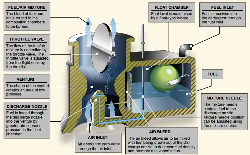
- In the operation of the float-type carburetor system, the outside air first flows through an air filter, usually located at an air intake in the front part of the engine cowling
- This filtered air flows into the carburetor and through a venturi, a narrow throat in the carburetor
- When the air flows through the venturi, a low-pressure area is created, which forces the fuel to flow through a main fuel jet located at the throat
- The fuel/air mixture is then drawn through the intake manifold and into the combustion chambers where it is ignited
- The float-type carburetor acquires its name from a float, which rests on fuel within the float chamber
- A needle attached to the float opens and closes an opening at the bottom of the carburetor bowl
- This meters the correct amount of fuel into the carburetor, depending upon the position of the float, which is controlled by the level of fuel in the float chamber
- When the level of the fuel forces the float to rise, the needle valve closes the fuel opening and shuts off the fuel flow to the carburetor
- The needle valve opens again when the engine requires additional fuel
- The flow of the fuel/air mixture to the combustion chambers is regulated by the throttle valve, which is controlled by the throttle in the flight deck
- Disadvantages:
- Abrupt maneuvers disrupt the float
- Fuel must be discharged at low pressure leading to incomplete vaporization and difficulty discharging fuel into some supercharge systems
- Most importantly, it has an icing tendency discussed below
-
Pressure Type Carburetor:
- A pressure-type carburetor discharges fuel into the airstream at a pressure well above atmospheric via a fuel pump
- This results in better vaporization and permits the discharge of fuel into the airstream on the engine side of the throttle valve
- With the discharge nozzle located at this point, the drop in temperature due to fuel vaporization takes place after the air has passed the throttle valve and at a point where engine heat tends to offset it
- The danger of fuel vaporization icing is practically eliminated
- The effects of rapid maneuvers and rough air on the pressure-type carburetors are negligible since their fuel chambers remain filled under all operating conditions
Mixture Control
- Carburetors are normally calibrated at sea-level pressure, where the correct fuel-to-air mixture ratio is established with the mixture control set in the FULL RICH position
- However, as altitude increases, the density of air entering the carburetor decreases, while the density of the fuel remains the same
- This creates a progressively richer mixture, which can result in engine roughness and an appreciable loss of power
- The roughness normally is due to spark plug fouling from excessive carbon buildup on the plugs
- Carbon buildup occurs because the rich mixture lowers the temperature inside the cylinder, inhibiting complete combustion of the fuel
- This condition may occur during the pre-takeoff run-up at high-elevation airports and during climbs or cruise flight at high altitudes
- To maintain the correct fuel/air mixture, the mixture must be leaned using the mixture control
- Leaning the mixture decreases fuel flow, which compensates for the decreased air density at high altitude
- During a descent from high altitude, the mixture must be enriched, or it may become too lean
- An overly lean mixture causes detonation, which may result in rough engine operation, overheating, and a loss of power
- The best way to maintain the proper mixture is to monitor the engine temperature and enrich the mixture as needed
- Proper mixture control and better fuel economy for fuel-injected engines can be achieved by use of an exhaust gas temperature (EGT) gauge
- Since the process of adjusting the mixture can vary from one aircraft to another, it is important to refer to the airplane flight manual (AFM) or the pilot's operating handbook (POH) to determine the specific procedures for a given aircraft
- When determining to lean, consider aircraft cooling requirements (lean mixtures run hotter), and spark plug fouling (such as idling at high mixture during a long taxi may cause incomplete burning over time)
Carburetor Icing
- Carburetor ice is the biggest disadvantage for a carburetor system. []
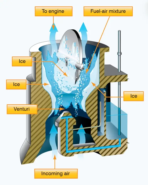
- Carburetor ice is caused due to a sharp temperature drop inside of the carburetor and the vaporization of the fuel
- This occurs due to the effect of fuel vaporization and the decrease in air pressure in the venturi
- Specifically, this is an issue in a float type carburetor system
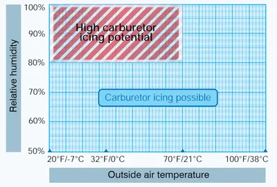
- Carburetor ice can form even with temperatures as high as 100°F (38°C) and humidity as low as 50%. []
- Carburetor ice is most likely to occur when temperatures are below 70° Fahrenheit (°F) or 21° Celsius (°C) and the relative humidity is above 80%
- This temperature drop can be as much as 60 to 70°F (15 to 21°C)
- Therefore, at an outside air temperature of 100°F (37°C), a temperature drop of 70°F (21°C) results in an air temperature in the carburetor of 30°F (-1°C)
- Carburetor icing can occur in all phases of flight
- Carburetor icing will cause a (usually gradual) loss in RPM in fixed-pitch propellers, or shifts in manifold pressure for constant-speed propellers.
- As ice forms in the venturi, RPMs decrease, and so to maintain RPM, the carburetor increases fuel flow
- This increase in fuel flow does nothing because the air flow is the issue
- Therefore, an unexpected rise in fuel flow is the best indication of carburetor ice
- If bad enough, the first indication may be a sudden drop of RPM followed by the engine quitting.
- If water vapor in the air condenses when the carburetor temperature is at or below freezing, ice may form on internal surfaces of the carburetor, including the throttle valve
- The reduced air pressure, as well as the vaporization of fuel, contributes to the temperature decrease in the carburetor
- Ice generally forms in the vicinity of the throttle valve and in the venturi throat
- This restricts the flow of the fuel/air mixture and reduces power
- If enough ice builds up, the engine may cease to operate
- The first indication of carburetor icing in an aircraft with a fixed-pitch propeller is a decrease in engine rpm, which may be followed by engine roughness
- In an aircraft with a constant-speed propeller, carburetor icing is usually indicated by a decrease in manifold pressure, but no reduction in rpm
- Propeller pitch is automatically adjusted to compensate for loss of power
- Thus, a constant rpm is maintained
- Although carburetor ice can occur during any phase of flight, it is particularly dangerous when using reduced power during a descent
- Under certain conditions, carburetor ice could build unnoticed until power is added
- The carburetor heat system is used to reduce the risk of ice with float-type carburetors
- It is important to note that carburetor ice has absolutely nothing to do with structural icing, nor is one an indication of the other


Carburetor Heat
- Carburetor heat is an anti-icing system that preheats the air before it reaches the carburetor, and is intended to keep the fuel/air mixture above the freezing temperature to prevent the formation of carburetor ice
- Note that warmer air is less dense, and will cause a loss of engine performance (~100 RPM)
- Carburetor heat can be used to melt ice that has already formed in the carburetor if the accumulation is not too great, but using carburetor heat as a preventative measure is best
- Additionally, the use of carburetor heat as an alternate air source can be used if the intake filter clogs such as in sudden or unexpected airframe icing conditions
- The carburetor heat should be checked during the engine run-up
- As mentioned above, this less dense air causes a loss of power which is observed during the check as an RPM drop
- When conditions are conducive to carburetor icing during flight, periodic checks should be made to detect its presence
- If detected, full carburetor heat should be applied immediately, and it should be left in the ON position until the pilot is certain all the ice has been removed
- If ice is present, applying partial heat or leaving heat on for an insufficient time might aggravate the situation
- In extreme cases of carburetor icing, even after the ice has been removed, full carburetor heat should be used to prevent further ice formation
- If installed, a carburetor temperature gauge is useful in determining when to use carburetor heat
- Whenever the throttle is closed during flight, the engine cools rapidly and vaporization of the fuel is less complete than if the engine is warm
- Also, in this condition, the engine is more susceptible to carburetor icing
- If carburetor icing conditions are suspected and closed-throttle operation anticipated, adjust the carburetor heat to the full ON position before closing the throttle and leave it on during the closed-throttle operation
- The heat will aid in vaporizing the fuel and help prevent the formation of carburetor ice
- Periodically, open the throttle smoothly for a few seconds to keep the engine warm; otherwise, the carburetor heater may not provide enough heat to prevent icing
- The use of carburetor heat causes a decrease in engine power, sometimes up to 15%, because the heated air is less dense than the outside air (increasing the fuel proportion in the mixture) that had been entering the engine
- Use of carburetor heat will increase density altitude causing it to run overly rich, increasing fuel consumption accordingly
- When ice is present in an aircraft with a fixed-pitch propeller and carburetor heat is being used, there is a decrease in rpm, followed by a gradual increase in rpm as the ice melts
- Engine performance may get worse, before it get's better.
- The engine also should run more smoothly after the ice has been removed
- If ice is not present, the rpm will decrease and then remain constant
- When carburetor heat is used on an aircraft with a constant-speed propeller and ice is present, a decrease in the manifold pressure will be noticed, followed by a gradual increase
- If carburetor icing is not present, the gradual increase in manifold pressure will not be apparent until the carburetor heat is turned off.
- It is imperative for a pilot to recognize carburetor ice when it forms during flight because a loss of power, altitude, and/or airspeed will occur
- These symptoms may sometimes be accompanied by vibration or engine roughness
- Once a power loss is noticed, immediate action should be taken to eliminate ice already formed in the carburetor, and to prevent further ice formation
- This is accomplished by applying full carburetor heat, which will cause a further reduction in power, and possibly engine roughness as melted ice goes through the engine
- These symptoms may last from 30 seconds to several minutes, depending on the severity of the icing. During this period, the pilot must resist the temptation to decrease the carburetor heat usage
- Carburetor heat must remain in the full-hot position until normal power returns
- Since the use of carburetor heat tends to reduce the output of the engine and to increase the operating temperature, carburetor heat should not be used when full power is required (as during takeoff) or during normal engine operation, except to check for the presence or to remove carburetor ice
- Carburetor heat is used to melt or prevent carburetor icing
- Carburetor heat uses unfiltered air
- Air is passed over the exhaust shroud to be heated and then sent through the carburetor
- May be used to overcome clogged intakes, bypassing them
- Procedures vary between aircraft due to different engines having varying degrees of susceptability to icing.
- Always follow the POH procedures and be mindful of different aircraft.
Carburetor Air Temperature Gauge
- Some aircraft are equipped with a carburetor air temperature gauge, which is useful in detecting potential icing conditions
- Usually, the face of the gauge is calibrated in degrees Celsius, with a yellow arc indicating the carburetor air temperatures where icing may occur
- This yellow arc typically ranges between -15°C and +5°C (5°F and 41°F)
- If the air temperature and moisture content of the air are such that carburetor icing is improbable, the engine can be operated with the indicator in the yellow range with no adverse effects
- If the atmospheric conditions are conducive to carburetor icing, the indicator must be kept outside the yellow arc by application of carburetor heat
- Certain carburetor air temperature gauges have a red radial, which indicates the maximum permissible carburetor inlet air temperature recommended by the engine manufacturer
- If present, a green arc indicates the normal operating range
Outside Air Temperature Gauge
- Most aircraft are also equipped with an outside air temperature (OAT) gauge calibrated in both degrees Celsius and Fahrenheit
- It provides the outside or ambient air temperature for calculating true airspeed, and also is useful in detecting icing conditions.
Function
- To ensure a ready supply of fuel, the carburetor has a "float chamber" (or "bowl") that contains a quantity of fuel at near-atmospheric pressure, ready for use
- This reservoir is constantly replenished with fuel supplied by a fuel pump
- The correct fuel level in the bowl is maintained by means of a float controlling an inlet valve
- As fuel is used up, the float drops, opening the inlet valve and admitting fuel. As the fuel level rises, the float rises and closes the inlet valve
- Fuel is forced out of the discharge nozzle into the Venturi due to low pressure
- The level of fuel maintained in the float bowl can usually be adjusted, whether by a setscrew or by something crude such as bending the arm to which the float is connected
- Floats can be made of different materials, such as sheet brass soldered into a hollow shape, or of plastic
- Hollow floats can spring small leaks and plastic floats can eventually become porous and lose their flotation; the float will fail to float, fuel level will be too high, and the engine will not run well unless the float is replaced
- Special vent tubes allow air to escape from the chamber as it fills or enter as it empties, maintaining atmospheric pressure within the float chamber; these usually extend into the carburetor throat
- Must be mounted upright
- Diaphragm carburetors use a flexible diaphragm just like a float
- As fuel is replenished, the diaphragm moves out due to fuel pressure and a small spring, closing the needle valve
- A balanced state is reached, which creates a steady fuel reservoir level, which remains constant in any orientation
Fuel Injection
- Fuel injectors mix the fuel and air immediately before entry into each cylinder or injects fuel directly into each cylinder. []
- In a fuel injection system, the fuel is injected directly into the cylinders, or just ahead of the intake valve
- The air intake for the fuel injection system is similar to that used in a carburetor system, with an alternate air source located within the engine cowling
- This source is used if the external air source is obstructed
- The alternate air source is usually operated automatically, with a backup manual system that can be used if the automatic feature malfunctions
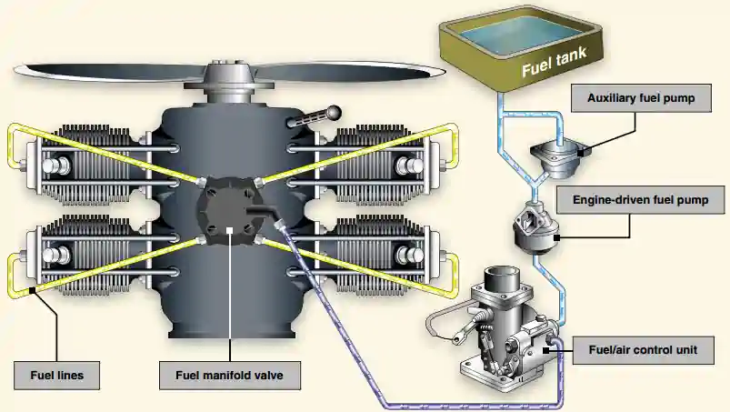
- A fuel injection system usually incorporates six basic components: an engine-driven fuel pump, a fuel/air control unit, fuel manifold (fuel distributor), discharge nozzles, an auxiliary fuel pump, and fuel pressure/flow indicators
- The auxiliary fuel pump provides fuel under pressure to the fuel/air control unit for engine starting and/or emergency use
- After starting, the engine-driven fuel pump provides fuel under pressure from the fuel tank to the fuel/air control unit
- This control unit, which essentially replaces the carburetor, meters fuel based on the mixture control setting, and sends it to the fuel manifold valve at a rate controlled by the throttle
- After reaching the fuel manifold valve, the fuel is distributed to the individual fuel discharge nozzles
- The discharge nozzles, which are located in each cylinder head, inject the fuel/air mixture directly into each cylinder intake port
- A fuel injection system is considered to be less susceptible to icing than the carburetor system, but impact icing on the air intake is a possibility in either system
- Impact icing occurs when ice forms on the exterior of the aircraft, and blocks openings such as the air intake for the injection system
-
Fuel Injection Advantages:
- Reduction in evaporative icing
- Better fuel flow
- Faster throttle response
- Precise control of mixture
- Better fuel distribution
- Easier cold weather starts
-
Fuel Injection Disadvantages:
- Difficulty in starting a hot engine
- Vapor locks during ground operations on hot days
- Problems associated with restarting an engine that quits because of fuel starvation
Air Induction
- Air is necessary for induction and cooling
- Many general aviation aircraft will obtain this air from large openings in the front of the engine
- Some aircraft have an inertial separator to deliver air, but prevent large heavy objects like birds or ice from entering the engine
- Another way is air ducts such as a NACA Duct. []

Air Filter
- Smoke is not harmful to an engine, but will slowly effect the air filter
Private Pilot (Airplane) Operation of Aircraft Systems Airman Certification Standards
- Objective: To determine whether the applicant exhibits satisfactory knowledge, risk management, and skills associated with safe operation of systems on the airplane provided for the flight test.
- References: FAA-H-8083-2 (Risk Management Handbook), FAA-H-8083-3 (Airplane Flying Handbook), FAA-H-8083-23 (Seaplane, Skiplane, and Float/Ski Equipped Helicopter Operations Handbook), FAA-H-8083-25 (Pilot Handbook of Aeronautical Knowledge); POH/AFM.
- Note: If K1 is selected, the evaluator must assess the applicant's knowledge of at least three sub-elements
- Private Pilot Operation of Aircraft Systems Lesson Plan.
Private Pilot (Airplane) Operation of Aircraft Systems Knowledge:
The applicant demonstrates an understanding of:-
PA.I.G.K1:
Airplane systems, including:-
PA.I.G.K1a:
Primary flight controls. -
PA.I.G.K1a:
Secondary flight controls. -
PA.I.G.K1c:
Powerplant and propeller. -
PA.I.G.K1d:
Landing gear. -
PA.I.G.K1e:
Fuel, oil, and hydraulic. -
PA.I.G.K1f:
Electrical. -
PA.I.G.K1g:
Avionics. -
PA.I.G.K1h:
Pitot-static, vacuum/pressure, and associated flight instruments. -
PA.I.G.K1i:
Environmental. -
PA.I.G.K1j:
Deicing and anti-icing. -
PA.I.G.K1k:
Water Rudders (ASES, AMES). -
PA.I.G.K1l:
Oxygen Systems.
-
-
PA.I.G.K2:
Indications of and procedures for managing system abnormalities or failures.
Private Pilot (Airplane) Operation of Aircraft Systems Risk Management:
The applicant is able to identify, assess, and mitigate risks associated with:-
PA.I.G.R1:
Detection of system malfunctions or failures. -
PA.I.G.R2:
Management of a system failure. -
PA.I.G.R3:
Monitoring and management of automated systems.
Private Pilot (Airplane) Operation of Aircraft Systems Skills:
The applicant exhibits the skills to:-
PA.I.G.S1:
Operate at least three of the systems listed in K1a through K1l appropriately. -
PA.I.G.S2:
Complete the appropriate checklist(s).
Private Pilot (Airplane) Systems and Equipment Malfunctions Airman Certification Standards
- Objective: To determine whether the applicant exhibits satisfactory knowledge, risk management, and skills associated with system and equipment malfunctions appropriate to the airplane provided for the practical test
- References: FAA-H-8083-2 (Risk Management Handbook), FAA-H-8083-3 (Airplane Flying Handbook), FAA-H-8083-25 (Pilot Handbook of Aeronautical Knowledge); POH/AFM.
- Private Pilot (Airplane) Systems and Equipment Malfunctions Lesson Plan.
Private Pilot (Airplane) Systems and Equipment Malfunctions Knowledge:
The applicant demonstrates an understanding of:-
PA.IX.C.K1:
Causes of partial or complete power loss related to the specific type of powerplant(s).-
PA.IX.C.K1a:
[Archived]. -
PA.IX.C.K1b:
[Archived]. -
PA.IX.C.K1c:
[Archived]. -
PA.IX.C.K1d:
[Archived].
-
-
PA.IX.C.K2:
System and equipment malfunctions specific to the aircraft, including:-
PA.IX.C.K2a:
Electrical malfunction. -
PA.IX.C.K2b:
Vacuum/pressure and associated flight instrument malfunctions. -
PA.IX.C.K2c:
Pitot/static system malfunction. -
PA.IX.C.K2d:
Electronic flight deck display malfunction. -
PA.IX.C.K2e:
Landing gear or flap malfunction. -
PA.IX.C.K2f:
Inoperative trim.
-
-
PA.IX.C.K3:
Causes and remedies for smoke or fire onboard the aircraft. -
PA.IX.C.K4:
Any other system specific to the airplane (e.g., supplemental oxygen, deicing). -
PA.IX.C.K5:
Inadvertent door or window opening.
Private Pilot (Airplane) Systems and Equipment Malfunctions Risk Management:
The applicant is able to identify, assess, and mitigate risks associated with:-
PA.IX.C.R1:
Checklist usage for a system or equipment malfunction. -
PA.IX.C.R2:
Distractions, task prioritization, loss of situational awareness, or disorientation. -
PA.IX.C.R3:
Undesired aircraft state. -
PA.IX.C.R4:
Startle response.
Private Pilot (Airplane) Systems and Equipment Malfunctions Skills:
The applicant exhibits the skills to:-
PA.IX.C.S1:
Describe appropriate action for simulated emergencies specified by the evaluator, from at least three of the elements or sub-elements listed in K1 through K5 above. -
PA.IX.C.S2:
Complete the appropriate checklist(s).
Aircraft Induction Systems Knowledge Check
Private Pilot

Core Knowledge Review
Review the foundational knowledge, key concepts, and practical considerations for Aircraft Induction Systems.
Foundational
Immediate Feedback
Answer Explanations
Commercial Pilot

Advanced Application
Apply your knowledge of Aircraft Induction Systems to advanced operational scenarios, risk management, and aeronautical decision-making.
Advanced
Scenario Based
Risk Management
Why Take a Quiz?
Quizzes reinforce key concepts, identify knowledge gaps, and build confidence for real-world decisions in the cockpit.
Aircraft Induction Systems Conclusion
- Carburetors are a rare sight with new aircraft but extremely common on your average flight line
- Note that the addition of carburetor heat does impact the engine as the hotter, less dense air, is then combined with fuel
- Failure to lean will result in a richer than previous mixture.
- Still looking for something? Continue searching:
Aircraft Induction Systems References
- Federal Aviation Administration - Pilot/Controller Glossary.
- CFI Notebook.net - Pilot Information Manual.
- CFI Notebook.net - Powerplant.
- CFI Notebook.net - Propeller.
- Pilot Handbook of Aeronautical Knowledge (6-7) Induction Systems.
- Reddit - Why would turning on carb heat make your mixture RICHER?.
- Pilot Workshop - Carb Ice In Summer?.