Relies on vacuum pressure through a vacuum pump to create suction to spin gyroscopes
When the pump is in the beginning of the system, it is referred to as a pressure pump
Directional gyros are almost all air-driven by evacuating the case and allowing filtered air to flow into the case and out through a nozzle, blowing against buckets cut in the periphery of the wheel
Gyro pressure gauge, vacuum gauge, or suction gauge are all terms for the same gauge used to monitor the vacuum developed in the system that actuates the air driven gyroscopic flight instruments
Air is pulled through the instruments, causing gyroscopes to spin
The speed at which the gyros spin needs to be within a certain range for correct operation
This speed is directly related to the suction pressure that is developed in the system
The suction gauge is extremely important in aircraft relying solely on vacuum operated gyroscopic flight instruments
Vacuum is a differential pressure indication, meaning the pressure to be measured is compared to atmospheric pressure through the use of a sealed diaphragm or capsule
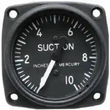
The gauge is calibrated in inches of mercury
It shows how much less pressure exists in the system than in the atmosphere [Figure 1]
Vacuum Systems:
Suction Gauge
In order to overcome the major drawback of the venturi tube, that is, its susceptibility to ice, aircraft were equipped with engine driven vacuum pumps and the gyro instruments were driven by air pulled through the instrument by the suction produced by these pumps
A suction relief valve maintained the desired pressure (usually about four inches of mercury) on the attitude gyro instruments, and a needle valve between one of the attitude indicators and the turn and slip indicator restricted the airflow to maintain the desired 2 inches of suction in its case
Most of the early instruments used only paper filters in each of the instrument cases, but in some installations a central air filter was used to remove contaminants from the cabin air before it entered the instrument case
The early vacuum pumps were vane-type pumps of what is called the wet type-one with a cast iron housing and steel vanes
Engine oil was metered into the pump to provide sealing, lubrication, and cooling, and then this oil, along with the air, was blown through an oil separator where the oil collected on baffles and was returned to the engine crankcase
The air was then exhausted overboard
Aircraft equipped with rubber deicer boots used this discharge air to inflate the boots
But before it could be used, this air was passed through a second stage of oil separation and then to the distributor valve and finally to the boots (See figure 12-2.)
The airflow through the instruments is controlled by maintaining the suction in the instrument case at the desired level with a suction relief valve mounted between the pump and the instruments
This valve has a spring-loaded poppet that offsets to allow cabin air to enter the pump and maintain the correct negative pressure inside the instrument case
The more modern vacuum pumps are of the dry type
These pumps use carbon vanes and do not require any lubrication, as the vanes provide their own lubrication as they wear away at a carefully predetermined rate. Other than the fact that they do not require an oil separator, systems using dry air pumps are quite similar to those using a wet pump. On slight difference, however, is in the need for keeping the inside of the pump perfectly clean. Any solid particles drawn into the system through the suction relief valve can damage one of the carbon vanes, and this can lead to destruction of the pump, as the particles broken off of one vane will damage all of the other vanes. To prevent particles entering the relief valve, its air inlet is covered with a filter, and this must be cleaned or replaced at the interval recommended by the aircraft manufacturer
A physical failure may manifest with the indicator becoming stuck
A vacuum failure may manifest with the instrument acting erratically
Vacuum System Failures:
Vacuum systems are recognized by a low indication on the vacuum gauge or unusual instrument indications
Reduces or eliminates effectiveness of the turn coordinator, attitude indicator, and heading indicator
When the primary air inlet is blocked, the backup inlet automatically opens due to pressure
Occurs when the vacuum pump fails or when both intakes are blocked
Common Training Aircraft Vacuum System Characteristics:
Cessna-172:
Provides "power" to the attitude indicator and directional indicator
The desired suction range is 4.5 to 5.5 inches Hg
Transducers measure vacuum output at each pump
If output of the left or right pump drops below 3.0 in. HG then L VAC R will flash for 10 seconds before becoming steady
There are 2 engine driven vacuum pumps
Piper Arrow:
Protected by a vacuum regulator (protects gyros)
Normal operation reads 4.8 to 5.1 inches of mercury
"Powers" air driven gyro instruments
Vacuum pump is a dry type pump
Zero pressure may indicate a sheered pump drive
Reduction in pressures may indicate dirty filters and screens
Private Pilot - Operation of Aircraft Systems Airman Certification Standards:
Objective: To determine the applicant exhibits satisfactory knowledge, risk management, and skills associated with safe operation of systems on the airplane provided for the flight test.
The applicant is able to identify, assess, and mitigate risk associated with:
PA.I.G.R1:
Detection of system malfunctions or failures
PA.I.G.R2:
Management of a system failure
PA.I.G.R3:
Monitoring and management of automated systems
Operation of Aircraft Systems Skills:
The applicant exhibits the skill to:
PA.I.G.S1:
Operate at least three of the systems listed in K1a through K1l appropriately
PA.I.G.S2:
Complete the appropriate checklist(s)
Private Pilot - Systems and Equipment Malfunctions Airman Certification Standards:
Objective: To determine the applicant exhibits satisfactory knowledge, risk management, and skills associated with system and equipment malfunctions appropriate to the airplane provided for the practical test
Causes and remedies for smoke or fire onboard the aircraft
PA.IX.C.K4:
Any other system specific to the airplane (e.g., supplemental oxygen, deicing)
PA.IX.C.K5:
Inadvertent door or window opening
Systems and Equipment Malfunctions Risk Management:
The applicant is able to identify, assess, and mitigate risk associated with:
PA.IX.C.R1:
Checklist usage for a system or equipment malfunction
PA.IX.C.R2:
Distractions, task prioritization, loss of situational awareness, or disorientation
PA.IX.C.R3:
Undesired aircraft state
PA.IX.C.R4:
Startle response
Systems and Equipment Malfunctions Skills:
The applicant exhibits the skill to:
PA.IX.C.S1:
Describe appropriate action for simulated emergencies specified by the evaluator, from at least three of the elements or sub-elements listed in K1 through K5 above
PA.IX.C.S2:
Complete the appropriate checklist(s)
Vacuum System Case Studies:
Conclusion:
The vacuum system is an important component for many aircraft as it runs instrumentation and potentially other systems
Of note however, is that these systems can be expensive to maintain and there is the option to run many if not all of the systems requiring vacuum on electric