Turn Coordinator
The Turn Coordinator displays the rate of turn and rate of roll information, as well as quality and coordination of the turn.
Introduction to Turn Coordinator
- Turn coordinators display the rate of turn and roll information.
- Designed to function off an electrically or vacuum/pressure driven gyroscope, indicating the quality and coordination of a turn.
- Pilots monitor the instrument's performance on startup and taxi to ensure proper function.
- Newer aircraft utilize modern Inertial Reference Unit (IRU), Inertial Navigation System (INS), and Attitude Heading Reference System (AHRS) systems for glass displays.
- As with any system or instrument, anomalies and malfunctions are possible, requiring detailed knowledge of the indicator and related systems.
Turn Coordinator Key Highlights
- The turn coordinator displays aircraft rate of turn and roll information during flight operations.
- Turn coordinators use gyroscopic principles to sense both roll initiation and turning motion.
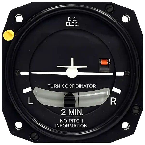
- The miniature aircraft symbol indicates the direction and rate of turn relative to standard-rate turn markings.
- Standard-rate turns normally result in a heading change of approximately three degrees per second.
- The inclinometer, or slip-skid indicator, helps pilots maintain coordinated flight by showing balance between centrifugal force and gravity.
- An aircraft in coordinated flight keeps the inclinometer ball centered during turns and maneuvering operations.
- Turn coordinators are especially important during instrument flight and reduced-visibility conditions.
- Vacuum system failures or electrical malfunctions may affect turn coordinator operation depending on aircraft design.
- Pilots should cross-check turn coordinator indications with other flight instruments to maintain proper aircraft control.
- Understanding turn coordinator operation improves instrument proficiency, coordinated flight control, and overall flight safety.
Turn Coordinator Design and Function
- Turn coordinators provide turn performance indications with a gyroscope. []
- To maintain accuracy, the gyroscope is mounted at a 30° angle.
- The gyro is either electrically or vacuum/pressure driven
- Developed from the turn and bank indicator
- When the aircraft yaws, or rotates about its vertical axis, it produces a force in the horizontal plane that, due to precession, causes the gyro and its gimbal to rotate about the gimbal's axis
- It is restrained in this rotation plane by a calibration spring; it rolls over just enough to cause the pointer to deflect until it aligns with one of the doghouse-shaped marks on the dial, when the aircraft is making a standard rate turn
- A red flag shows the instrument is in a non-operational status
- Inclinometer is located below the instrument used to determine quality of a turn (angle of bank and the rate of yaw)
- The words printed 2-minutes means a standard rate turn held for 2-minutes would result in a 360° turn
- This ball measures the relative strength of the force of gravity and the force of inertia caused by a turn
- Gyroscopically driven using the principle of precession
- A line indicates the standard rate turn
- Mounted with about a 30 - 35° canted on the gyro
- The gyro is mounted in a single gimbal with its spin axis parallel to the lateral axis of the aircraft and the axis of the gimbal parallel with the longitudinal axis
- Slip: rate of turn is too slow for the angle of bank
- Skid: rate of turn is too great for the angle of bank
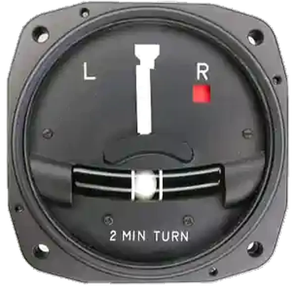
- The turn and slip indicator is an older design, and provides rate of turn and roll information. []
- Because the gyro is mounted along the aircraft's longitudinal axis, yaw and roll information are not provided
- Turn & slip indicators therefore only show rate of turn.
Turn Coordinator Indications
- Turn coordinators precisely indicate the quality of turn, and generally the rate-of-turn.
- Specific rate of turn indications relate to standard rate turns:
- When the miniature aircraft (or the needle is straight up and down), the aircraft is straight and level
- When the miniature aircraft (or needle) is aligned with one of the turn alignment marks, it is in a standard rate turn
- A standard rate turn is defined as an aircraft turning at 3° per second
- This standard turn rate is dependent upon True Airspeed and so the faster an aircraft is moving, the more angle of bank is required to achieve this set 3° rate
- SRT Angle of Bank = [True Airspeed in Knots / 10] + 5
Turn Coordinator Preflight Actions
- Upon engine start and the activation of the gyroscopes (vacuum or electrical system), any flags should disappear.
- As the aircraft begins to taxi, the aircraft should indicate a bank in the direction of taxi turns and the ball inside the inclinometer should deflect outward from the turn.
Inertial Reference Unit (IRU), Inertial Navigation System (INS), and Attitude Heading Reference System (AHRS)
- IRUs are self-contained systems comprised of gyros and accelerometers that provide aircraft attitude (pitch, roll, and heading), position, and velocity information in response to signals resulting from inertial effects on system components.
- Once aligned with a known position, IRUs continuously calculate position and velocity. IRU position accuracy decays with time.
- This degradation is known as "drift."
- INSs combine the components of an IRU with an internal navigation computer.
- By programming a series of waypoints, these systems will navigate along a predetermined track.
- AHRSs are electronic devices that provide attitude information to aircraft systems such as weather radar and autopilot, but do not directly compute position information.
- Aircraft equipped with slaved compass systems may be susceptible to heading errors caused by exposure to magnetic field disturbances (flux fields) found in materials that are commonly located on the surface or buried under taxiways and ramps.
- These materials generate a magnetic flux field that can be sensed by the aircraft's compass system flux detector or "gate", which can cause the aircraft's system to align with the material's magnetic field rather than the earth's natural magnetic field.
- The system's erroneous heading may not self-correct.
- Prior to take off pilots should be aware that a heading misalignment may have occurred during taxi.
- Pilots are encouraged to follow the manufacturer's or other appropriate procedures to correct possible heading misalignment before take off is commenced.
Turn Coordinator Anomalies & Malfunctions
Private Pilot (Airplane) Operation of Aircraft Systems Airman Certification Standards
- Objective: To determine whether the applicant exhibits satisfactory knowledge, risk management, and skills associated with safe operation of systems on the airplane provided for the flight test.
- References: FAA-H-8083-2 (Risk Management Handbook), FAA-H-8083-3 (Airplane Flying Handbook), FAA-H-8083-23 (Seaplane, Skiplane, and Float/Ski Equipped Helicopter Operations Handbook), FAA-H-8083-25 (Pilot Handbook of Aeronautical Knowledge); POH/AFM.
- Note: If K1 is selected, the evaluator must assess the applicant's knowledge of at least three sub-elements
- Private Pilot (Airplane) Operation of Aircraft Systems Lesson Plan.
Private Pilot (Airplane) Operation of Aircraft Systems Knowledge:
The applicant demonstrates an understanding of:-
PA.I.G.K1:
Airplane systems, including:-
PA.I.G.K1a:
Primary flight controls. -
PA.I.G.K1a:
Secondary flight controls. -
PA.I.G.K1c:
Powerplant and propeller. -
PA.I.G.K1d:
Landing gear. -
PA.I.G.K1e:
Fuel, oil, and hydraulic. -
PA.I.G.K1f:
Electrical. -
PA.I.G.K1g:
Avionics. -
PA.I.G.K1h:
Pitot-static, vacuum/pressure, and associated flight instruments. -
PA.I.G.K1i:
Environmental. -
PA.I.G.K1j:
Deicing and anti-icing. -
PA.I.G.K1k:
Water Rudders (ASES, AMES). -
PA.I.G.K1l:
Oxygen Systems.
-
-
PA.I.G.K2:
Indications of and procedures for managing system abnormalities or failures.
Private Pilot (Airplane) Operation of Aircraft Systems Risk Management:
The applicant is able to identify, assess, and mitigate risks associated with:-
PA.I.G.R1:
Detection of system malfunctions or failures. -
PA.I.G.R2:
Management of a system failure. -
PA.I.G.R3:
Monitoring and management of automated systems.
Private Pilot (Airplane) Operation of Aircraft Systems Skills:
The applicant exhibits the skills to:-
PA.I.G.S1:
Operate at least three of the systems listed in K1a through K1l appropriately. -
PA.I.G.S2:
Complete the appropriate checklist(s).
Private Pilot (Airplane) Systems and Equipment Malfunctions Airman Certification Standards
- Objective: To determine whether the applicant exhibits satisfactory knowledge, risk management, and skills associated with system and equipment malfunctions appropriate to the airplane provided for the practical test
- References: FAA-H-8083-2 (Risk Management Handbook), FAA-H-8083-3 (Airplane Flying Handbook), FAA-H-8083-25 (Pilot Handbook of Aeronautical Knowledge); POH/AFM.
- Private Pilot (Airplane) Systems and Equipment Malfunctions Lesson Plan.
Private Pilot (Airplane) Systems and Equipment Malfunctions Knowledge:
The applicant demonstrates an understanding of:-
PA.IX.C.K1:
Causes of partial or complete power loss related to the specific type of powerplant(s).-
PA.IX.C.K1a:
[Archived]. -
PA.IX.C.K1b:
[Archived]. -
PA.IX.C.K1c:
[Archived]. -
PA.IX.C.K1d:
[Archived].
-
-
PA.IX.C.K2:
System and equipment malfunctions specific to the aircraft, including:-
PA.IX.C.K2a:
Electrical malfunction. -
PA.IX.C.K2b:
Vacuum/pressure and associated flight instrument malfunctions. -
PA.IX.C.K2c:
Pitot/static system malfunction. -
PA.IX.C.K2d:
Electronic flight deck display malfunction. -
PA.IX.C.K2e:
Landing gear or flap malfunction. -
PA.IX.C.K2f:
Inoperative trim.
-
-
PA.IX.C.K3:
Causes and remedies for smoke or fire onboard the aircraft. -
PA.IX.C.K4:
Any other system specific to the airplane (e.g., supplemental oxygen, deicing). -
PA.IX.C.K5:
Inadvertent door or window opening.
Private Pilot (Airplane) Systems and Equipment Malfunctions Risk Management:
The applicant is able to identify, assess, and mitigate risks associated with:-
PA.IX.C.R1:
Checklist usage for a system or equipment malfunction. -
PA.IX.C.R2:
Distractions, task prioritization, loss of situational awareness, or disorientation. -
PA.IX.C.R3:
Undesired aircraft state. -
PA.IX.C.R4:
Startle response.
Private Pilot (Airplane) Systems and Equipment Malfunctions Skills:
The applicant exhibits the skills to:-
PA.IX.C.S1:
Describe appropriate action for simulated emergencies specified by the evaluator, from at least three of the elements or sub-elements listed in K1 through K5 above. -
PA.IX.C.S2:
Complete the appropriate checklist(s).
Turn Coordinator Knowledge Check


Turn Coordinator Conclusion
- Always keep in mind the effects of parallax error.
- Still looking for something? Continue searching:
Turn Coordinator References
- AOPA - How it Works: Turn Coordinator.
- Federal Aviation Administration - Pilot/Controller Glossary.
- Aeronautical Information Manual (1-1-15) Inertial Reference Unit (IRU), Inertial Navigation System (INS), and Attitude Heading Reference System (AHRS).
- CFI Notebook.net - Electrical System.
- Instrument Flying Handbook.