Airspeed Indicator
The airspeed indicator is a Pitot-static instrument used in an aircraft to display the craft's airspeed, typically in knots to the pilot.
Introduction to Airspeed Indicator
- The Airspeed Indicator (ASI) displays the aircraft's airspeed, typically in knots.
- The airspeed indicator measures the differential pressure between the impact/dynamic pressure and static pressure by utilizing the Pitot-static system.
- The instrument's design translates pressure to mechanical movement through the airspeed dial.
- Airspeed indications, usually displayed in knots, display or reference different types of airspeed, referred to as "v-speeds."
- Airspeed indicators are considered critical instrumentation, and before a flight, pilots must consider the regulations and conduct preflight actions to ensure performance and reliability.
- Newer aircraft often maintain backup airspeed indicators but are equipped with modern Inertial Reference Unit (IRU), Inertial Navigation System (INS), and Attitude Heading Reference System (AHRS) systems for glass displays.
- As with any system or instrument, anomalies and malfunctions are possible, requiring detailed knowledge of the indicator and related systems.
- Think you've got a solid understanding of the airspeed indicator? Don't miss the airspeed indicator quiz below, and topic summary.
Airspeed Indicator Key Highlights
- The airspeed indicator measures aircraft speed through the air using pitot and static pressure inputs.
- Indicated airspeed is the primary reference pilots use for aircraft control, performance management, and operating limitations.
- The pitot-static system compares ram air pressure from the pitot tube with static air pressure to calculate airspeed.
- Color-coded markings on the airspeed indicator identify operating ranges, caution ranges, and aircraft limitations.
- Types of airspeed include indicated, calibrated, true, equivalent, and groundspeed, each serving different operational purposes.
- Blocked pitot tubes or static ports can cause inaccurate airspeed indications and instrument system malfunctions.
- Temperature, altitude, and atmospheric conditions affect true airspeed and aircraft performance.
- Pilots should monitor airspeed continuously during takeoff, climb, cruise, descent, approach, and landing operations.
- Modern electronic flight displays present airspeed information digitally while relying on the same pitot-static principles.
- Understanding airspeed indicator operation improves aircraft control, performance management, and overall flight safety.
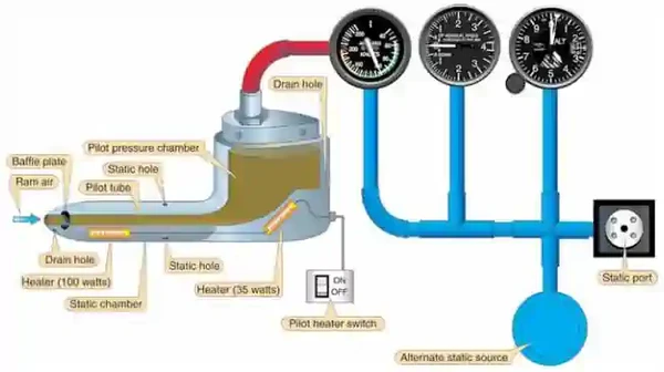
Pitot-Static System
- Pitot Static systems measure and compare air pressures from the Pitot tube and static port
- These measurements display indications for the Airspeed Indicator (ASI), Altimeter, and Vertical Speed Indicators (VSI).
- The system consists of two components:
-
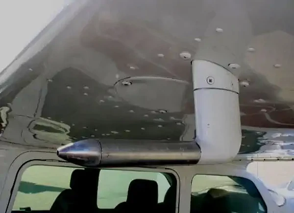
Pitot Tube:
- Invented by Henri Pitot in 1732, the Pitot tube measures fluid flow (air) velocity.
- The device measures ram (forced) air through a small hole in its front.
- The device's placement is often on the front of the aircraft or an airfoil to capture smooth (undisturbed) air. []
- The ram air captured produces an airspeed reading on the airspeed indicator (ASI).
-
Pitot Heat:
- Pitot Tubes are often electrically heated, which can prevent and remove ice accumulation. []
- Note that these devices should only be utilized during ground operations when necessary.
- Leaving them on unnecessarily can cause heat to the point of damage/malfunction.
- When airborne, the airflow otherwise cools the device.
-
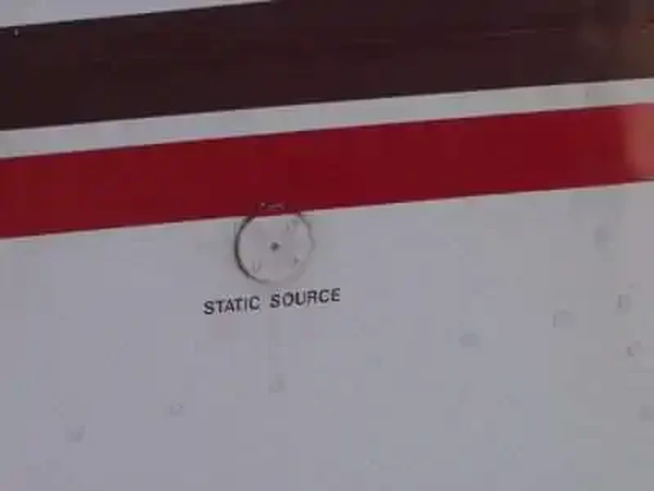
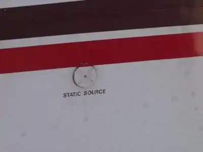
Static Port:
- Static ports measure ambient still-air atmospheric pressure.
- Typically, ports are flush mounted on the side of the aircraft where air is undisturbed. []
- Some aircraft may utilize heated static ports to mitigate ice.
- Dual ports remove errors due to slips and skids.
- Responsible for Airspeed Indicator, Altimeter, and Vertical Speed Indicators.
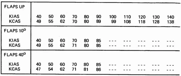
- The POH/AFM contains any corrections to the airspeed for the various flaps and landing gear configurations.
-
Alternate Static Source:
- An alternate static air source valve is available for emergencies on some aircraft.
- If the alternate source ports inside the airplane, where static pressure is usually lower than outside, selection may result in the following erroneous instrument indications:
- The altimeter reads higher than normal.
- Indicated airspeed (IAS) reads greater than normal.
- VSI momentarily shows a climb.
- Many POHs provide a correction table and aircraft-specific instructions.
- The alternate static source is not corrected for non-standard pressure (as with an altimeter's Kollsman window).
- Using alternate static sources may impact other instruments that rely on static pressure (i.e., autopilots, TCAS, transponder, etc.).
- Using alternate static sources can also decrease the accuracy beyond the 75 feet recommendation outlined in the Aeronautical Information Manual.


Airspeed Indicator Design and Function
- Airspeed indicators are instruments, typically mechanical in build, that measure an aircraft's through the air ("airspeed") to a pilot.
- Airspeed indicators function by comparing impact/dynamic pressure ("ram air") to the static air pressure to display an airspeed. []
- Impact/Dynamic pressure ("ram air") is the air captured through the opening of the Pitot tube.
- Ram air is also referred to as total pressure.
- Dynamic pressure is the difference between the static (ambient) air pressure and the total pressure caused by the aircraft's motion through the air.
- Pitot tubes are often electrically heated to prevent ice buildup from blocking the inlets.
- The static pressure enters through the static port(s) located on the side of the fuselage.
- The installation location most accurately detects prevailing atmospheric pressure (parallel to the air stream) and avoids dynamic (ram) air pressure.
- Some aircraft will have more than one port to measure pressure during slips and skids accurately.
- Most aircraft have an alternate static source intended for use when the primary static source is blocked.
- Although less accurate, alternate static sources provide backup in an emergency, such as in instrument meteorological conditions (IMC).
- Impact/Dynamic pressure ("ram air") is the air captured through the opening of the Pitot tube.
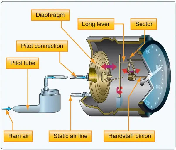
- Conservation of Energy states that total pressure must remain the same; therefore, a diaphragm compares pressures.
- The diaphragm expands as the Pitot pressure increases or the static pressure decreases (relative to ram air pressure).
- The diaphragm expands as the Pitot pressure decreases or the static pressure increases (relative to ram air pressure).
- The diaphragm's dimensional change moves a rocking shaft and gears that drive a pointer across the instrument dial. []

Airspeed Indications
- Airspeed indication uses a thin, corrugated phosphor bronze diaphragm (aneroid), which measures the dynamic pressure of the air between the Pitot tube (ram air) and static port (static pressure).
- The instrument has numbers that run the perimeter of the indicator, which indicates the airspeed.
- Unless otherwise noted in the AFM/POH, they apply to seal level, standard day conditions at maximum takeoff weight.
- Performance speeds vary with aircraft weight, configuration, and atmospheric conditions.
- Airspeed is generally displayed as a Knot (Kt) but may be in Miles per Hour (MPH) or Kilometers per Hour (KPH).
- A knot is a unit for the speed measured in Nautical Miles per Hour (NM/Hr).
- A knot is slower than MPH and KPH.
- 1 Kt = 1.15 MPH = 1.85 KPH.
- Airspeed may also be presented as calibrated airspeeds (CAS) or indicated airspeeds (IAS).
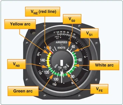
- Also, along the outer rim of the instrument are a series of arcs. []
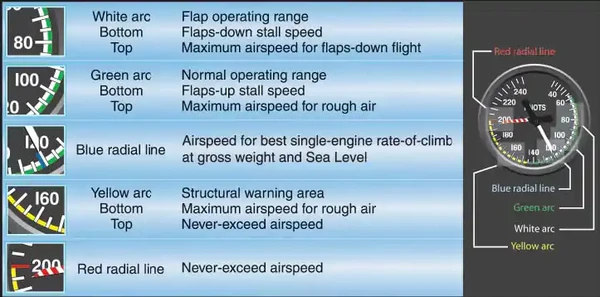
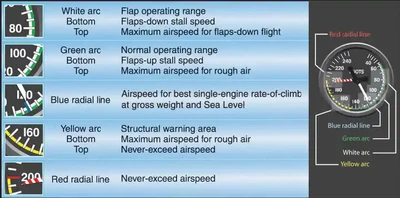
- The white arc indicates flap operation speed, with the bottom indicating the flaps-down stall speed and the top of the arc indicating the maximum flap operating speed.
- The green arc indicates the normal operating range, with the bottom being the no-flap stall speed and the top being the maximum airspeed through rough air.
- The yellow arc indicates the structural warning area.
- The red arc indicates the never-exceed speed.
- A blue line (if present) indicates the best single-engine climb speed for twin-engine aircraft at gross weight at sea level.
Airspeed V-Speeds
- V-speeds are airspeeds of significance to the pilot during flight. []
- These speeds differ between aircraft and are specified in the Pilot Operating Handbook/Pilot Information Manual (POH/PIM) under the performance specifications.
- To avoid confusion, this is a list of definitions, should you need them.
- These do not apply to every aircraft you fly.
- Pilots should use this information to reference the POH and reference unknown speeds against what they mean.
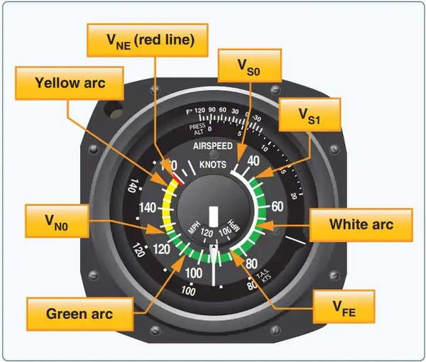
- The white band indicates the VS0 to VFE range.
- The green band indicates the VS1 - VNO range.
- The yellow band indicates the VNO - VNE range.
- Not every V-speed applies to every aircraft.
Va
Design maneuvering speed.
Vb
Design speed for maximum gust intensity.
Vbr
Best range speed.
Vbe
Best endurance speed.
Vc
Design cruise speed.
Vd
Designed dive speed.
Vdf/Mdf
Demonstrated flight diving speed.
Vef
The speed at which the critical engine is assumed to fail during takeoff.
Vf
Designed flap speed.
Vfc/Mfc
Maximum speed for stability characteristics.
Vfe
Maximum flaps extended (top of white arc).
Vfto
Maximum final takeoff speed.
Vh
Maximum speed in level flight with maximum continuous power.
Vle
Maximum speed at which an aircraft can be safely flown with the landing gear extended.
Vlo
Maximum landing-gear operating speed.
Vlof
Lift-off speed.
Vmca
Minimum controllable airspeed with the critical engine inoperative (red line).
Vmcg
Minimum control speed with critical engine out for takeoff run.
Vmo/Mmo
Maximum operating limit speed.
VMU
Minimum un-stick speed (all engines).
Vmu
Minimum un-stick speed (single-engine).
Vne
Never-exceed speed (red line).
Vno
Maximum cruise speed (top of green arc).
Vr
Rotation speed.
Vref
Reference speed for landing speed (1.3 Vso), when none provide in POH.
Vs
Stalling speed or the minimum steady flight speed at which the airplane is controllable.
Vs0
Stalling speed or the minimum steady flight speed in a landing configuration.
Vs1
Stalling speed or the minimum steady flight speed obtained in a specific configuration (same as Vs).
Vsse
Minimum safe single-engine speed.
Vsr
Reference stalling speed.
Vsr0
Reference stalling speed in the landing configuration.
Vsr1
Reference stalling speed in a specific configuration.
Vsw
Speed at which onset of natural or artificial stall warning occurs.
Vtoss
Take off steady speed for Category A rotor-craft.
Vx
Best angle-of-climb, providing the greatest amount of altitude in a given distance (short-field takeoffs).
Vxse
Best single-engine angle-of-climb speed.
Vy
Best rate-of-climb speed, providing the most altitude gain in a given period of time.
Vyse
Best single-engine rate-of-climb speed.
V1
Maximum speed in the takeoff at which the pilot must take the first action to stop the airplane within the accelerate-stop distance. Also means the minimum speed in the takeoff, following a failure of the critical engine at Vef, at which the pilot can continue the takeoff and achieve the required height above the takeoff surface within the takeoff distance.
V2
Takeoff safety speed.
V2min
Minimum takeoff safety speed.
Minimum go:
Airspeed required with loss of engine to get safely airborne.
-
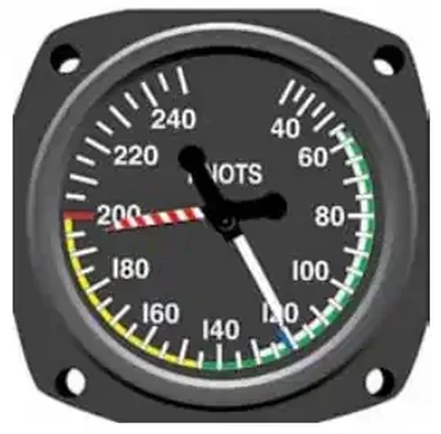
Maximum Allowable Airspeed:
- An aneroid or altimeter mechanism actuates the maximum airspeed pointer that moves it to a lower value as air density decreases. []
- This instrument looks much like a standard air-speed indicator, calibrated in knots, but has an additional pointer colored red, checkered, or striped.
- Some aircraft use true ASIs with temperature-compensated aneroid bellows inside the instrument case.
- These bellows modify the movement of the rocking shaft inside the instrument case so the pointer shows the actual TAS.
- These instruments have the conventional airspeed mechanism, with an added sub-dial visible through cutouts in the regular dial.
- A knob on the instrument allows the pilot to rotate the sub-dial and align an indication of the outside air temperature with the pressure altitude flown.
- This alignment causes the instrument pointer to indicate the TAS on the sub-dial.
-
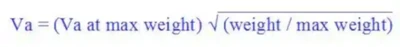
Maneuvering Speed:
- Va is the maximum speed at which abrupt application of full control deflection without over-stressing the aircraft and depends on the aircraft's weight. []
- As learned from American Airlines 587 (crash in Queens, post 9/11), abrupt changes in the controls repeatedly negate Va, and you may cause structural failure.
- Formula:
- Not every airspeed will have an indication marked on the airspeed indicator such as Va or Vle.


Types of Airspeeds
- Pilots reference many types of airspeeds for different purposes, such as performance or navigation planning. []
- Types of airspeeds include:
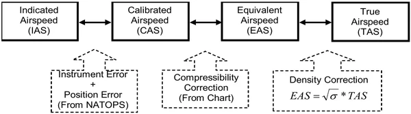
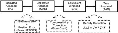
- Indicated Airspeed (IAS): the direct airspeed reading shown by an airspeed indicator.
- Calibrated Airspeed (CAS): the indicated airspeed of an aircraft, corrected for position and instrument error.
- Equivalent Airspeed (EAS): calibrated airspeed corrected for compressibility effects.
- True Airspeed (TAS): CAS corrected for non-standard temperature with the help of an Outside Air Temperature (OAT) gauge and altitude.
- Ground speed (GS): the actual speed of the airplane over the ground and is an important performance number for flight planning.
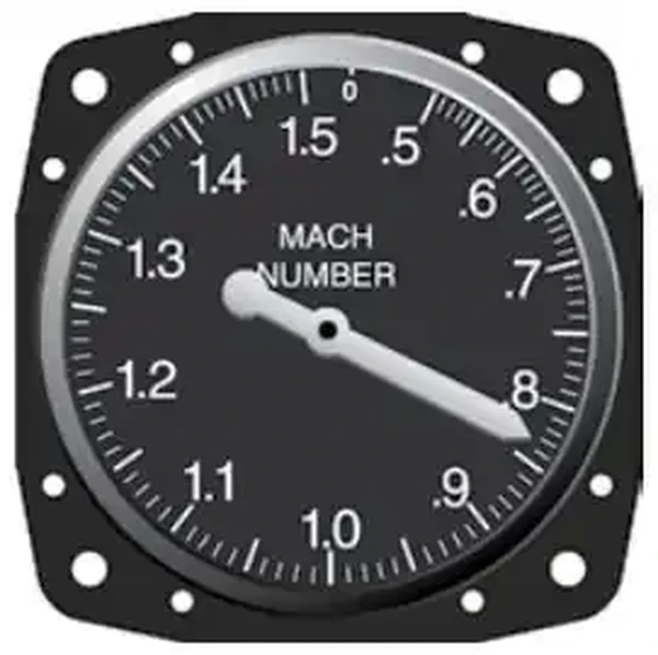
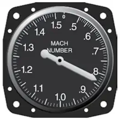
- Mach number: the ratio of the TAS of the aircraft to the speed of sound in the same atmospheric conditions.
-
Indicated Airspeed:
- Indicated Airspeed (IAS) is the direct airspeed reading shown by an airspeed indicator.
- The reading does not correct for atmospheric density variations, installation, or instrument errors.
- As height increases, the indicated airspeed falls below the true airspeed.
- Manufacturers use this airspeed as the basis for determining aircraft performance.
- IAS will not normally vary with altitude or temperature, so your V-speeds listed in the AFM/POH will mainly vary due to weight.
-
Calibrated Airspeed:
- Calibrated Airspeed (CAS) is the indicated airspeed of an aircraft, corrected for position and instrument error.
- Errors can include angle of attack, flap configuration, ground proximity, and wind direction, to name a few.
- Errors can sometimes equal several knots and are generally greatest at low airspeeds.
- Any errors that interfere with the system reading total and static pressure (which, when subtracted, give you dynamic pressure) are corrected here.
- This will give the actual speed at which the aircraft moves through the air.
- Calibrated airspeed is equal to true airspeed in standard atmosphere at sea level (High AOA, minimal error at cruise).
- The POH/AFM has a chart or graph to correct IAS for these errors and provide the correct CAS for the various flap and landing gear configurations. []
- Some aircraft have alternate static sources, often contained in a separate chart.
- Calibrated Airspeed (CAS) is the indicated airspeed of an aircraft, corrected for position and instrument error.
-
Equivalent Airspeed:
- Equivalent Airspeed (EAS) is calibrated airspeed corrected for compressibility effects above 180-200 knots and 20,000', the airspeed the airplane "feels."
- EAS is not usually practical for pilots and is more used by engineers to determine performance.
- As the airspeed and pressure altitude increase, the CAS becomes higher than it should be as air molecules begin to stack up against the aircraft and instruments.
- A correction for compression must be subtracted from the CAS.
-
True Airspeed:
- True Airspeed (TAS) is CAS corrected for non-standard temperature with the help of an Outside Air Temperature (OAT) gauge and altitude.
- The TAS is the speed used for planning and filing a flight plan.
- True airspeed varies directly with temperature.
- True airspeed increases with increased temperatures.
- True airpseed decreases with decreased temperatures.
- Since temperature impacts density altitude, true airspeed also varies directly with density altitude.
- True airspeed increases with increased density altitude.
- True airspeed decreases with decreased density altitude.
-
Calculating True Airspeed:
-
Flight Computer Method:
- The most accurate method is to use a flight computer.
- This method applies temperature and pressure corrections using the computer's airspeed correction scale.
- Extremely accurate electronic flight computers are also available.
- Just enter the CAS, pressure altitude, and temperature, and the computer calculates the TAS.
-
Rule of Thumb:
- A second method, a rule of thumb, provides the approximate TAS.
- Add 2 percent to the CAS for each 1,000 feet of altitude.
Formula:
- 5 (5000 ft) * 0.02 = .1 (correction factor).
- .1 * 100 KCAS (cruise airspeed) = 10 knots (correction speed).
- 100 (CAS) + 10 = 110 knots TAS.
-
- True Airspeed (TAS) is CAS corrected for non-standard temperature with the help of an Outside Air Temperature (OAT) gauge and altitude.
-
Ground Speed:
- Ground speed (GS) is the actual speed of the airplane over the ground and is an important performance number for flight planning.
- Groundspeed is TAS adjusted for wind (airmass movement).
- GS decreases with a headwind and increases with a tailwind.
- In more extreme examples, groundspeed is zero in a straight dive or straight climb despite an airspeed indicator showing rapid acceleration/deceleration.
- Therefore, groundspeed can be the same as (still air) TAS or drastically different (heavy winds, extreme pitch angles) from what is indicated on an airspeed indicator.
-
Calculating Groundspeed:
- Calculating ground speed can be done through complex mathematical equations, but it's more practically done by subtracting headwinds from the TAS and adding tailwinds.
-
Mach Number:
- Mach number is the ratio of the TAS of the aircraft to the speed of sound in the same atmospheric conditions. []
- Some older mechanical Machmeters not driven from an air data computer use an altitude aneroid inside the instrument that converts pitot-static pressure into Mach number.
- Modern electronic Machmeters use information from an air data computer system to correct for temperature errors to display true Mach number.

Airspeed Indicator Preflight Actions
- The airspeed indicator should read straight up and down unless a significant wind (enough for the aircraft to sense) blows into the Pitot tube.
- Airspeed should "come alive" on takeoff roll, meaning the dial registers an increase.
- Airspeed increasing should be verbalized as "airspeed alive."
Inertial Reference Unit (IRU), Inertial Navigation System (INS), and Attitude Heading Reference System (AHRS)
- IRUs are self-contained systems comprised of gyros and accelerometers that provide aircraft attitude (pitch, roll, and heading), position, and velocity information in response to signals resulting from inertial effects on system components.
- Once aligned with a known position, IRUs continuously calculate position and velocity. IRU position accuracy decays with time.
- This degradation is known as "drift."
- INSs combine the components of an IRU with an internal navigation computer.
- By programming a series of waypoints, these systems will navigate along a predetermined track.
- AHRSs are electronic devices that provide attitude information to aircraft systems such as weather radar and autopilot, but do not directly compute position information.
- Aircraft equipped with slaved compass systems may be susceptible to heading errors caused by exposure to magnetic field disturbances (flux fields) found in materials that are commonly located on the surface or buried under taxiways and ramps.
- These materials generate a magnetic flux field that can be sensed by the aircraft's compass system flux detector or "gate", which can cause the aircraft's system to align with the material's magnetic field rather than the earth's natural magnetic field.
- The system's erroneous heading may not self-correct.
- Prior to take off pilots should be aware that a heading misalignment may have occurred during taxi.
- Pilots are encouraged to follow the manufacturer's or other appropriate procedures to correct possible heading misalignment before take off is commenced.
Airspeed Indicator Anomalies and Malfunctions
- The pitot-static systems in modern aircraft are reliable, that we are always taught to "believe our instruments.". []
- However, when they do fail, the failure may be so insidious that it goes unnoticed until it's too late.
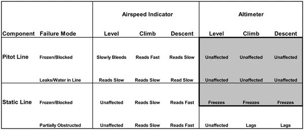
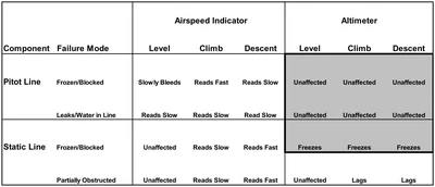
- Pitot-static failures typically come in three varieties:
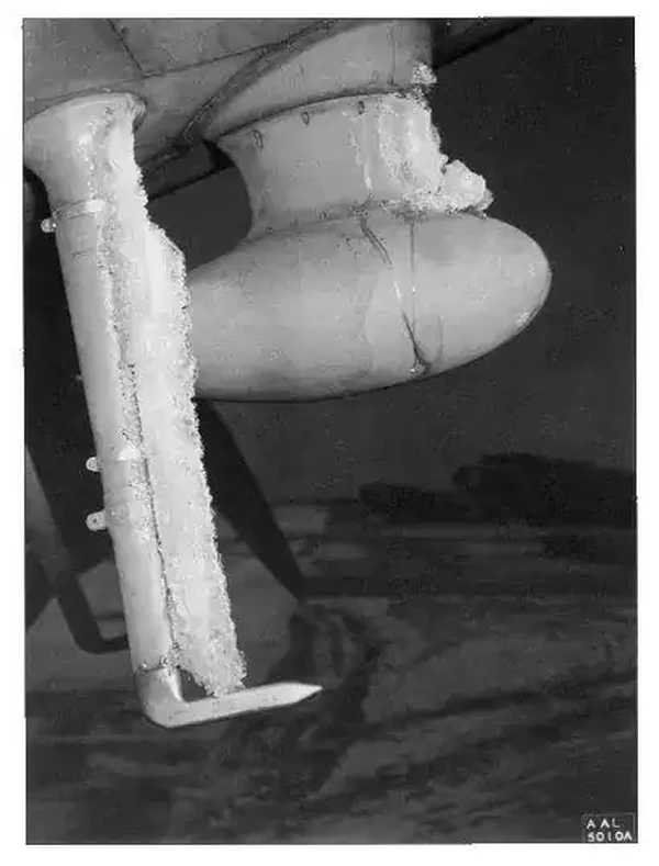
- Icing over the Pitot or static ports. []
- Trapped water in the lines (usually after maintenance fails to cover the ports during a wash).
- Compromise of system integrity:
- Leaks due to holes or loose fittings.
- Kinks in the lines.
- Obstructions/blockages.
- Taped or covered ports.
- Blockages in the system can cause a variety of errors.
- To prevent these errors, pilots must complete a thorough pre-flight.
- Blockages can occur from FOD, striking an object (damaging instruments), insects, trapped moisture, loss of system integrity, icing, etc.
- Pitot-Static system errors are generally the highest at low airspeed (high angles of attack)
- Position error may have a larger impact in certain configurations
-
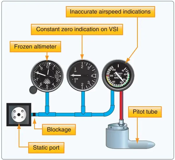
Pitot-Tube and Drain Hole Blockage (static open):
- The airspeed indicator will freeze and read like an altimeter as the total pressure now remains constant, and the static pressure changes with climbs and descents.
- The measure of ram air to static air means that as altitude increases and pressure decreases, the instrument will read artificially high compared to the same dynamic (ram) pressure.
- Likewise, if pressure increases, such as in a descent, it will read artificially low.
- The aircraft will only read the correct airspeed at the altitude where the blockage occurred, assuming that static pressure is not changing.
-
Static Blockage:
- If the static system becomes blocked but the pitot tube remains clear, the ASI continues to operate; however, it is inaccurate. []
- At the altitude where the blockage occurs, airspeed indications would be normal.
- The airspeed indicates lower than the actual airspeed when the aircraft is operated above the altitude where the static ports became blocked because the trapped static pressure is higher than normal for that altitude.
- When operating at a lower altitude, a faster than actual airspeed is displayed due to the relatively low static pressure trapped in the system.
- If the aircraft descends, the static pressure increases on the pitot side showing an increase on the ASI. This assumes that the aircraft does not actually increase its speed.
- The increase in static pressure on the pitot side is equivalent to an increase in dynamic pressure since the pressure cannot change on the static side.
- If an aircraft begins to climb after a static port becomes blocked, the airspeed begins to show a decrease as the aircraft continues to climb.
- This is due to the decrease in static pressure on the pitot side, while the pressure on the static side is held constant.
- Some aircraft are equipped with an alternate static source in the flight deck.
- In the case of a blocked static source, opening the alternate static source introduces static pressure from the flight deck into the system.
- Flight deck static pressure is lower than outside static pressure.
- Check the aircraft AFM/POH for airspeed corrections when utilizing alternate static pressure.
- A blockage of the static system also affects the altimeter and VSI, as well.
- Airspeed indicator failure demonstrates the importance of relating pitch attitudes to airspeeds.
- An additional tool would be ground-speed readings, like from a GPS, noting that groundspeed does not account for winds-aloft and therefore is not an accurate reading.
- Realize too, that errors in the indication can be induced by slipping the aircraft.


Common Training Aircraft Pitot-Static System Characteristics
-
Piper Arrow:
- Composed of a heated Pitot tube on the lower left wing
- Two static ports are located on each side of the fuselage
- Alternate static air (below the pilot control yoke) provides static pressure from inside the cabin
-
Cessna 172:
- Composed of a heated Pitot tube on the lower surface of the left wing
- An external static port is located on the lower left side of the forward fuselage
- Pitot Tube consists of a heating element, a 5-amp switch/breaker, and associated wiring
- Alternate static (below throttle) provides pressure from inside the cabin
Airspeed Indicator Lessons & Case Studies
- National Transportation Safety Board (NTSB) Identification: CEN20LA069:
- The NTSB determines the probable cause(s) of this accident to be: Water trapped in the static system, which resulted in incorrect airspeed display information and the pilot's forced landing.
Airspeed Indicator Knowledge Check
Private Pilot

Core Knowledge Review
Review the foundational knowledge, key concepts, and practical considerations for Airspeed Indicator.
Foundational
Immediate Feedback
Answer Explanations
Commercial Pilot

Advanced Application
Apply your knowledge of Airspeed Indicator to advanced operational scenarios, risk management, and aeronautical decision-making.
Advanced
Scenario Based
Risk Management
Why Take a Quiz?
Quizzes reinforce key concepts, identify knowledge gaps, and build confidence for real-world decisions in the cockpit.
Airspeed Indicator Conclusion
- The airspeed indicator is critically important for ensuring that structural speeds are not exceeded.
- Exceeding those limits may cause over-stress and damage to the aircraft.
- Always keep in mind the effects of parallax error.
- Beyond the direct indications from the instrument, think of what else it might be telling you such as Nautical Miles per hour.
- Since Knots = Nautical Miles per Hour, 60 knots (TAS, not IAS!) is 60 NM in an hour and a NM per minute.
- Airspeed indicator readings are all relative to the surrounding airmass.
- Note that while an approach or landing speed may be specified, the speeds held on approach will differ from final to round-out to flare.
- Consult the Pilot's Operating Handbook/Airplane Flight Manual (POH/AFM) to determine the amount of error.
- Still looking for something? Continue searching:
Airspeed Indicator References
- Federal Aviation Administration - Pilot/Controller Glossary.
- Aeronautical Information Manual (1-1-15) Inertial Reference Unit (IRU), Inertial Navigation System (INS), and Attitude Heading Reference System (AHRS).
- Bold Method - What's The Difference Between Approach Speed And Threshold Crossing Speed?.
- CFI Notebook.net - Performance Calculations.
- CFI Notebook.net - Pitot Static System.
- Federal Aviation Regulations (91.205) Powered civil aircraft with standard category U.S. airworthiness certificates: Instrument and equipment requirements.
- Federal Aviation Regulations (91.411) Altimeter system and altitude reporting equipment tests and inspections.
- Instrument Flying Handbook (3-8) Airspeed Indicator (ASI).
- NASA - Pitot-Static Tube.
- Smart Cockpit.com - Getting to Grips with Aircraft Performance.