Vertical Speed Indicator
The Vertical Speed Indicator (VSI) is an instrument that displays the rate of climb and descent to the pilot.
Introduction to Vertical Speed Indicator
- The Vertical Speed Indicator (VSI) is an instrument that displays the rate of climb and descent to the pilot by measuring rate-of-pressure changes.
- Pressure changes provide vertical speed indications for the pilot to determine the aircraft's trend before the altimeter registers changes.
- While not required to function or be calibrated for flight, the vertical speed indicator does contain inherent errors for pilots to consider as part of their preflight actions.
- Newer aircraft utilize modern Inertial Reference Unit (IRU), Inertial Navigation System (INS), and Attitude Heading Reference System (AHRS) systems for glass displays.
- As with any system or instrument, anomalies and malfunctions are possible, requiring detailed knowledge of the indicator and related systems.
Vertical Speed Indicator Key Highlights
- The vertical speed indicator (VSI) displays the rate at which an aircraft is climbing or descending.
- The VSI measures changes in static air pressure to calculate vertical speed in feet per minute.
- Positive indications show climbs, while negative indications show descents relative to the aircraft’s current altitude trend.
- The instrument contains a calibrated leak that allows pressure changes to be measured over time.
- Vertical speed indicators help pilots establish and maintain precise climb and descent rates during flight operations.
- The VSI is especially useful during instrument flight, altitude changes, and stabilized approach procedures.
- Traditional VSIs have a slight lag in response because they rely on gradual pressure equalization.
- Instantaneous vertical speed indicators (IVSIs) reduce lag and provide faster vertical trend information.
- Pilots should cross-check VSI indications with the altimeter, attitude indicator, and airspeed indicator during altitude changes.
- Understanding vertical speed indicator operation improves altitude control, instrument proficiency, and overall flight safety.
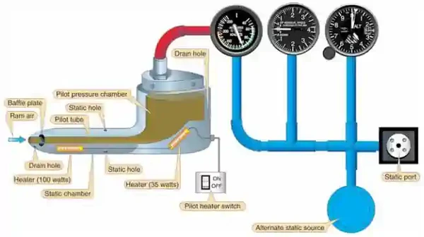
Pitot-Static System
- Pitot Static systems measure and compare air pressures from the Pitot tube and static port
- These measurements display indications for the Airspeed Indicator (ASI), Altimeter, and Vertical Speed Indicators (VSI).
- The system consists of two components:
-
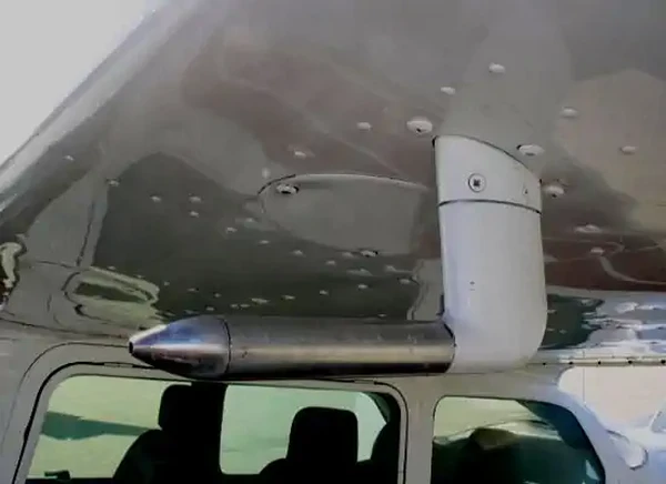
Pitot Tube:
- Invented by Henri Pitot in 1732, the Pitot tube measures fluid flow (air) velocity.
- The device measures ram (forced) air through a small hole in its front.
- The device's placement is often on the front of the aircraft or an airfoil to capture smooth (undisturbed) air. []
- The ram air captured produces an airspeed reading on the airspeed indicator (ASI).
-
Pitot Heat:
- Pitot Tubes are often electrically heated, which can prevent and remove ice accumulation. []
- Note that these devices should only be utilized during ground operations when necessary.
- Leaving them on unnecessarily can cause heat to the point of damage/malfunction.
- When airborne, the airflow otherwise cools the device.
-
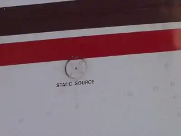
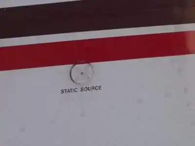
Static Port:
- Static ports measure ambient still-air atmospheric pressure.
- Typically, ports are flush mounted on the side of the aircraft where air is undisturbed. []
- Some aircraft may utilize heated static ports to mitigate ice.
- Dual ports remove errors due to slips and skids.
- Responsible for Airspeed Indicator, Altimeter, and Vertical Speed Indicators.
- The POH/AFM contains any corrections to the airspeed for the various flaps and landing gear configurations.
-
Alternate Static Source:
- An alternate static air source valve is available for emergencies on some aircraft.
- If the alternate source ports inside the airplane, where static pressure is usually lower than outside, selection may result in the following erroneous instrument indications:
- The altimeter reads higher than normal.
- Indicated airspeed (IAS) reads greater than normal.
- VSI momentarily shows a climb.
- Many POHs provide a correction table and aircraft-specific instructions.
- The alternate static source is not corrected for non-standard pressure (as with an altimeter's Kollsman window).
- Using alternate static sources may impact other instruments that rely on static pressure (i.e., autopilots, TCAS, transponder, etc.).
- Using alternate static sources can also decrease the accuracy beyond the 75 feet recommendation outlined in the Aeronautical Information Manual.


Vertical Speed Indicator Design and Function
- Vertical Speed Indicator (VSIs) measure rate-of-pressure change to provide a rate of climb or descent indication. []
- Air is provided through the static ports where it enters a diaphragm (aneroid).
- The diaphragm expands/retracts to indicate a climb/descent by measuring the ambient changes in pressure within the static system.
- As pressure drops, the aneroid compresses, indicating a climb
- As the pressure increases, the aneroid expands, indicating a descent
- Through a calibrated leak/orifice, the air leaves the instrument case slower than the aneroid and allows for a stabilized indication of pressure change on the face of the instrument.
- As the aircraft levels off, pressure no longer changes and the pointer returns to its zero position
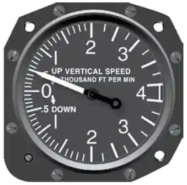
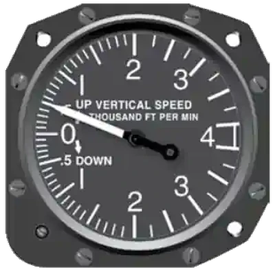
Vertical Speed Indications
- Vertical speed indicator start with a "0" indication at the 90 degree position and have notches to indicate the rate of climb both up and down that circle the dial
- Indicators may be calibrated differently depending on the country and its specified indication, which can be:
- Feet Per Minute (FPM)
- Meters Per Second (MPS)
- Nautical Miles Per Hour (Knots)
Vertical Speed Indicator Regulations
- There are no regulations that require a vertical speed indicator by federal aviation regulations.
- The vertical speed indicator is not required to meet a calibration standard or even be functional for flight to be legal.
- Always check the Pilot Operating Handbook to learn the specifics of it's operation.
Instrument Errors
- The vertical speed indicator inherently lags, but is more sensitive than an altimeter.
- This lag can result in a 6-9 second lag to stabilize which will inhibit accurate readings during turbulence or abrupt control movements.
- Instantaneous VSIs (IVSIs) use two accelerometer actuated pumps to give you a lag free indication
- Alternate sources of static, when selected, will typically show a momentary climb.
- This is due to pressure differences in the cockpit than outside.
- A blocked static port will give a zero indication.
Vertical Speed Indicator Preflight Actions
- If it indicates anything other than a zero feet per minute climb or descent on the ground, then the instrument can still be used, but that indication is the new "zero."
- This, of course, is highly discouraged if the error is such that a mistake could create a serious hazard to flight, especially in weather.
Vertical Speed Indicator Anomalies and Malfunctions
- Pitot-Static system errors are generally the highest at low airspeed (high angles of attack)
-
Static Port Blockage:
- If in a real emergency, malfunctions can be corrected with alternate air or breaking the glass on a Pitot static instrument (VSI).
- The trapped pressure in the static system causes the altimeter to remain at the altitude where the blockage occurred.
- The VSI remains at zero.
Private Pilot (Airplane) Operation of Aircraft Systems Airman Certification Standards
- Objective: To determine whether the applicant exhibits satisfactory knowledge, risk management, and skills associated with safe operation of systems on the airplane provided for the flight test.
- References: FAA-H-8083-2 (Risk Management Handbook), FAA-H-8083-3 (Airplane Flying Handbook), FAA-H-8083-23 (Seaplane, Skiplane, and Float/Ski Equipped Helicopter Operations Handbook), FAA-H-8083-25 (Pilot Handbook of Aeronautical Knowledge); POH/AFM.
- Note: If K1 is selected, the evaluator must assess the applicant's knowledge of at least three sub-elements
- Private Pilot Operation of Aircraft Systems Lesson Plan.
Private Pilot (Airplane) Operation of Aircraft Systems Knowledge:
The applicant demonstrates an understanding of:-
PA.I.G.K1:
Airplane systems, including:-
PA.I.G.K1a:
Primary flight controls. -
PA.I.G.K1a:
Secondary flight controls. -
PA.I.G.K1c:
Powerplant and propeller. -
PA.I.G.K1d:
Landing gear. -
PA.I.G.K1e:
Fuel, oil, and hydraulic. -
PA.I.G.K1f:
Electrical. -
PA.I.G.K1g:
Avionics. -
PA.I.G.K1h:
Pitot-static, vacuum/pressure, and associated flight instruments. -
PA.I.G.K1i:
Environmental. -
PA.I.G.K1j:
Deicing and anti-icing. -
PA.I.G.K1k:
Water Rudders (ASES, AMES). -
PA.I.G.K1l:
Oxygen Systems.
-
-
PA.I.G.K2:
Indications of and procedures for managing system abnormalities or failures.
Private Pilot (Airplane) Operation of Aircraft Systems Risk Management:
The applicant is able to identify, assess, and mitigate risks associated with:-
PA.I.G.R1:
Detection of system malfunctions or failures. -
PA.I.G.R2:
Management of a system failure. -
PA.I.G.R3:
Monitoring and management of automated systems.
Private Pilot (Airplane) Operation of Aircraft Systems Skills:
The applicant exhibits the skills to:-
PA.I.G.S1:
Operate at least three of the systems listed in K1a through K1l appropriately. -
PA.I.G.S2:
Complete the appropriate checklist(s).
Private Pilot (Airplane) Systems and Equipment Malfunctions Airman Certification Standards
- Objective: To determine whether the applicant exhibits satisfactory knowledge, risk management, and skills associated with system and equipment malfunctions appropriate to the airplane provided for the practical test
- References: FAA-H-8083-2 (Risk Management Handbook), FAA-H-8083-3 (Airplane Flying Handbook), FAA-H-8083-25 (Pilot Handbook of Aeronautical Knowledge); POH/AFM.
- Private Pilot (Airplane) Systems and Equipment Malfunctions Lesson Plan.
Private Pilot (Airplane) Systems and Equipment Malfunctions Knowledge:
The applicant demonstrates an understanding of:-
PA.IX.C.K1:
Causes of partial or complete power loss related to the specific type of powerplant(s).-
PA.IX.C.K1a:
[Archived]. -
PA.IX.C.K1b:
[Archived]. -
PA.IX.C.K1c:
[Archived]. -
PA.IX.C.K1d:
[Archived].
-
-
PA.IX.C.K2:
System and equipment malfunctions specific to the aircraft, including:-
PA.IX.C.K2a:
Electrical malfunction. -
PA.IX.C.K2b:
Vacuum/pressure and associated flight instrument malfunctions. -
PA.IX.C.K2c:
Pitot/static system malfunction. -
PA.IX.C.K2d:
Electronic flight deck display malfunction. -
PA.IX.C.K2e:
Landing gear or flap malfunction. -
PA.IX.C.K2f:
Inoperative trim.
-
-
PA.IX.C.K3:
Causes and remedies for smoke or fire onboard the aircraft. -
PA.IX.C.K4:
Any other system specific to the airplane (e.g., supplemental oxygen, deicing). -
PA.IX.C.K5:
Inadvertent door or window opening.
Private Pilot (Airplane) Systems and Equipment Malfunctions Risk Management:
The applicant is able to identify, assess, and mitigate risks associated with:-
PA.IX.C.R1:
Checklist usage for a system or equipment malfunction. -
PA.IX.C.R2:
Distractions, task prioritization, loss of situational awareness, or disorientation. -
PA.IX.C.R3:
Undesired aircraft state. -
PA.IX.C.R4:
Startle response.
Private Pilot (Airplane) Systems and Equipment Malfunctions Skills:
The applicant exhibits the skills to:-
PA.IX.C.S1:
Describe appropriate action for simulated emergencies specified by the evaluator, from at least three of the elements or sub-elements listed in K1 through K5 above. -
PA.IX.C.S2:
Complete the appropriate checklist(s).
Common Training Aircraft Pitot-Static System Characteristics
-
Piper Arrow:
- Composed of a heated Pitot tube on the lower left wing
- Two static ports are located on each side of the fuselage
- Alternate static air (below the pilot control yoke) provides static pressure from inside the cabin
-
Cessna 172:
- Composed of a heated Pitot tube on the lower surface of the left wing
- An external static port is located on the lower left side of the forward fuselage
- Pitot Tube consists of a heating element, a 5-amp switch/breaker, and associated wiring
- Alternate static (below throttle) provides pressure from inside the cabin
Vertical Speed Indicator Knowledge Check


Vertical Speed Indicator Conclusion
- The vertical speed indicator can go by many different names to include:
- Variometer
- Rate of Climb Indicator
- Vertical Velocity Indicator
- Vertical Speed Indicator (VSI) is however, most common
- Always keep in mind the effects of parallax error.
- Still looking for something? Continue searching:
Vertical Speed Indicator References
- Federal Aviation Administration - Pilot/Controller Glossary.
- Aeronautical Information Manual (1-1-15) Inertial Reference Unit (IRU), Inertial Navigation System (INS), and Attitude Heading Reference System (AHRS).
- CFI Notebook.net - Pilot Information Handbook.
- CFI Notebook.net - Pitot Static System.
- Instrument Flying Handbook (3-8) Vertical Speed Indicator (VSI).