Non-Directional Radio Beacon (NDB)
Non-Directional Beacons (NDBs) provides 360-degree azimuth information in the form of radials expressed in the magnetic heading, used for navigation.
Introduction
- The Non-Directional Radio Beacon (NDB) is a low or medium frequency radio beacon transmits non-directional signals whereby the pilot of an aircraft properly equipped can determine bearings and "home" to the station
- The pilot, through the use of an Automatic Direction Finder, uses these signals in order to determine relative/magnetic bearing and therefore position
- The entire system consists of:
- Ground station
- ADF receiver
- Antenna:
- Loop Antenna (Magnetic Bearing from the airplane to the station)
- Sense Antenna (Directional Information)
- Bearing Indicator
- Ultimately, the Standard Service Volume dictates the reception limits of the NAVAID
Frequencies
- These facilities normally operate in a frequency band of 190 to 535 kilohertz (kHz)
- According to International Civil Aviation Organization (ICAO) Annex 10 the frequency range for NDBs is between 190 and 1750 kHz, and transmit a continuous carrier with either 400 or 1020 hertz (Hz) modulation
- The NDB frequency can sometimes bleed over to the AM Radio frequency band and likewise radios can bleed over onto the NDB frequency
NDB Function
- All radio beacons except the compass locators transmit a continuous three-letter identification in code except during voice transmissions
- NDB frequency and identification information is found on aeronautical charts and in the Chart Supplement U.S.
- The Morse codes are used to identify the NDB stations while the commercial broadcast stations are identified at random times by the station's announcer
- These signals can be used to either home or intercept and track a course for navigation
NDB Advantages
- Relatively simple and low cost
- Accuracy is suitable for navigation but subject to numerous limitations
- Not limited by line of sight which permits reception at low altitudes over great distances due to ground waves
Automatic Direction Finder Receivers
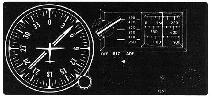
- Fixed Compass Card
- Movable (Rotating) Compass Card
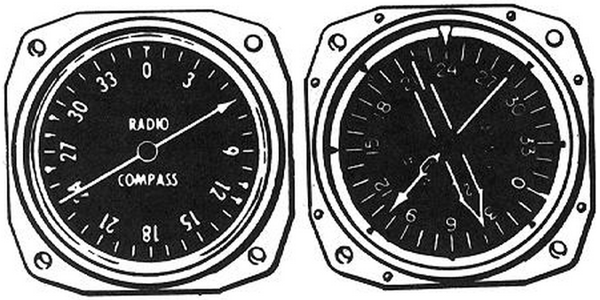
- Single-needled Radio Magnetic Indicator (RMI)
- Dual-needle Radio Magnetic Indicator (RMI)
-
Fixed Compass Card:
- A fixed compass card simply means the face of the instrument cannot rotate, leaving only the needles to move
- Always represent the nose of the aircraft at 0° and the tail as 180°
- Visualizing the situation with this type of indicator can be daunting
- RB + MH = MB
- (relative bearing) + (magnetic heading) = (magnetic bearing)
- Relative Bearing: Degrees flown to station (clockwise)
- Magnetic Heading: MH
- Magnetic Bearing: Distance from magnetic north
-
Movable Compass Card:
- Pilot can rotate the face of the card
- The ADF needle will directly indicate the magnetic bearing to the NDB when the aircraft heading is shown at the top
-
Single-Needle Radio Magnetic Indicator:
- Combines radio and magnetic information to provide continuous heading, bearing and radial information
-
Dual-Needle Radio Magnetic Indicator:
- Has a second needle
- The second needle typically points to a VOR station
NDB Applications
- Navigation
- "Colored" Airways (limited)
- Intercepting and tracking
- Holding
- Instrument Approaches
- Homing
- Tracking
Non-Directional Beacon Limitations
- Radio beacons are subject to disturbances that may result in erroneous bearing information
- Such disturbances result from factors such as lightning, precipitation static, etc.
- Nearly all disturbances which affect the Automatic Direction Finder (ADF) bearing also affect the facility's identification
- Noisy identification usually occurs when the ADF needle is erratic
- Voice, music or erroneous identification may be heard when a steady false bearing is being displayed
- Since ADF receivers do not have a "flag" to warn the pilot when erroneous bearing information is being displayed, the pilot should continuously monitor the NDB's identification
Twilight Error (Night Effect):
- Radio waves can be reflected back by the ionosphere and can cause fluctuations 30 to 60 NM (approx. 54 to 108 KM) from the transmitter, especially just before sunrise and just after sunset
Terrain Error:
- High terrain like hills and mountains can reflect radio waves, giving erroneous readings especially if they contain magnetic deposits
Electrical Error:
- Electrical storms, and sometimes also electrical interference can cause the ADF needle to deflect toward the electrical source
Shoreline Error:
- Low-frequency radio waves will refract or bend near a shoreline, especially if they are close to parallel to the shore
Bank Error:
- When the aircraft is banked, the needle reading will be offset
Standard Service Volume
- NDBs are classified according to their intended use [Figure 2]
- The distances (radius) are the same at all altitudes
NDB Bearing Tracking
- When necessary to follow a course directly to or from an NDB while making necessary corrections for wind:
- After the course has been intercepted, maintain the heading that corresponds to the Course To or Bearing From the station
- If a 10° course devision is indicated (off the nose of tail relative to the needle) then re-intercept by beginning with a change toward the "head" of the needle that is 20°
- Maintain the intercept heading until the angle of deflection from the nose or tail is 20° and then turn to a new course heading by taking out half of the intercept angle
- This new heading is the new relative bearing
- If the aDF needle deflects toward the nose or away from the tail, re-intercept by beginning with a 10° change in heading (intercept heading) toward the needle deflection
- Maintain the intercept heading until the deflection angle equals the intercept angle (deflection = correction), and then turn back to a new course heading by taking out half of the heading change
- Note that larger correction angles can be used if the wind requires
Conclusion
- Pilots should be aware of the possibility of momentary erroneous indications on cockpit displays when the primary signal generator for a ground-based navigational transmitter is inoperative
- Pilots should disregard any navigation indication, regardless of its apparent validity, if the particular transmitter was identified by NOTAM or otherwise as unusable or inoperative
- When a radio beacon is used in conjunction with the Instrument Landing System markers, it is called a Compass Locator
- Voice transmissions are made on radio beacons unless the letter "W" (without voice) is included in the class designator (HW)
- Do not include a flag to warn of inoperative conditions so signal must constantly be monitored
- Additionally tools are available to better increase your knowledge of navigation including VOR/NDB Simulators [Amazon]
- Remember, the FAA requests user reports on NAVAID outages
- Review your instrument approach safety knowledge by taking the Air Safety Institute's "A Day in the SUN" quiz
- Still looking for something? Continue searching:
References
- Federal Aviation Administration - Pilot/Controller Glossary
- Advisory Circular 61-21A - Flight Training Handbook (Chapter 12) ADF Navigation
- Aeronautical Information Manual (1-1-2) Non-directional Radio Beacon (NDB)
- Aeronautical Information Manual (1-1-8) NAVAID Service Volumes
- CFI Notebook.net - Notice to Air Missions (NOTAM)
- CFI Notebook.net - Chart Supplement U.S.
- Federal Aviation Regulations (91.177) Minimum Altitudes For IFR Operations
- Wikipedia - AM broadcasting


