Chart Supplement U.S.
Learn how pilots use the FAA Chart Supplement to find airport data, frequencies, runway details, operational remarks, legends, special notices, and preferred IFR routes.
Introduction to Chart Supplement U.S.
- The Chart Supplement U.S. (formerly the Airport/Facility Directory) is published every 56 days by the U.S. Department of Transportation, Federal Aviation Administration, National Aeronautical Charting Office
- It contains critical flight planning information
- Lists all airports, heliports, and seaplane bases which are open to the public
- Divided into 7 volumes, which cover the U.S., Puerto Rico, and the U.S. Virgin Islands
- Has a directory legend in front showing detailed explanation of a sample airport
- Test your understanding of Chart Supplement U.S. by completing the knowledge quiz, applying your knowledge in the interactive scenario, comparing your performance against the applicable Airman Certification Standards, and concluding with the topic summary to reinforce the key concepts before moving on to the next lesson.
Chart Supplement U.S. Key Highlights
- The Chart Supplement U.S. provides detailed airport, navigation, and operational information for pilots operating within the National Airspace System.
- The publication contains airport data, communication frequencies, runway information, lighting details, and operational remarks.
- Pilots use the Chart Supplement during preflight planning, arrivals, departures, and airport operations.
- Airport listings may include fuel availability, FBO services, traffic pattern information, customs facilities, and noise abatement procedures.
- Communication frequencies for ATIS (Automatic Terminal Information Service), tower, ground, CTAF (Common Traffic Advisory Frequency), UNICOM, and approach control services are commonly published.
- The Chart Supplement also contains information regarding parachute operations, special notices, preferred routes, and airport hazards.
- Pilots should verify current publication revisions because airport information and operational procedures change regularly.
- Electronic Flight Bags (EFBs) commonly integrate Chart Supplement data to improve operational efficiency and situational awareness.
- Failure to review airport remarks or operational limitations can increase workload and operational risk during flight operations.
- Understanding the Chart Supplement U.S. improves preflight planning, airport familiarity, and overall flight safety.
Chart Supplement U.S. Content
- The Chart Supplement, U.S., is broken into several sections: []
- General Information.
- Corrections, Comments and/or Procurement.
- Table of Contents
- Abbreviations
- Directory Legend
- Chart Supplement U.S.
- City/Military Airport Cross Reference
- Seaplane Landing Areas.
- Special Notices
- Regulatory Notices
- FAA and NWS (National Weather Service) Telephone numbers
- Air Route Traffic Control Centers/Flight Service Station Communication Frequencies.
- Flight Standards District Offices (FSDO).
- Preferred IFR Routes.
- VFR (Visual Flight Rules) waypoints
- VOR Receiver Check.
- Parachute Jumping Areas.
- Aeronautical Chart Bulletin
- Land and Hold Short Operations (LAHSO).
- Airport Diagrams - updates to aeronautical information

General Information
- The general information section of the Chart Supplement U.S. reads:
- This Chart Supplement U.S. is a Civil Flight Information Publication published and distributed every eight weeks by the U.S. Department of Transportation, Federal Aviation Administration, Aeronautical Information Services, https://www.faa.gov/go/ais. It is designed for use with Aeronautical Charts covering the conterminous United States, Puerto Rico and the Virgin Islands.
- This directory contains all public–use airports, seaplane bases and heliports, military facilities, and selected private use facilities specifically requested by the Department of Defense (DoD) for which a DoD Instrument Approach Procedure has been published in the U.S. Terminal Procedures Publication.
- Additionally, this directory contains communications data, navigational facilities and certain special notices and procedures.
- Military data contained within this publication is provided by the National Geospatial–Intelligence Agency and is intended to provide reference data for military and/or joint use airports. Not all military data contained in this publication is applicable to civil users.
Chart Supplement U.S. Corrections, Comments and/or Procurement
-
Corrections:
- Note: information such as equipment malfunction, abnormal field conditions, hazards to flight, etc., should be reported as soon as possible.
- FOR COMMENTS OR CORRECTIONS: https://www.faa.gov/air_traffic/flight_info/aeronav/aero_data/.
- FAA, Aeronautical Information Services.
- 1305 East West Highway.
- SSMC-4 Suite 4400.
- Silver Spring, MD 20910-3281.
- Telephone 1–800–638–8972.
- Deadlines for corrections to make the next publication are listed in the Chart Supplement.
-
Procurement:
- FOR PROCUREMENT:
- Contact an Authorized FAA Chart Sales Agent. Visit our website at https://www.faa.gov/go/ais and click on "Chart Agent Locator." For digital products, visit https://faacharts.faa.gov.
- This Chart Supplement U.S. comprises part of the following sections of the United States Aeronautical Information Publication (AIP): GEN, ENR and AD.
- FOR PROCUREMENT:
Chart Supplement U.S.
- This directory is a listing of data on record with the FAA on public–use airports, military airports and selected private–use airports specifically requested by the Department of Defense (DoD) for which a DoD Instrument Approach Procedure has been published in the U.S. Terminal Procedures Publication. Additionally this listing contains data for associated terminal control facilities, air route traffic control centers, and radio aids to navigation within the conterminous United States, Puerto Rico and the Virgin Islands. Civil airports and joint Civil/Military airports which are open to the public are listed alphabetically by state, associated city and airport name and cross–referenced by airport name. Military airports and private–use (limited civil access) joint Military/Civil airports are listed alphabetically by state and official airport name and cross–referenced by associated city name. Navaids, flight service stations and remote communication outlets that are associated with an airport, but with a different name, are listed alphabetically under their own name, as well as under the airport with which they are associated
- The listing of an airport as open to the public in this directory merely indicates the airport operator's willingness to accommodate transient aircraft, and does not represent that the airport conforms with any Federal or local standards, or that it has been approved for use on the part of the general public. Military airports, private–use airports, and private–use (limited civil access) joint Military/Civil airports are open to civil pilots only in an emergency or with prior permission. See Special Notice Section, Civil Use of Military Fields
- The information on obstructions is taken from reports submitted to the FAA. Obstruction data has not been verified in all cases. Pilots are cautioned that objects not indicated in this tabulation (or on the airports sketches and/or charts) may exist which can create a hazard to flight operation. Detailed specifics concerning services and facilities tabulated within this directory are contained in the Aeronautical Information Manual, Basic Flight Information and ATC Procedures
- The legend items that follow explain in detail the contents of this Directory and are keyed to the circled numbers on the sample on the preceding pages
Chart Supplement Airport Entry
Hover over or tap a numbered circle to learn what that part of the airport entry means.
FAA instructional sample from the Pacific edition, 3 September–29 October 2026. This is not current operational airport information. View the FAA source PDF (sample: printed page 10; legend: printed pages 12–28).
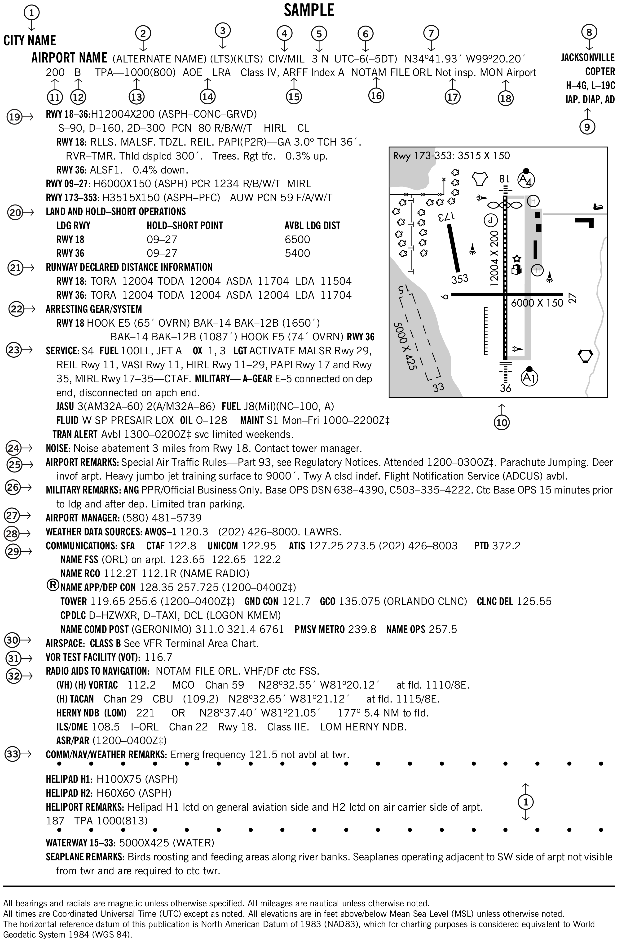
Read all 33 numbered explanations
The FAA legend text, subitems, and tables are reproduced below. Number 1 is used twice in the sample. The FAA’s original printed excerpts are also included with each explanation.
1. City/airport name
FAA Pacific edition, printed page 12. Transcribed from the source legend; the printed original is available below.
Civil and joint Civil/Military airports which are open to the public are listed alphabetically by state and associated city. Where the city name is different from the airport name the city name will appear on the line above the airport name. Airports with the same associated city name will be listed alphabetically by airport name and will be separated by a dashed rule line. A solid rule line will separate all others. FAA approved helipads and seaplane landing areas associated with a land airport will be separated by a dotted line. Military airports and private–use (limited civil access) joint Military/Civil airports are listed alphabetically by state and official airport name.
View the FAA printed original (including tables)

2. Alternate name
FAA Pacific edition, printed page 12. Transcribed from the source legend; the printed original is available below.
Alternate names, if any, will be shown in parentheses.
View the FAA printed original (including tables)

3. Location identifier
FAA Pacific edition, printed page 12. Transcribed from the source legend; the printed original is available below.
The location identifier is a three or four character FAA code followed by a four–character ICAO code, when assigned, to airports. If two different military codes are assigned, both codes will be shown with the primary operating agency’s code listed first. These identifiers are used by ATC in lieu of the airport name in flight plans, flight strips and other written records and computer operations. Zeros will appear with a slash to differentiate them from the letter ‘O’.
View the FAA printed original (including tables)

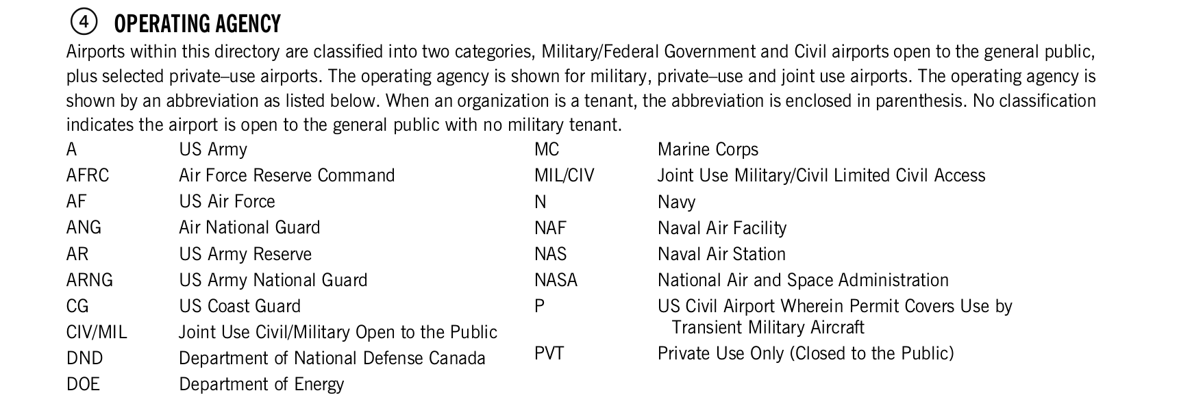
4. Operating agency
FAA Pacific edition, printed page 12. Transcribed from the source legend; the printed original is available below.
Airports within this directory are classified into two categories, Military/Federal Government and Civil airports open to the general public, plus selected private–use airports. The operating agency is shown for military, private–use and joint use airports. The operating agency is shown by an abbreviation as listed below. When an organization is a tenant, the abbreviation is enclosed in parenthesis. No classification indicates the airport is open to the general public with no military tenant.
| Code | Meaning |
|---|---|
| A | US Army |
| AFRC | Air Force Reserve Command |
| AF | US Air Force |
| ANG | Air National Guard |
| AR | US Army Reserve |
| ARNG | US Army National Guard |
| CG | US Coast Guard |
| CIV/MIL | Joint Use Civil/Military Open to the Public |
| DND | Department of National Defense Canada |
| DOE | Department of Energy |
| Code | Meaning |
|---|---|
| MC | Marine Corps |
| MIL/CIV | Joint Use Military/Civil Limited Civil Access |
| N | Navy |
| NAF | Naval Air Facility |
| NAS | Naval Air Station |
| NASA | National Air and Space Administration |
| P | US Civil Airport Wherein Permit Covers Use by Transient Military Aircraft |
| PVT | Private Use Only (Closed to the Public) |
View the FAA printed original (including tables)
5. Airport location
FAA Pacific edition, printed page 12. Transcribed from the source legend; the printed original is available below.
Airport location is expressed as distance and direction from the center of the associated city in nautical miles and cardinal points, e.g., 3 N.
View the FAA printed original (including tables)

6. Time conversion
FAA Pacific edition, printed page 12–13. Transcribed from the source legend; the printed original is available below.
Hours of operation of all facilities are expressed in Coordinated Universal Time (UTC) and shown as ‘Z’ time. The directory indicates the number of hours to be subtracted from UTC to obtain local standard time and local daylight saving time UTC–5(–4DT). The symbol ‡ indicates that during periods of Daylight Saving Time (DST) effective hours will be one hour earlier than shown. In those areas where daylight saving time is not observed the (–4DT) and ‡ will not be shown. Daylight saving time is in effect from 0200 local time the second Sunday in March to 0200 local time the first Sunday in November. Canada and all U.S. Conterminous States observe daylight saving time except Arizona and Puerto Rico, and the Virgin Islands. If the state observes daylight saving time and the operating times are other than daylight saving times, the operating hours will include the dates, times and no ‡ symbol will be shown, i.e., April 15–Aug 31 0630–1700Z, Sep 1–Apr 14 0600–1700Z.
View the FAA printed original (including tables)

7. Geographic position / airport reference point
FAA Pacific edition, printed page 13. Transcribed from the source legend; the printed original is available below.
GEOGRAPHIC POSITION OF AIRPORT—AIRPORT REFERENCE POINT (ARP)
Positions are shown as hemisphere, degrees, minutes and hundredths of a minute and represent the approximate geometric center of all usable runway surfaces.
View the FAA printed original (including tables)

8. Charts
FAA Pacific edition, printed page 13. Transcribed from the source legend; the printed original is available below.
Charts refer to the Sectional Chart and Low and High Altitude Enroute Chart and panel on which the airport or facility is depicted. Pacific Enroute Chart will be indicated by P. Area Enroute Charts will be indicated by A. Helicopter Chart depictions will be indicated as COPTER. IFR Gulf of America West and IFR Gulf of America Central will be referenced as GOAW and GOAC.
View the FAA printed original (including tables)

9. Instrument approach procedures and airport diagrams
FAA Pacific edition, printed page 13. Transcribed from the source legend; the printed original is available below.
INSTRUMENT APPROACH PROCEDURES, AIRPORT DIAGRAMS
IAP indicates an airport for which a prescribed (Public Use) FAA Instrument Approach Procedure has been published. DIAP indicates an airport for which a prescribed DoD Instrument Approach Procedure has been published in the U.S. Terminal Procedures. See the Special Notice Section of this directory, Civil Use of Military Fields and the Aeronautical Information Manual 5–4–5 Instrument Approach Procedure Charts for additional information. AD indicates an airport for which an airport diagram has been published. Airport diagrams are located in the back of each Chart Supplement volume alphabetically by associated city and airport name.
View the FAA printed original (including tables)

10. Airport sketch
FAA Pacific edition, printed page 13. Transcribed from the source legend; the printed original is available below.
The airport sketch, when provided, depicts the airport and related topographical information as seen from the air and should be used in conjunction with the text. It is intended as a guide for pilots in VFR conditions. Symbology that is not self–explanatory will be reflected in the sketch legend. The airport sketch will be oriented with True North at the top.
View the FAA printed original (including tables)

11. Elevation
FAA Pacific edition, printed page 13. Transcribed from the source legend; the printed original is available below.
The highest point of an airport's usable runways measured in feet from mean sea level. When elevation is sea level it will be indicated as ‘00’. When elevation is below sea level a minus ‘−’ sign will precede the figure.
View the FAA printed original (including tables)

12. Rotating light beacon
FAA Pacific edition, printed page 13. Transcribed from the source legend; the printed original is available below.
B indicates rotating beacon is available. Rotating beacons operate sunset to sunrise unless otherwise indicated in the AIRPORT REMARKS or MILITARY REMARKS segment of the airport entry.
View the FAA printed original (including tables)

13. Traffic pattern altitude
FAA Pacific edition, printed page 13. Transcribed from the source legend; the printed original is available below.
Traffic Pattern Altitude (TPA)—The first figure shown is TPA above mean sea level. The second figure in parentheses is TPA above airport elevation. TPA will only be published if they differ from the recommended altitudes as described in the AIM, Traffic Patterns. Multiple TPA shall be shown as ‘TPA—See Remarks’ and detailed information shall be shown in the Airport or Military Remarks Section. Traffic pattern data for USAF bases, USN facilities, and U.S. Army airports (including those on which ACC or U.S. Army is a tenant) that deviate from standard pattern altitudes shall be shown in Military Remarks.
View the FAA printed original (including tables)

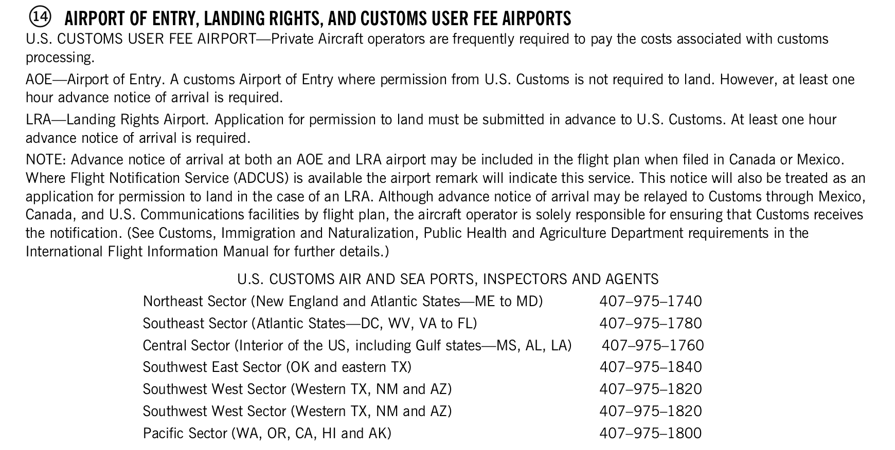
14. Airport of entry, landing rights and customs user fee airports
FAA Pacific edition, printed page 13–14. Transcribed from the source legend; the printed original is available below.
U.S. CUSTOMS USER FEE AIRPORT—Private Aircraft operators are frequently required to pay the costs associated with customs processing.
AOE—Airport of Entry. A customs Airport of Entry where permission from U.S. Customs is not required to land. However, at least one hour advance notice of arrival is required.
LRA—Landing Rights Airport. Application for permission to land must be submitted in advance to U.S. Customs. At least one hour advance notice of arrival is required.
NOTE: Advance notice of arrival at both an AOE and LRA airport may be included in the flight plan when filed in Canada or Mexico. Where Flight Notification Service (ADCUS) is available the airport remark will indicate this service. This notice will also be treated as an application for permission to land in the case of an LRA. Although advance notice of arrival may be relayed to Customs through Mexico, Canada, and U.S. Communications facilities by flight plan, the aircraft operator is solely responsible for ensuring that Customs receives the notification. (See Customs, Immigration and Naturalization, Public Health and Agriculture Department requirements in the International Flight Information Manual for further details.)
U.S. CUSTOMS AIR AND SEA PORTS, INSPECTORS AND AGENTS
| Sector | Telephone |
|---|---|
| Northeast Sector (New England and Atlantic States—ME to MD) | 407–975–1740 |
| Southeast Sector (Atlantic States—DC, WV, VA to FL) | 407–975–1780 |
| Central Sector (Interior of the US, including Gulf states—MS, AL, LA) | 407–975–1760 |
| Southwest East Sector (OK and eastern TX) | 407–975–1840 |
| Southwest West Sector (Western TX, NM and AZ) | 407–975–1820 |
| Southwest West Sector (Western TX, NM and AZ) | 407–975–1820 |
| Pacific Sector (WA, OR, CA, HI and AK) | 407–975–1800 |
View the FAA printed original (including tables)
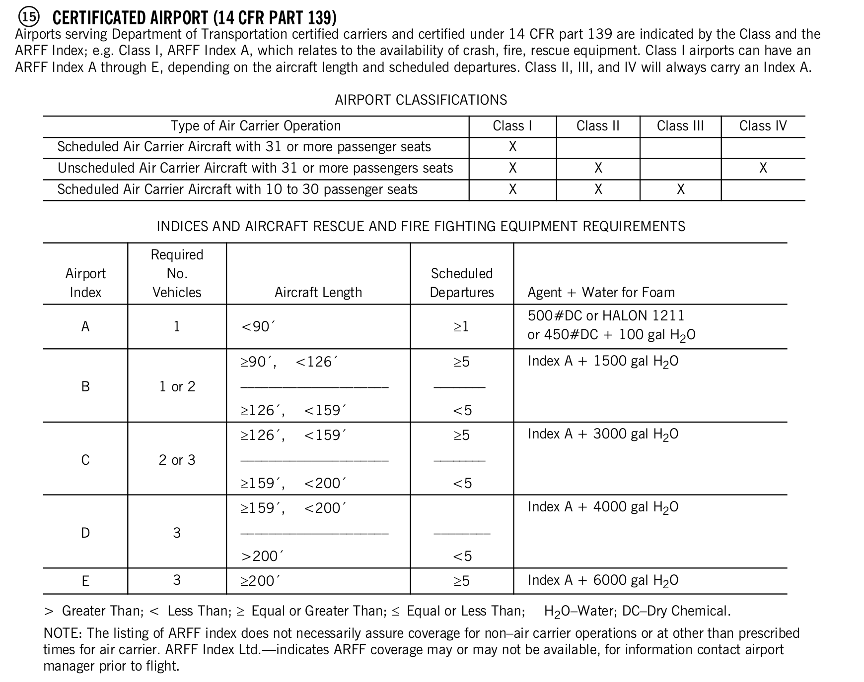
15. Certificated airport (14 CFR part 139)
FAA Pacific edition, printed page 14. Transcribed from the source legend; the printed original is available below.
Airports serving Department of Transportation certified carriers and certified under 14 CFR part 139 are indicated by the Class and the ARFF Index; e.g. Class I, ARFF Index A, which relates to the availability of crash, fire, rescue equipment. Class I airports can have an ARFF Index A through E, depending on the aircraft length and scheduled departures. Class II, III, and IV will always carry an Index A.
AIRPORT CLASSIFICATIONS
| Type of Air Carrier Operation | Class I | Class II | Class III | Class IV |
|---|---|---|---|---|
| Scheduled Air Carrier Aircraft with 31 or more passenger seats | X | |||
| Unscheduled Air Carrier Aircraft with 31 or more passengers seats | X | X | X | |
| Scheduled Air Carrier Aircraft with 10 to 30 passenger seats | X | X | X |
INDICES AND AIRCRAFT RESCUE AND FIRE FIGHTING EQUIPMENT REQUIREMENTS
| Airport Index | Required No. Vehicles | Aircraft Length | Scheduled Departures | Agent + Water for Foam |
|---|---|---|---|---|
| A | 1 | <90′ | ≥1 | 500#DC or HALON 1211 or 450#DC + 100 gal H2O |
| B | 1 or 2 | ≥90′, <126′ ––––––––––––––––––––– ≥126′, <159′ | ≥5 –––––––– <5 | Index A + 1500 gal H2O |
| C | 2 or 3 | ≥126′, <159′ ––––––––––––––––––––– ≥159′, <200′ | ≥5 –––––––– <5 | Index A + 3000 gal H2O |
| D | 3 | ≥159′, <200′ ––––––––––––––––––––– >200′ | –––––––– <5 | Index A + 4000 gal H2O |
| E | 3 | ≥200′ | ≥5 | Index A + 6000 gal H2O |
> Greater Than; < Less Than; ≥ Equal or Greater Than; ≤ Equal or Less Than;
H2O–Water; DC–Dry Chemical.
NOTE: The listing of ARFF index does not necessarily assure coverage for non–air carrier operations or at other than prescribed times for air carrier. ARFF Index Ltd.—indicates ARFF coverage may or may not be available, for information contact airport manager prior to flight.
View the FAA printed original (including tables)
16. NOTAM service
FAA Pacific edition, printed page 14. Transcribed from the source legend; the printed original is available below.
All public use landing areas are provided NOTAM service. A NOTAM FILE identifier is shown for individual landing areas, e.g., “NOTAM FILE BNA”. See the AIM, Basic Flight Information and ATC Procedures for a detailed description of NOTAMs. Current NOTAMs are available from flight service stations at 1–800–WX–BRIEF (992–7433) or online through the FAA PilotWeb at https:// pilotweb.nas.faa.gov. Military NOTAMs are available using the Defense Internet NOTAM Service (DINS) at https://www.notams.faa.gov. Pilots flying to or from airports not available through the FAA PilotWeb or DINS can obtain assistance from Flight Service.
View the FAA printed original (including tables)

17. FAA inspection
FAA Pacific edition, printed page 14. Transcribed from the source legend; the printed original is available below.
All airports not inspected by FAA will be identified by the note: Not insp. This indicates that the airport information has been provided by the owner or operator of the field.
View the FAA printed original (including tables)

18. Minimum operational network airport designation
FAA Pacific edition, printed page 14. Transcribed from the source legend; the printed original is available below.
MINIMUM OPERATIONAL NETWORK (MON) AIRPORT DESIGNATION
MON Airports have at least one VOR or ILS instrument approach procedure that can be flown without the need for GPS, WAAS, DME, NDB or RADAR. The primary purpose of the MON designation is for recovery in case of GPS outage.
View the FAA printed original (including tables)

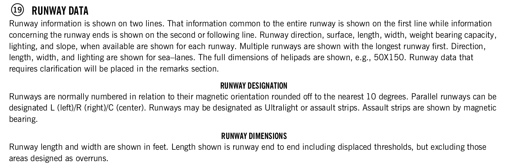
19. Runway data
FAA Pacific edition, printed page 14–17. Transcribed from the source legend; the printed original is available below.
Runway information is shown on two lines. That information common to the entire runway is shown on the first line while information concerning the runway ends is shown on the second or following line. Runway direction, surface, length, width, weight bearing capacity, lighting, and slope, when available are shown for each runway. Multiple runways are shown with the longest runway first. Direction, length, width, and lighting are shown for sea–lanes. The full dimensions of helipads are shown, e.g., 50X150. Runway data that requires clarification will be placed in the remarks section.
RUNWAY DESIGNATION
Runways are normally numbered in relation to their magnetic orientation rounded off to the nearest 10 degrees. Parallel runways can be designated L (left)/R (right)/C (center). Runways may be designated as Ultralight or assault strips. Assault strips are shown by magnetic bearing.
RUNWAY DIMENSIONS
Runway length and width are shown in feet. Length shown is runway end to end including displaced thresholds, but excluding those areas designed as overruns.
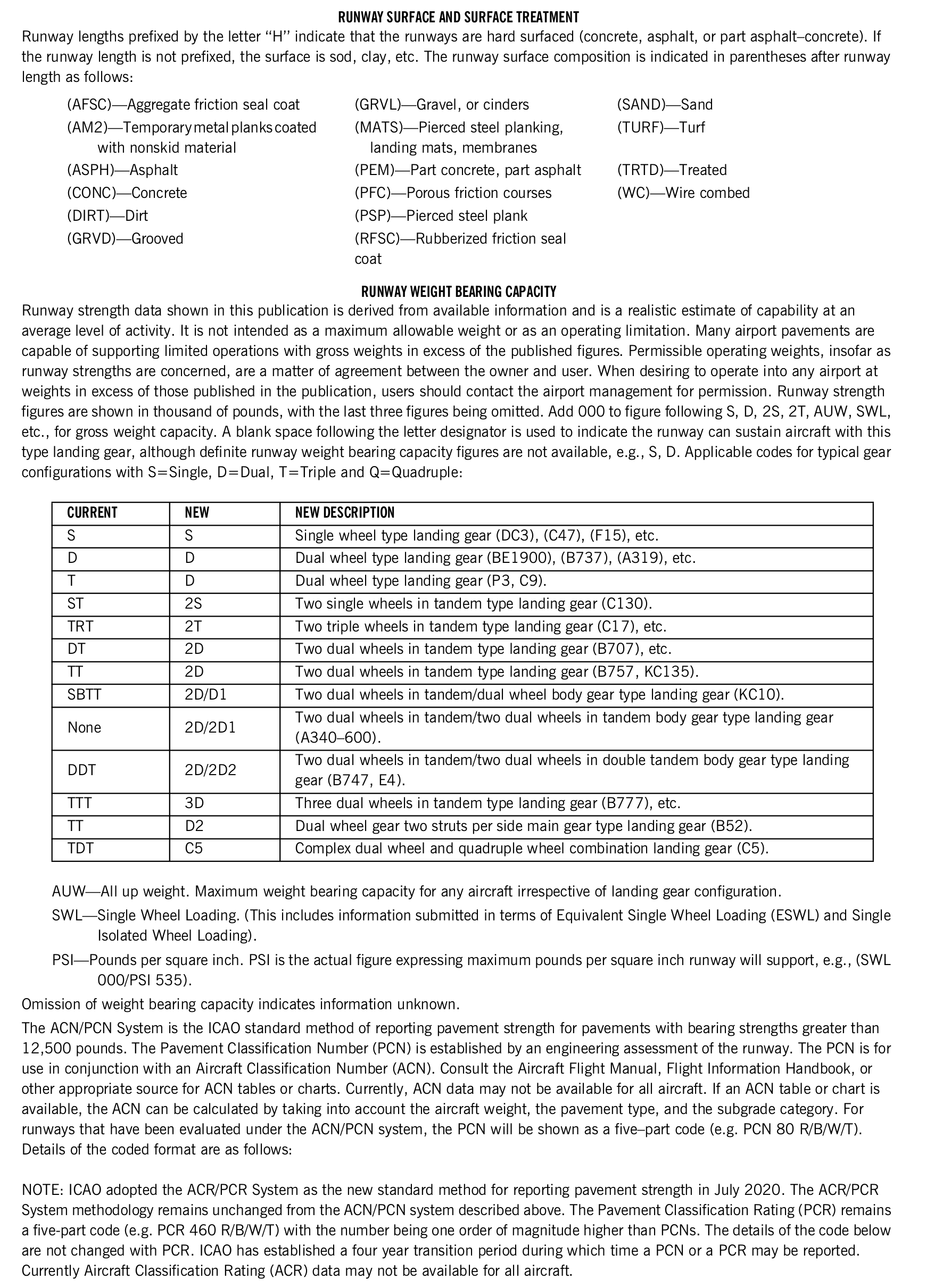
RUNWAY SURFACE AND SURFACE TREATMENT
Runway lengths prefixed by the letter “H” indicate that the runways are hard surfaced (concrete, asphalt, or part asphalt–concrete). If the runway length is not prefixed, the surface is sod, clay, etc. The runway surface composition is indicated in parentheses after runway length as follows:
- (AFSC)—Aggregate friction seal coat
- (AM2)—Temporary metal planks coated with nonskid material
- (ASPH)—Asphalt
- (CONC)—Concrete
- (DIRT)—Dirt
- (GRVD)—Grooved
- (GRVL)—Gravel, or cinders
- (MATS)—Pierced steel planking, landing mats, membranes
- (PEM)—Part concrete, part asphalt
- (PFC)—Porous friction courses
- (PSP)—Pierced steel plank
- (RFSC)—Rubberized friction seal coat
- (SAND)—Sand
- (TURF)—Turf
- (TRTD)—Treated
- (WC)—Wire combed
RUNWAY WEIGHT BEARING CAPACITY
Runway strength data shown in this publication is derived from available information and is a realistic estimate of capability at an average level of activity. It is not intended as a maximum allowable weight or as an operating limitation. Many airport pavements are capable of supporting limited operations with gross weights in excess of the published figures. Permissible operating weights, insofar as runway strengths are concerned, are a matter of agreement between the owner and user. When desiring to operate into any airport at weights in excess of those published in the publication, users should contact the airport management for permission. Runway strength figures are shown in thousand of pounds, with the last three figures being omitted. Add 000 to figure following S, D, 2S, 2T, AUW, SWL, etc., for gross weight capacity. A blank space following the letter designator is used to indicate the runway can sustain aircraft with this type landing gear, although definite runway weight bearing capacity figures are not available, e.g., S, D. Applicable codes for typical gear configurations with S=Single, D=Dual, T=Triple and Q=Quadruple:
| CURRENT | NEW | NEW DESCRIPTION |
|---|---|---|
| S | S | Single wheel type landing gear (DC3), (C47), (F15), etc. |
| D | D | Dual wheel type landing gear (BE1900), (B737), (A319), etc. |
| T | D | Dual wheel type landing gear (P3, C9). |
| ST | 2S | Two single wheels in tandem type landing gear (C130). |
| TRT | 2T | Two triple wheels in tandem type landing gear (C17), etc. |
| DT | 2D | Two dual wheels in tandem type landing gear (B707), etc. |
| TT | 2D | Two dual wheels in tandem type landing gear (B757, KC135). |
| SBTT | 2D/D1 | Two dual wheels in tandem/dual wheel body gear type landing gear (KC10). |
| None | 2D/2D1 | Two dual wheels in tandem/two dual wheels in tandem body gear type landing gear (A340–600). |
| DDT | 2D/2D2 | Two dual wheels in tandem/two dual wheels in double tandem body gear type landing gear (B747, E4). |
| TTT | 3D | Three dual wheels in tandem type landing gear (B777), etc. |
| TT | D2 | Dual wheel gear two struts per side main gear type landing gear (B52). |
| TDT | C5 | Complex dual wheel and quadruple wheel combination landing gear (C5). |
AUW—All up weight. Maximum weight bearing capacity for any aircraft irrespective of landing gear configuration.
SWL—Single Wheel Loading. (This includes information submitted in terms of Equivalent Single Wheel Loading (ESWL) and Single Isolated Wheel Loading).
PSI—Pounds per square inch. PSI is the actual figure expressing maximum pounds per square inch runway will support, e.g., (SWL 000/PSI 535).
Omission of weight bearing capacity indicates information unknown.
The ACN/PCN System is the ICAO standard method of reporting pavement strength for pavements with bearing strengths greater than 12,500 pounds. The Pavement Classification Number (PCN) is established by an engineering assessment of the runway. The PCN is for use in conjunction with an Aircraft Classification Number (ACN). Consult the Aircraft Flight Manual, Flight Information Handbook, or other appropriate source for ACN tables or charts. Currently, ACN data may not be available for all aircraft. If an ACN table or chart is available, the ACN can be calculated by taking into account the aircraft weight, the pavement type, and the subgrade category. For runways that have been evaluated under the ACN/PCN system, the PCN will be shown as a five–part code (e.g. PCN 80 R/B/W/T). Details of the coded format are as follows:
NOTE: ICAO adopted the ACR/PCR System as the new standard method for reporting pavement strength in July 2020. The ACR/PCR System methodology remains unchanged from the ACN/PCN system described above. The Pavement Classification Rating (PCR) remains a five-part code (e.g. PCR 460 R/B/W/T) with the number being one order of magnitude higher than PCNs. The details of the code below are not changed with PCR. ICAO has established a four year transition period during which time a PCN or a PCR may be reported. Currently Aircraft Classification Rating (ACR) data may not be available for all aircraft.
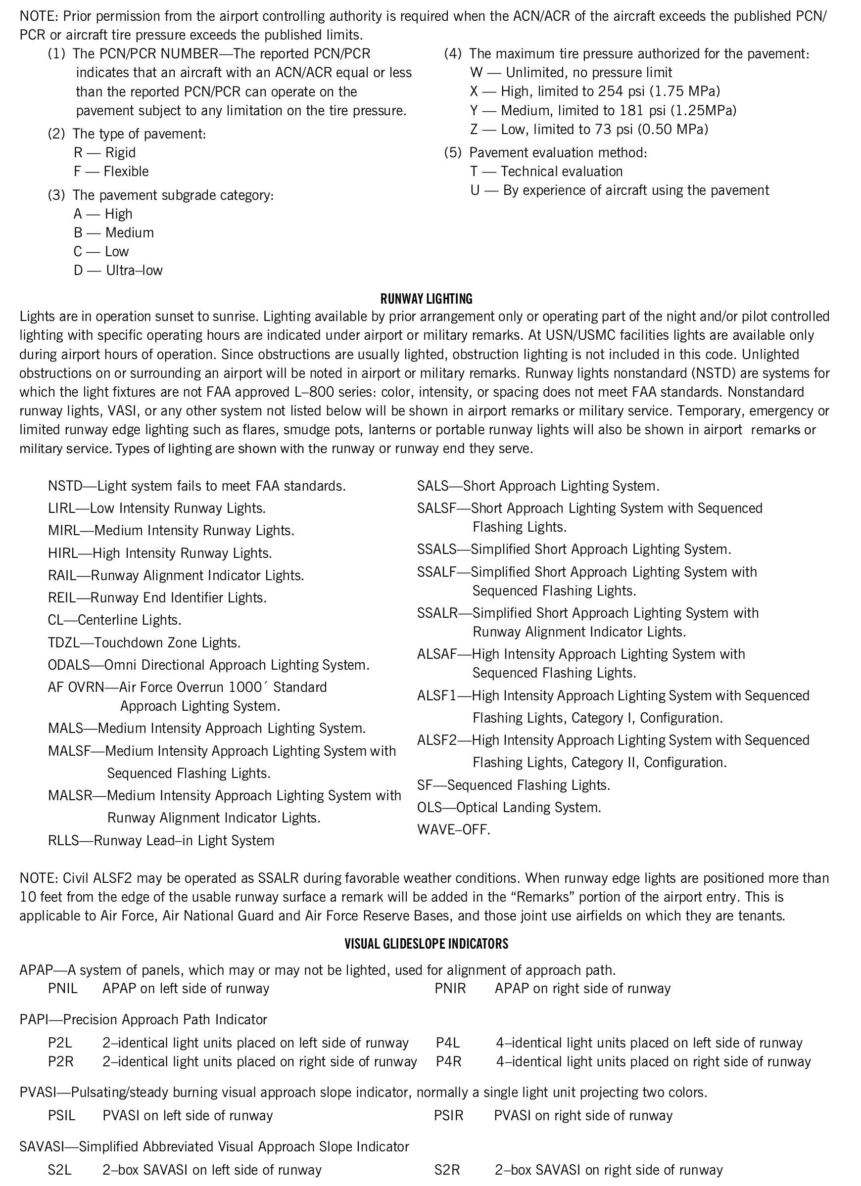
NOTE: Prior permission from the airport controlling authority is required when the ACN/ACR of the aircraft exceeds the published PCN/ PCR or aircraft tire pressure exceeds the published limits.
- (1) The PCN/PCR NUMBER—The reported PCN/PCR indicates that an aircraft with an ACN/ACR equal or less than the reported PCN/PCR can operate on the pavement subject to any limitation on the tire pressure.
- (2) The type of pavement: R — Rigid F — Flexible
- (3) The pavement subgrade category: A — High B — Medium C — Low D — Ultra–low
- (4) The maximum tire pressure authorized for the pavement: W — Unlimited, no pressure limit X — High, limited to 254 psi (1.75 MPa) Y — Medium, limited to 181 psi (1.25MPa) Z — Low, limited to 73 psi (0.50 MPa)
- (5) Pavement evaluation method: T — Technical evaluation U — By experience of aircraft using the pavement
RUNWAY LIGHTING
Lights are in operation sunset to sunrise. Lighting available by prior arrangement only or operating part of the night and/or pilot controlled lighting with specific operating hours are indicated under airport or military remarks. At USN/USMC facilities lights are available only during airport hours of operation. Since obstructions are usually lighted, obstruction lighting is not included in this code. Unlighted obstructions on or surrounding an airport will be noted in airport or military remarks. Runway lights nonstandard (NSTD) are systems for which the light fixtures are not FAA approved L–800 series: color, intensity, or spacing does not meet FAA standards. Nonstandard runway lights, VASI, or any other system not listed below will be shown in airport remarks or military service. Temporary, emergency or limited runway edge lighting such as flares, smudge pots, lanterns or portable runway lights will also be shown in airport remarks or military service. Types of lighting are shown with the runway or runway end they serve.
- NSTD—Light system fails to meet FAA standards.
- LIRL—Low Intensity Runway Lights.
- MIRL—Medium Intensity Runway Lights.
- HIRL—High Intensity Runway Lights.
- RAIL—Runway Alignment Indicator Lights.
- REIL—Runway End Identifier Lights.
- CL—Centerline Lights.
- TDZL—Touchdown Zone Lights.
- ODALS—Omni Directional Approach Lighting System.
- AF OVRN—Air Force Overrun 1000′ Standard Approach Lighting System.
- MALS—Medium Intensity Approach Lighting System.
- MALSF—Medium Intensity Approach Lighting System with Sequenced Flashing Lights.
- MALSR—Medium Intensity Approach Lighting System with Runway Alignment Indicator Lights.
- RLLS—Runway Lead–in Light System
- SALS—Short Approach Lighting System.
- SALSF—Short Approach Lighting System with Sequenced Flashing Lights.
- SSALS—Simplified Short Approach Lighting System.
- SSALF—Simplified Short Approach Lighting System with Sequenced Flashing Lights.
- SSALR—Simplified Short Approach Lighting System with Runway Alignment Indicator Lights.
- ALSAF—High Intensity Approach Lighting System with Sequenced Flashing Lights.
- ALSF1—High Intensity Approach Lighting System with Sequenced Flashing Lights, Category I, Configuration.
- ALSF2—High Intensity Approach Lighting System with Sequenced Flashing Lights, Category II, Configuration.
- SF—Sequenced Flashing Lights.
- OLS—Optical Landing System.
- WAVE–OFF.
NOTE: Civil ALSF2 may be operated as SSALR during favorable weather conditions. When runway edge lights are positioned more than 10 feet from the edge of the usable runway surface a remark will be added in the ‘Remarks’ portion of the airport entry. This is applicable to Air Force, Air National Guard and Air Force Reserve Bases, and those joint use airfields on which they are tenants.
VISUAL GLIDESLOPE INDICATORS
APAP—A system of panels, which may or may not be lighted, used for alignment of approach path.
| Code | Meaning |
|---|---|
| PNIL | APAP on left side of runway |
| Code | Meaning |
|---|---|
| PNIR | APAP on right side of runway |
PAPI—Precision Approach Path Indicator
| Code | Meaning |
|---|---|
| P2L | 2–identical light units placed on left side of runway |
| P2R | 2–identical light units placed on right side of runway |
| Code | Meaning |
|---|---|
| P4L | 4–identical light units placed on left side of runway |
| P4R | 4–identical light units placed on right side of runway |
PVASI—Pulsating/steady burning visual approach slope indicator, normally a single light unit projecting two colors.
| Code | Meaning |
|---|---|
| PSIL | PVASI on left side of runway |
| Code | Meaning |
|---|---|
| PSIR | PVASI on right side of runway |
SAVASI—Simplified Abbreviated Visual Approach Slope Indicator
| Code | Meaning |
|---|---|
| S2L | 2–box SAVASI on left side of runway |
| Code | Meaning |
|---|---|
| S2R | 2–box SAVASI on right side of runway |
SAVASI—Simplified Abbreviated Visual Approach Slope Indicator
| Code | Meaning |
|---|---|
| S2L | 2–box SAVASI on left side of runway |
| Code | Meaning |
|---|---|
| S2R | 2–box SAVASI on right side of runway |
TRCV—Tri–color visual approach slope indicator, normally a single light unit projecting three colors.
| Code | Meaning |
|---|---|
| TRIL | TRCV on left side of runway |
| Code | Meaning |
|---|---|
| TRIR | TRCV on right side of runway |
VASI—Visual Approach Slope Indicator
| Code | Meaning |
|---|---|
| V2L | 2–box VASI on left side of runway |
| V2R | 2–box VASI on right side of runway |
| V4L | 4–box VASI on left side of runway |
| V4R | 4–box VASI on right side of runway |
| Code | Meaning |
|---|---|
| V6L | 6–box VASI on left side of runway |
| V6R | 6–box VASI on right side of runway |
| V12 | 12–box VASI on both sides of runway |
| V16 | 16–box VASI on both sides of runway |
NOTE: Approach slope angle and threshold crossing height will be shown when available; i.e., –GA 3.5° TCH 37′.
| Code | Meaning |
|---|---|
| 7 times within 5 seconds | Highest intensity available |
| 5 times within 5 seconds | Medium or lower intensity (Lower REIL or REIL–Off) |
| 3 times within 5 seconds | Lowest intensity available (Lower REIL or REIL–Off) |
Available systems will be indicated in the Service section, e.g., LGT ACTIVATE HIRL Rwy 07–25, MALSR Rwy 07, and VASI Rwy 07— 122.8.
Where the airport is not served by an instrument approach procedure and/or has an independent type system of different specification installed by the airport sponsor, descriptions of the type lights, method of control, and operating frequency will be explained in clear text. See AIM, ‘Aeronautical Lighting and Other Airport Visual Aids,’ for a detailed description of pilot control of airport lighting.
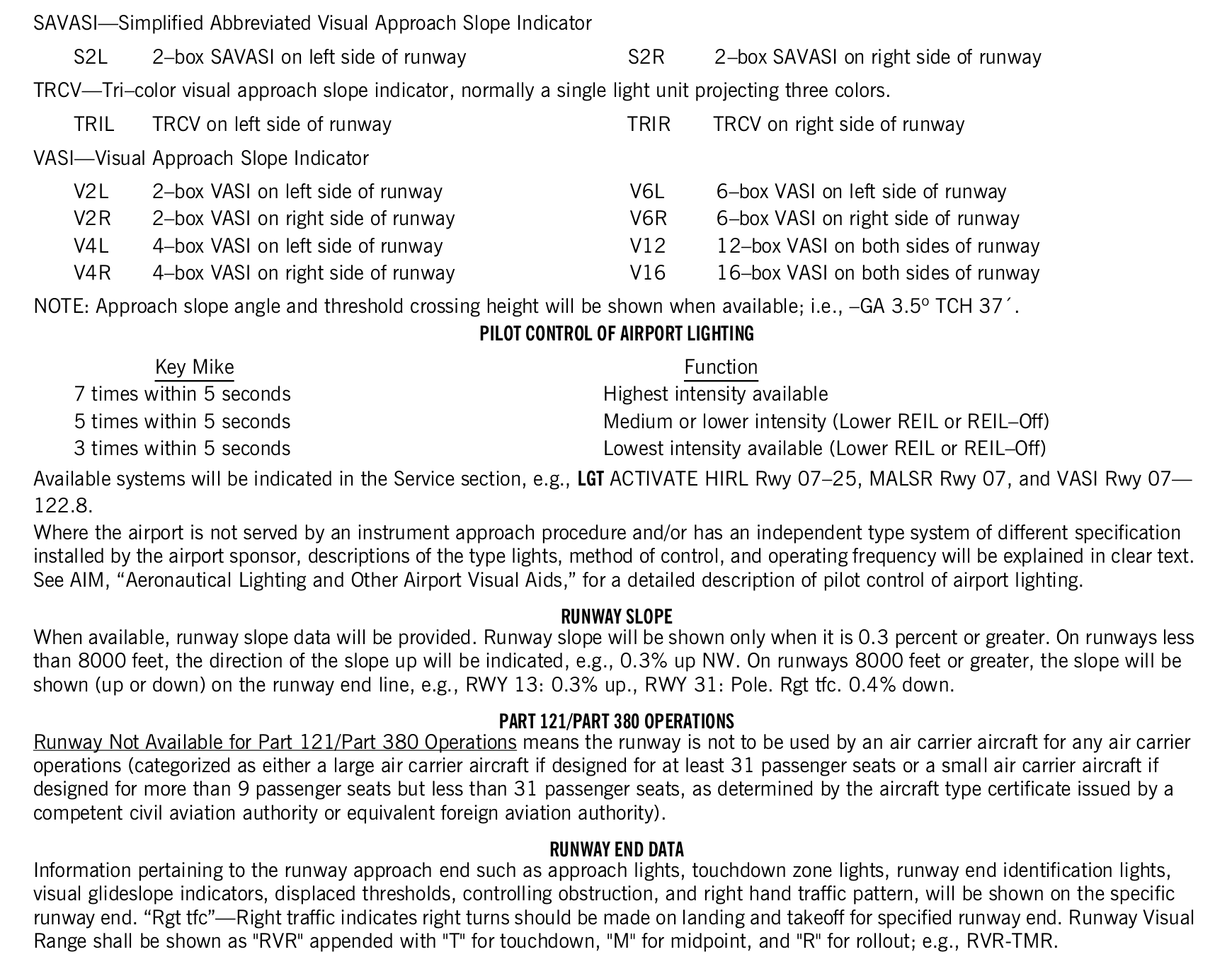
RUNWAY SLOPE
When available, runway slope data will be provided. Runway slope will be shown only when it is 0.3 percent or greater. On runways less than 8000 feet, the direction of the slope up will be indicated, e.g., 0.3% up NW. On runways 8000 feet or greater, the slope will be shown (up or down) on the runway end line, e.g., RWY 13: 0.3% up., RWY 31: Pole. Rgt tfc. 0.4% down.
PART 121/PART 380 OPERATIONS
Runway Not Available for Part 121/Part 380 Operations means the runway is not to be used by an air carrier aircraft for any air carrier operations (categorized as either a large air carrier aircraft if designed for at least 31 passenger seats or a small air carrier aircraft if designed for more than 9 passenger seats but less than 31 passenger seats, as determined by the aircraft type certificate issued by a competent civil aviation authority or equivalent foreign aviation authority).
RUNWAY END DATA
Information pertaining to the runway approach end such as approach lights, touchdown zone lights, runway end identification lights, visual glideslope indicators, displaced thresholds, controlling obstruction, and right hand traffic pattern, will be shown on the specific runway end. ‘Rgt tfc’—Right traffic indicates right turns should be made on landing and takeoff for specified runway end. Runway Visual Range shall be shown as "RVR" appended with "T" for touchdown, "M" for midpoint, and "R" for rollout; e.g., RVR-TMR.
View the FAA printed original (including tables)
20. Land and hold-short operations
FAA Pacific edition, printed page 17. Transcribed from the source legend; the printed original is available below.
LAND AND HOLD–SHORT OPERATIONS (LAHSO)
LAHSO is an acronym for “Land and Hold–Short Operations” These operations include landing and holding short of an intersection runway, an intersecting taxiway, or other predetermined points on the runway other than a runway or taxiway. Measured distance represents the available landing distance on the landing runway, in feet.
Specific questions regarding these distances should be referred to the air traffic manager of the facility concerned. The Aeronautical Information Manual contains specific details on hold–short operations and markings.
View the FAA printed original (including tables)

21. Runway declared distance information
FAA Pacific edition, printed page 17. Transcribed from the source legend; the printed original is available below.
TORA—Take–off Run Available. The length of runway declared available and suitable for the ground run of an aeroplane take–off. TODA—Take–off Distance Available. The length of the take–off run available plus the length of the clearway, if provided. ASDA—Accelerate–Stop Distance Available. The length of the take–off run available plus the length of the stopway, if provided. LDA—Landing Distance Available. The length of runway which is declared available and suitable for the ground run of an aeroplane landing.
View the FAA printed original (including tables)

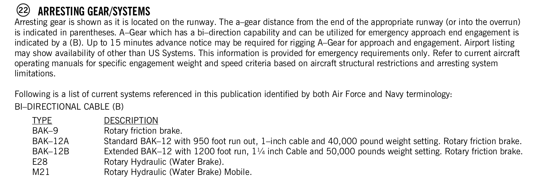
22. Arresting gear/systems
FAA Pacific edition, printed page 17–18. Transcribed from the source legend; the printed original is available below.
Arresting gear is shown as it is located on the runway. The a–gear distance from the end of the appropriate runway (or into the overrun) is indicated in parentheses. A–Gear which has a bi–direction capability and can be utilized for emergency approach end engagement is indicated by a (B). Up to 15 minutes advance notice may be required for rigging A–Gear for approach and engagement. Airport listing may show availability of other than US Systems. This information is provided for emergency requirements only. Refer to current aircraft operating manuals for specific engagement weight and speed criteria based on aircraft structural restrictions and arresting system limitations.
Following is a list of current systems referenced in this publication identified by both Air Force and Navy terminology: BI–DIRECTIONAL CABLE (B)
| Code | Meaning |
|---|---|
| BAK–9 | Rotary friction brake. |
| BAK–12A | Standard BAK–12 with 950 foot run out, 1–inch cable and 40,000 pound weight setting. Rotary friction brake. |
| BAK–12B | Extended BAK–12 with 1200 foot run, 1¼ inch Cable and 50,000 pounds weight setting. Rotary friction brake. |
| E28 | Rotary Hydraulic (Water Brake). |
| M21 | Rotary Hydraulic (Water Brake) Mobile. |
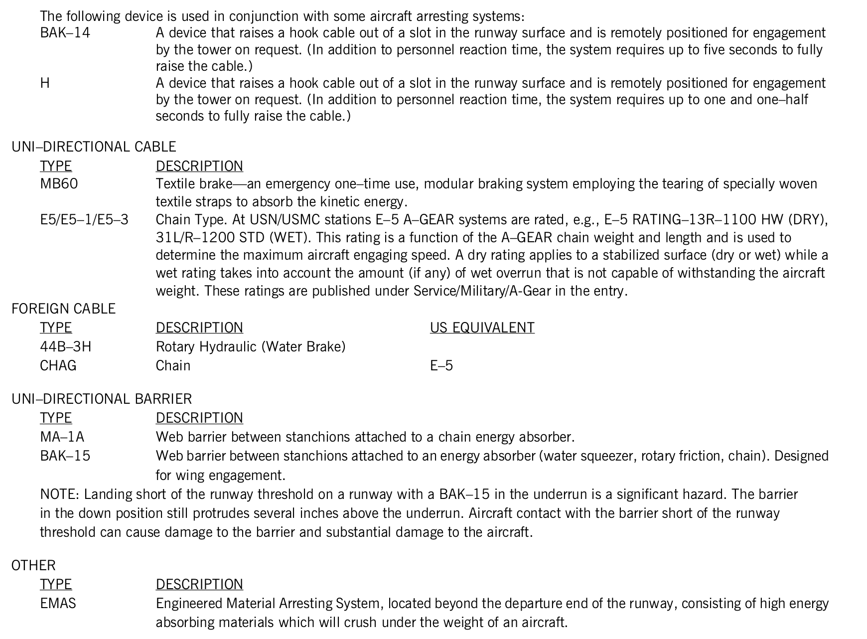
The following device is used in conjunction with some aircraft arresting systems:
| Code | Meaning |
|---|---|
| BAK–14 | A device that raises a hook cable out of a slot in the runway surface and is remotely positioned for engagement by the tower on request. (In addition to personnel reaction time, the system requires up to five seconds to fully raise the cable.) |
| H | A device that raises a hook cable out of a slot in the runway surface and is remotely positioned for engagement by the tower on request. (In addition to personnel reaction time, the system requires up to one and one–half seconds to fully raise the cable.) |
UNI–DIRECTIONAL CABLE
| Code | Meaning |
|---|---|
| MB60 | Textile brake—an emergency one–time use, modular braking system employing the tearing of specially woven textile straps to absorb the kinetic energy. |
| E5/E5–1/E5–3 | Chain Type. At USN/USMC stations E–5 A–GEAR systems are rated, e.g., E–5 RATING–13R–1100 HW (DRY), 31L/R–1200 STD (WET). This rating is a function of the A–GEAR chain weight and length and is used to determine the maximum aircraft engaging speed. A dry rating applies to a stabilized surface (dry or wet) while a wet rating takes into account the amount (if any) of wet overrun that is not capable of withstanding the aircraft weight. These ratings are published under Service/Military/A-Gear in the entry. |
FOREIGN CABLE
| Type | Description | US equivalent |
|---|---|---|
| 44B–3H | Rotary Hydraulic (Water Brake) | |
| CHAG | Chain | E–5 |
UNI–DIRECTIONAL BARRIER
| Code | Meaning |
|---|---|
| MA–1A | Web barrier between stanchions attached to a chain energy absorber. |
| BAK–15 | Web barrier between stanchions attached to an energy absorber (water squeezer, rotary friction, chain). Designed for wing engagement. |
NOTE: Landing short of the runway threshold on a runway with a BAK–15 in the underrun is a significant hazard. The barrier in the down position still protrudes several inches above the underrun. Aircraft contact with the barrier short of the runway threshold can cause damage to the barrier and substantial damage to the aircraft.
OTHER
| Code | Meaning |
|---|---|
| EMAS | Engineered Material Arresting System, located beyond the departure end of the runway, consisting of high energy absorbing materials which will crush under the weight of an aircraft. |
View the FAA printed original (including tables)
23. Service
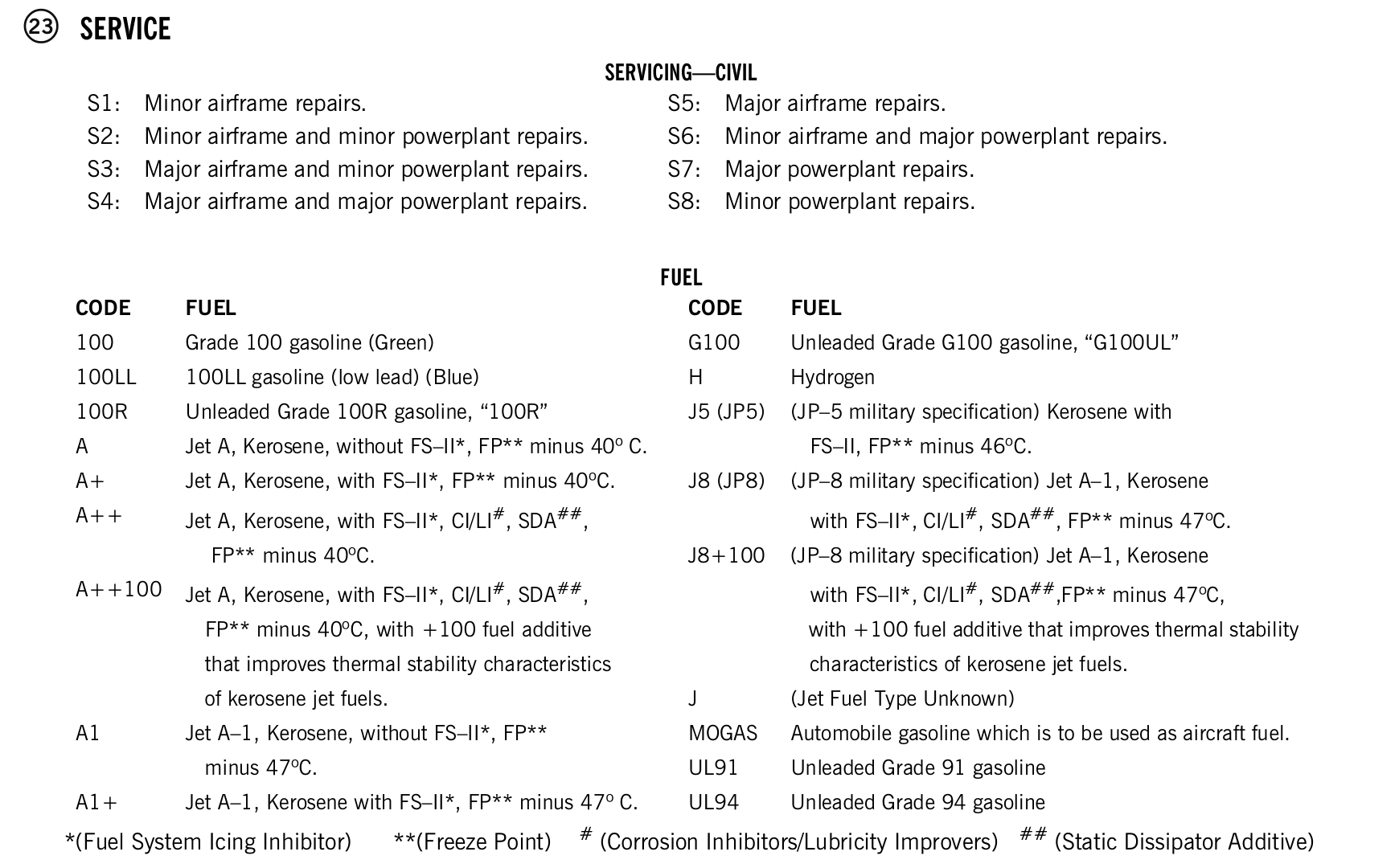
FAA Pacific edition, printed page 18–21. Transcribed from the source legend; the printed original is available below.
| Code | Meaning |
|---|---|
| S1: | Minor airframe repairs. |
| S2: | Minor airframe and minor powerplant repairs. |
| S3: | Major airframe and minor powerplant repairs. |
| S4: | Major airframe and major powerplant repairs. |
| Code | Meaning |
|---|---|
| S5: | Major airframe repairs. |
| S6: | Minor airframe and major powerplant repairs. |
| S7: | Major powerplant repairs. |
| S8: | Minor powerplant repairs. |
FUEL
| Code | Meaning |
|---|---|
| 100 | Grade 100 gasoline (Green) |
| 100LL | 100LL gasoline (low lead) (Blue) |
| 100R | Unleaded Grade 100R gasoline, ‘100R’ |
| A | Jet A, Kerosene, without FS–II*, FP** minus 40° C. |
| A+ | Jet A, Kerosene, with FS–II*, FP** minus 40°C. |
| A++ | Jet A, Kerosene, with FS–II*, CI/LI#, SDA##, FP** minus 40°C. |
| A++100 | Jet A, Kerosene, with FS–II*, CI/LI#, SDA##, FP** minus 40°C, with +100 fuel additive that improves thermal stability characteristics of kerosene jet fuels. |
| A1 | Jet A–1, Kerosene, without FS–II*, FP** minus 47°C. |
| A1+ | Jet A–1, Kerosene with FS–II*, FP** minus 47° C. |
| Code | Meaning |
|---|---|
| G100 | Unleaded Grade G100 gasoline, ‘G100UL’ |
| H | Hydrogen |
| J5 (JP5) | (JP–5 military specification) Kerosene with FS–II, FP** minus 46°C. |
| J8 (JP8) | (JP–8 military specification) Jet A–1, Kerosene with FS–II*, CI/LI#, SDA##, FP** minus 47°C. |
| J8+100 | (JP–8 military specification) Jet A–1, Kerosene with FS–II*, CI/LI#, SDA##,FP** minus 47°C, with +100 fuel additive that improves thermal stability characteristics of kerosene jet fuels. |
| J | (Jet Fuel Type Unknown) |
| MOGAS | Automobile gasoline which is to be used as aircraft fuel. |
| UL91 | Unleaded Grade 91 gasoline |
| UL94 | Unleaded Grade 94 gasoline |
*(Fuel System Icing Inhibitor) **(Freeze Point) # (Corrosion Inhibitors/Lubricity Improvers) ## (Static Dissipator Additive)
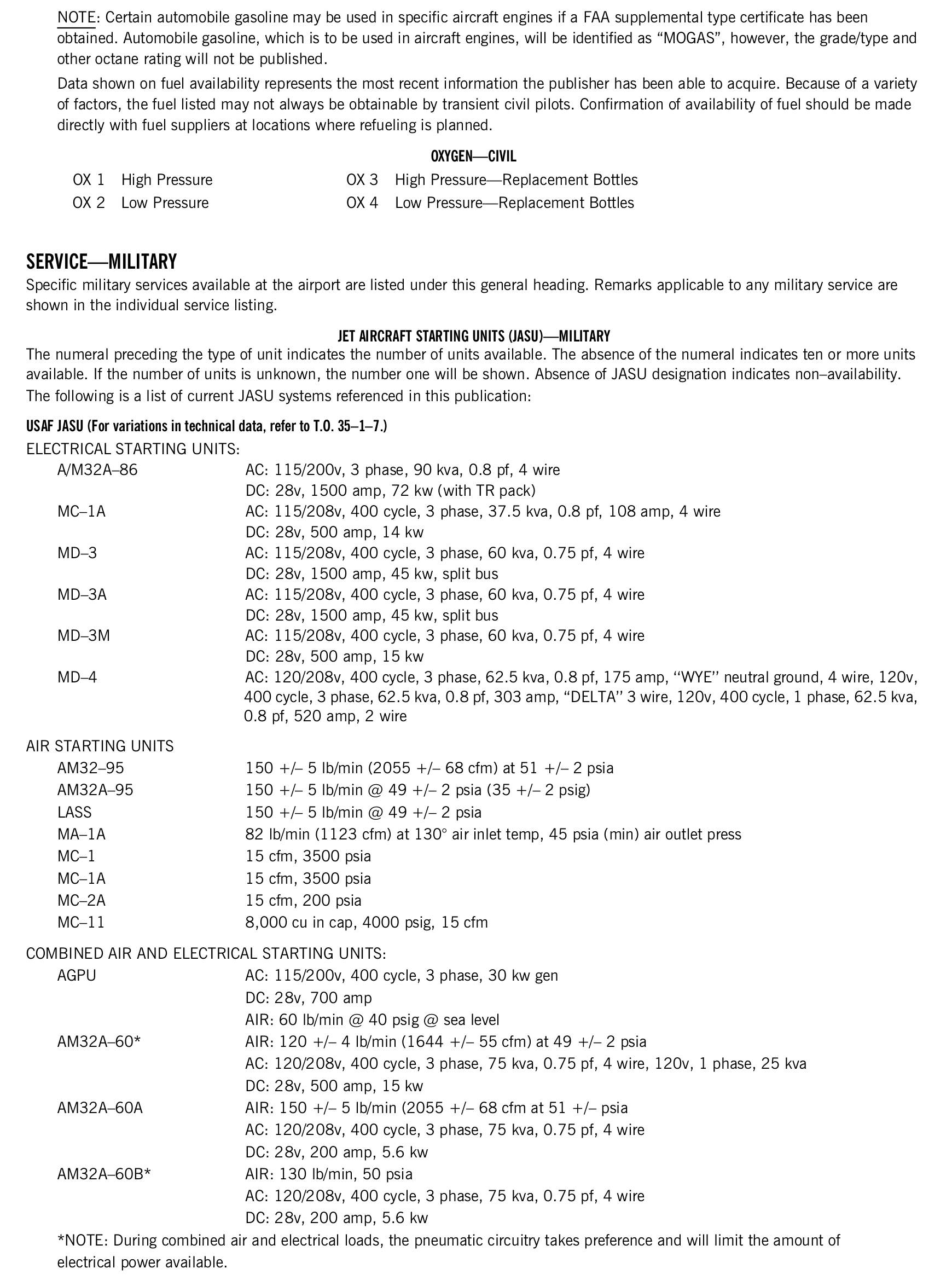
NOTE: Certain automobile gasoline may be used in specific aircraft engines if a FAA supplemental type certificate has been obtained. Automobile gasoline, which is to be used in aircraft engines, will be identified as ‘MOGAS’, however, the grade/type and other octane rating will not be published.
Data shown on fuel availability represents the most recent information the publisher has been able to acquire. Because of a variety of factors, the fuel listed may not always be obtainable by transient civil pilots. Confirmation of availability of fuel should be made directly with fuel suppliers at locations where refueling is planned.
| Code | Meaning |
|---|---|
| OX 1 | High Pressure |
| OX 2 | Low Pressure |
| Code | Meaning |
|---|---|
| OX 3 | High Pressure—Replacement Bottles |
| OX 4 | Low Pressure—Replacement Bottles |
SERVICE—MILITARY
Specific military services available at the airport are listed under this general heading. Remarks applicable to any military service are shown in the individual service listing.
JET AIRCRAFT STARTING UNITS (JASU)—MILITARY
The numeral preceding the type of unit indicates the number of units available. The absence of the numeral indicates ten or more units available. If the number of units is unknown, the number one will be shown. Absence of JASU designation indicates non–availability. The following is a list of current JASU systems referenced in this publication:
USAF JASU (For variations in technical data, refer to T.O. 35–1–7.)
ELECTRICAL STARTING UNITS:
| Code | Meaning |
|---|---|
| A/M32A–86 | AC: 115/200v, 3 phase, 90 kva, 0.8 pf, 4 wire DC: 28v, 1500 amp, 72 kw (with TR pack) |
| MC–1A | AC: 115/208v, 400 cycle, 3 phase, 37.5 kva, 0.8 pf, 108 amp, 4 wire DC: 28v, 500 amp, 14 kw |
| MD–3 | AC: 115/208v, 400 cycle, 3 phase, 60 kva, 0.75 pf, 4 wire DC: 28v, 1500 amp, 45 kw, split bus |
| MD–3A | AC: 115/208v, 400 cycle, 3 phase, 60 kva, 0.75 pf, 4 wire DC: 28v, 1500 amp, 45 kw, split bus |
| MD–3M | AC: 115/208v, 400 cycle, 3 phase, 60 kva, 0.75 pf, 4 wire DC: 28v, 500 amp, 15 kw |
| MD–4 | AC: 120/208v, 400 cycle, 3 phase, 62.5 kva, 0.8 pf, 175 amp, “WYE” neutral ground, 4 wire, 120v, 400 cycle, 3 phase, 62.5 kva, 0.8 pf, 303 amp, “DELTA” 3 wire, 120v, 400 cycle, 1 phase, 62.5 kva, 0.8 pf, 520 amp, 2 wire |
AIR STARTING UNITS
| Code | Meaning |
|---|---|
| AM32–95 | 150 +/– 5 lb/min (2055 +/– 68 cfm) at 51 +/– 2 psia |
| AM32A–95 | 150 +/– 5 lb/min @ 49 +/– 2 psia (35 +/– 2 psig) |
| LASS | 150 +/– 5 lb/min @ 49 +/– 2 psia |
| MA–1A | 82 lb/min (1123 cfm) at 130° air inlet temp, 45 psia (min) air outlet press |
| MC–1 | 15 cfm, 3500 psia |
| MC–1A | 15 cfm, 3500 psia |
| MC–2A | 15 cfm, 200 psia |
| MC–11 | 8,000 cu in cap, 4000 psig, 15 cfm |
COMBINED AIR AND ELECTRICAL STARTING UNITS:
| Code | Meaning |
|---|---|
| AGPU | AC: 115/200v, 400 cycle, 3 phase, 30 kw gen DC: 28v, 700 amp AIR: 60 lb/min @ 40 psig @ sea level |
| AM32A–60* | AIR: 120 +/– 4 lb/min (1644 +/– 55 cfm) at 49 +/– 2 psia AC: 120/208v, 400 cycle, 3 phase, 75 kva, 0.75 pf, 4 wire, 120v, 1 phase, 25 kva DC: 28v, 500 amp, 15 kw |
| AM32A–60A | AIR: 150 +/– 5 lb/min (2055 +/– 68 cfm at 51 +/– psia AC: 120/208v, 400 cycle, 3 phase, 75 kva, 0.75 pf, 4 wire DC: 28v, 200 amp, 5.6 kw |
| AM32A–60B* | AIR: 130 lb/min, 50 psia AC: 120/208v, 400 cycle, 3 phase, 75 kva, 0.75 pf, 4 wire DC: 28v, 200 amp, 5.6 kw |
*NOTE: During combined air and electrical loads, the pneumatic circuitry takes preference and will limit the amount of electrical power available.
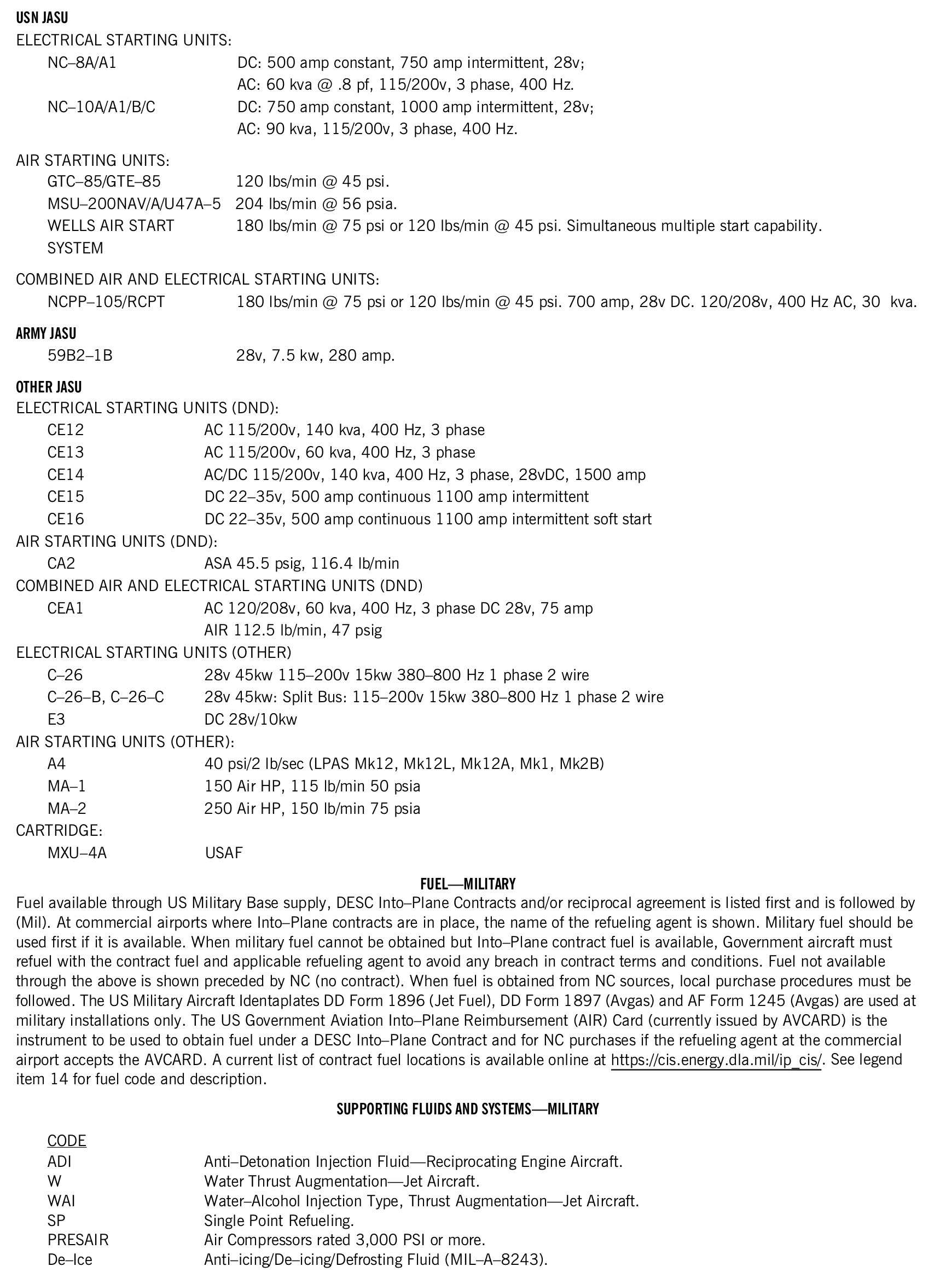
USN JASU
ELECTRICAL STARTING UNITS:
| Code | Meaning |
|---|---|
| NC–8A/A1 | DC: 500 amp constant, 750 amp intermittent, 28v; AC: 60 kva @ .8 pf, 115/200v, 3 phase, 400 Hz. |
| NC–10A/A1/B/C | DC: 750 amp constant, 1000 amp intermittent, 28v; AC: 90 kva, 115/200v, 3 phase, 400 Hz. |
AIR STARTING UNITS:
| Code | Meaning |
|---|---|
| GTC–85/GTE–85 | 120 lbs/min @ 45 psi. |
| MSU–200NAV/A/U47A–5 | 204 lbs/min @ 56 psia. |
| WELLS AIR START SYSTEM | 180 lbs/min @ 75 psi or 120 lbs/min @ 45 psi. Simultaneous multiple start capability. |
COMBINED AIR AND ELECTRICAL STARTING UNITS:
| Code | Meaning |
|---|---|
| NCPP–105/RCPT | 180 lbs/min @ 75 psi or 120 lbs/min @ 45 psi. 700 amp, 28v DC. 120/208v, 400 Hz AC, 30 kva. |
| Code | Meaning |
|---|---|
| 59B2–1B | 28v, 7.5 kw, 280 amp. |
OTHER JASU
ELECTRICAL STARTING UNITS (DND):
| Code | Meaning |
|---|---|
| CE12 | AC 115/200v, 140 kva, 400 Hz, 3 phase |
| CE13 | AC 115/200v, 60 kva, 400 Hz, 3 phase |
| CE14 | AC/DC 115/200v, 140 kva, 400 Hz, 3 phase, 28vDC, 1500 amp |
| CE15 | DC 22–35v, 500 amp continuous 1100 amp intermittent |
| CE16 | DC 22–35v, 500 amp continuous 1100 amp intermittent soft start |
AIR STARTING UNITS (DND):
| Code | Meaning |
|---|---|
| CA2 | ASA 45.5 psig, 116.4 lb/min |
COMBINED AIR AND ELECTRICAL STARTING UNITS (DND)
| Code | Meaning |
|---|---|
| CEA1 | AC 120/208v, 60 kva, 400 Hz, 3 phase DC 28v, 75 amp AIR 112.5 lb/min, 47 psig |
ELECTRICAL STARTING UNITS (OTHER)
| Code | Meaning |
|---|---|
| C–26 | 28v 45kw 115–200v 15kw 380–800 Hz 1 phase 2 wire |
| C–26–B, C–26–C | 28v 45kw: Split Bus: 115–200v 15kw 380–800 Hz 1 phase 2 wire |
| E3 | DC 28v/10kw |
AIR STARTING UNITS (OTHER):
| Code | Meaning |
|---|---|
| A4 | 40 psi/2 lb/sec (LPAS Mk12, Mk12L, Mk12A, Mk1, Mk2B) |
| MA–1 | 150 Air HP, 115 lb/min 50 psia |
| MA–2 | 250 Air HP, 150 lb/min 75 psia |
CARTRIDGE:
| Code | Meaning |
|---|---|
| MXU–4A | USAF |
FUEL—MILITARY
Fuel available through US Military Base supply, DESC Into–Plane Contracts and/or reciprocal agreement is listed first and is followed by (Mil). At commercial airports where Into–Plane contracts are in place, the name of the refueling agent is shown. Military fuel should be used first if it is available. When military fuel cannot be obtained but Into–Plane contract fuel is available, Government aircraft must refuel with the contract fuel and applicable refueling agent to avoid any breach in contract terms and conditions. Fuel not available through the above is shown preceded by NC (no contract). When fuel is obtained from NC sources, local purchase procedures must be followed. The US Military Aircraft Identaplates DD Form 1896 (Jet Fuel), DD Form 1897 (Avgas) and AF Form 1245 (Avgas) are used at military installations only. The US Government Aviation Into–Plane Reimbursement (AIR) Card (currently issued by AVCARD) is the instrument to be used to obtain fuel under a DESC Into–Plane Contract and for NC purchases if the refueling agent at the commercial airport accepts the AVCARD. A current list of contract fuel locations is available online at https://cis.energy.dla.mil/ip_cis/. See legend item 14 for fuel code and description.
| Code | Meaning |
|---|---|
| ADI | Anti–Detonation Injection Fluid—Reciprocating Engine Aircraft. |
| W | Water Thrust Augmentation—Jet Aircraft. |
| WAI | Water–Alcohol Injection Type, Thrust Augmentation—Jet Aircraft. |
| SP | Single Point Refueling. |
| PRESAIR | Air Compressors rated 3,000 PSI or more. |
| De–Ice | Anti–icing/De–icing/Defrosting Fluid (MIL–A–8243). |
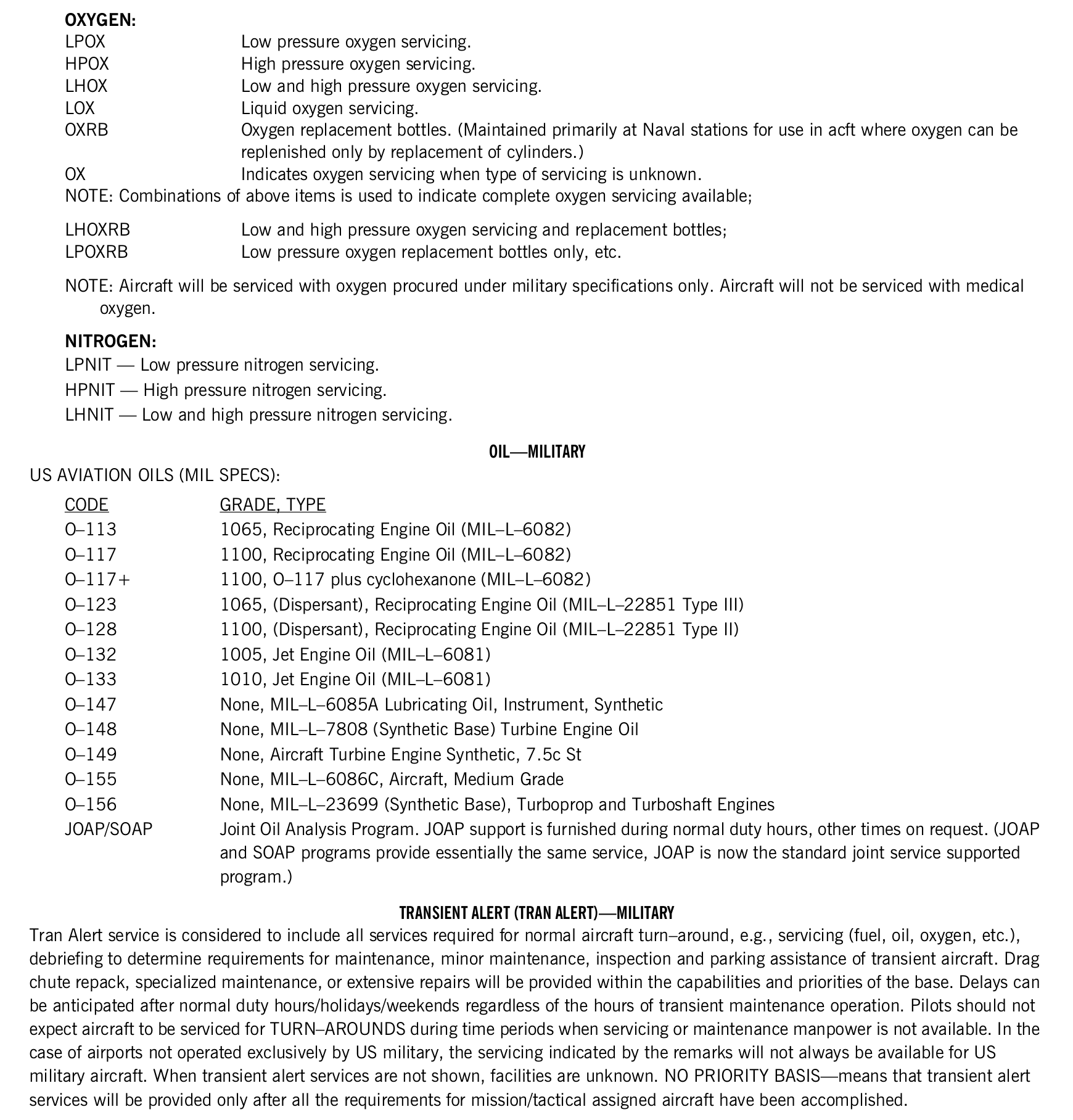
OXYGEN:
| Code | Meaning |
|---|---|
| LPOX | Low pressure oxygen servicing. |
| HPOX | High pressure oxygen servicing. |
| LHOX | Low and high pressure oxygen servicing. |
| LOX | Liquid oxygen servicing. |
| OXRB | Oxygen replacement bottles. (Maintained primarily at Naval stations for use in acft where oxygen can be replenished only by replacement of cylinders.) |
| OX | Indicates oxygen servicing when type of servicing is unknown. |
NOTE: Combinations of above items is used to indicate complete oxygen servicing available;
| Code | Meaning |
|---|---|
| LHOXRB | Low and high pressure oxygen servicing and replacement bottles; |
| LPOXRB | Low pressure oxygen replacement bottles only, etc. |
NOTE: Aircraft will be serviced with oxygen procured under military specifications only. Aircraft will not be serviced with medical oxygen.
NITROGEN:
LPNIT — Low pressure nitrogen servicing.
HPNIT — High pressure nitrogen servicing.
LHNIT — Low and high pressure nitrogen servicing.
OIL—MILITARY
US AVIATION OILS (MIL SPECS):
| Code | Meaning |
|---|---|
| O–113 | 1065, Reciprocating Engine Oil (MIL–L–6082) |
| O–117 | 1100, Reciprocating Engine Oil (MIL–L–6082) |
| O–117+ | 1100, O–117 plus cyclohexanone (MIL–L–6082) |
| O–123 | 1065, (Dispersant), Reciprocating Engine Oil (MIL–L–22851 Type III) |
| O–128 | 1100, (Dispersant), Reciprocating Engine Oil (MIL–L–22851 Type II) |
| O–132 | 1005, Jet Engine Oil (MIL–L–6081) |
| O–133 | 1010, Jet Engine Oil (MIL–L–6081) |
| O–147 | None, MIL–L–6085A Lubricating Oil, Instrument, Synthetic |
| O–148 | None, MIL–L–7808 (Synthetic Base) Turbine Engine Oil |
| O–149 | None, Aircraft Turbine Engine Synthetic, 7.5c St |
| O–155 | None, MIL–L–6086C, Aircraft, Medium Grade |
| O–156 | None, MIL–L–23699 (Synthetic Base), Turboprop and Turboshaft Engines |
| JOAP/SOAP | Joint Oil Analysis Program. JOAP support is furnished during normal duty hours, other times on request. (JOAP and SOAP programs provide essentially the same service, JOAP is now the standard joint service supported program.) |
TRANSIENT ALERT (TRAN ALERT)—MILITARY
Tran Alert service is considered to include all services required for normal aircraft turn–around, e.g., servicing (fuel, oil, oxygen, etc.), debriefing to determine requirements for maintenance, minor maintenance, inspection and parking assistance of transient aircraft. Drag chute repack, specialized maintenance, or extensive repairs will be provided within the capabilities and priorities of the base. Delays can be anticipated after normal duty hours/holidays/weekends regardless of the hours of transient maintenance operation. Pilots should not expect aircraft to be serviced for TURN–AROUNDS during time periods when servicing or maintenance manpower is not available. In the case of airports not operated exclusively by US military, the servicing indicated by the remarks will not always be available for US military aircraft. When transient alert services are not shown, facilities are unknown. NO PRIORITY BASIS—means that transient alert services will be provided only after all the requirements for mission/tactical assigned aircraft have been accomplished.
View the FAA printed original (including tables)
24. Noise
FAA Pacific edition, printed page 21. Transcribed from the source legend; the printed original is available below.
Remarks that indicate noise information and/or abatement measures that exist in the vicinity of the airport.
View the FAA printed original (including tables)

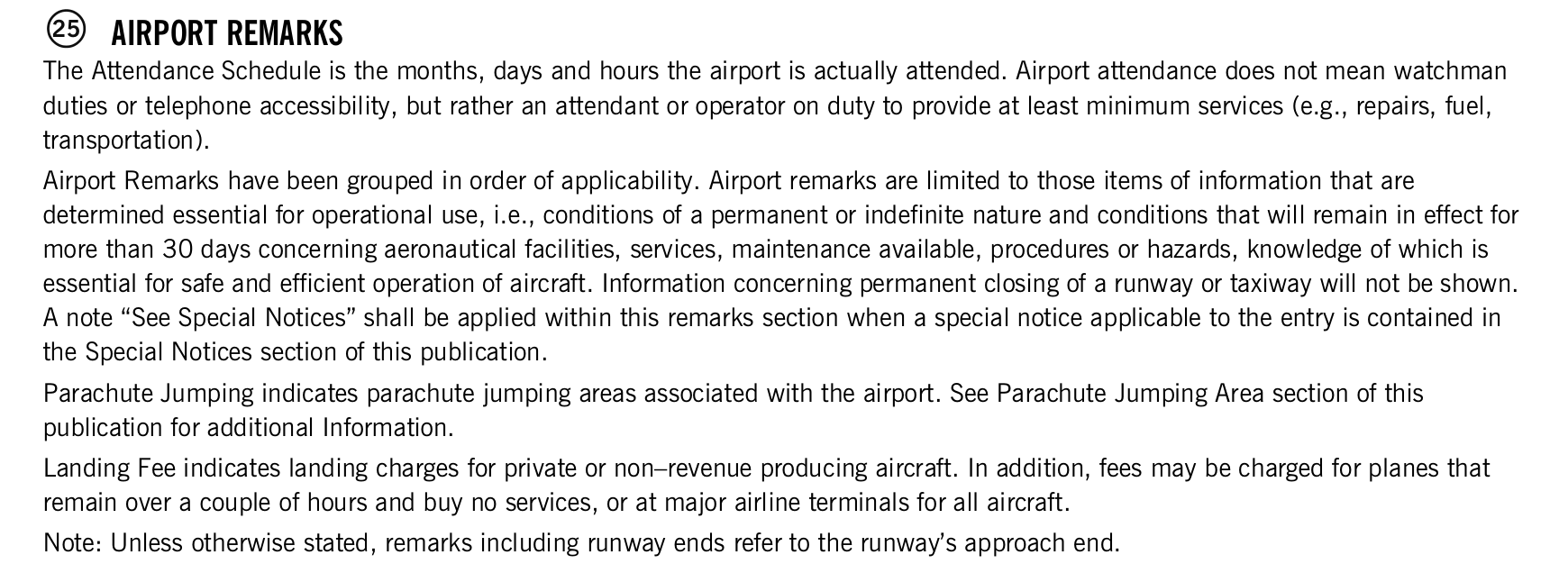
25. Airport remarks
FAA Pacific edition, printed page 21–22. Transcribed from the source legend; the printed original is available below.
The Attendance Schedule is the months, days and hours the airport is actually attended. Airport attendance does not mean watchman duties or telephone accessibility, but rather an attendant or operator on duty to provide at least minimum services (e.g., repairs, fuel, transportation).
Airport Remarks have been grouped in order of applicability. Airport remarks are limited to those items of information that are determined essential for operational use, i.e., conditions of a permanent or indefinite nature and conditions that will remain in effect for more than 30 days concerning aeronautical facilities, services, maintenance available, procedures or hazards, knowledge of which is essential for safe and efficient operation of aircraft. Information concerning permanent closing of a runway or taxiway will not be shown. A note ‘See Special Notices’ shall be applied within this remarks section when a special notice applicable to the entry is contained in the Special Notices section of this publication.
Parachute Jumping indicates parachute jumping areas associated with the airport. See Parachute Jumping Area section of this publication for additional Information.
Landing Fee indicates landing charges for private or non–revenue producing aircraft. In addition, fees may be charged for planes that remain over a couple of hours and buy no services, or at major airline terminals for all aircraft.
Note: Unless otherwise stated, remarks including runway ends refer to the runway’s approach end.
View the FAA printed original (including tables)
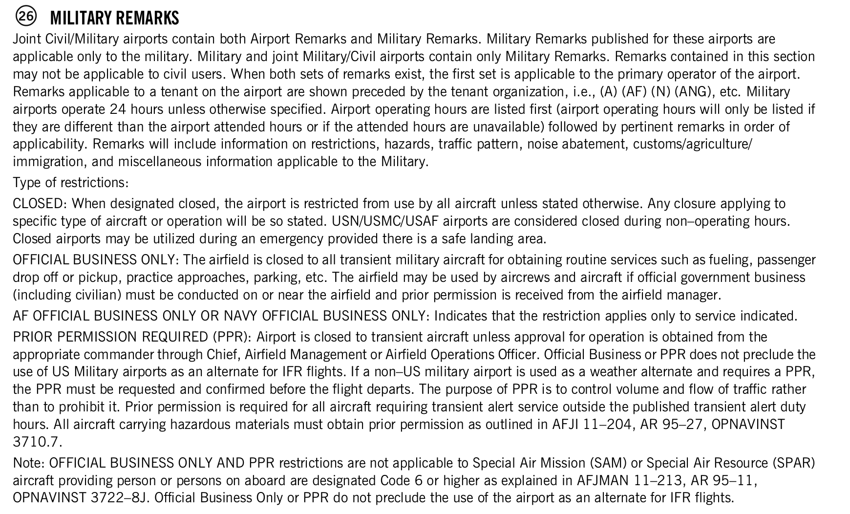
26. Military remarks
FAA Pacific edition, printed page 22. Transcribed from the source legend; the printed original is available below.
Joint Civil/Military airports contain both Airport Remarks and Military Remarks. Military Remarks published for these airports are applicable only to the military. Military and joint Military/Civil airports contain only Military Remarks. Remarks contained in this section may not be applicable to civil users. When both sets of remarks exist, the first set is applicable to the primary operator of the airport. Remarks applicable to a tenant on the airport are shown preceded by the tenant organization, i.e., (A) (AF) (N) (ANG), etc. Military airports operate 24 hours unless otherwise specified. Airport operating hours are listed first (airport operating hours will only be listed if they are different than the airport attended hours or if the attended hours are unavailable) followed by pertinent remarks in order of applicability. Remarks will include information on restrictions, hazards, traffic pattern, noise abatement, customs/agriculture/ immigration, and miscellaneous information applicable to the Military.
Type of restrictions:
CLOSED: When designated closed, the airport is restricted from use by all aircraft unless stated otherwise. Any closure applying to specific type of aircraft or operation will be so stated. USN/USMC/USAF airports are considered closed during non–operating hours. Closed airports may be utilized during an emergency provided there is a safe landing area.
OFFICIAL BUSINESS ONLY: The airfield is closed to all transient military aircraft for obtaining routine services such as fueling, passenger drop off or pickup, practice approaches, parking, etc. The airfield may be used by aircrews and aircraft if official government business (including civilian) must be conducted on or near the airfield and prior permission is received from the airfield manager. AF OFFICIAL BUSINESS ONLY OR NAVY OFFICIAL BUSINESS ONLY: Indicates that the restriction applies only to service indicated. PRIOR PERMISSION REQUIRED (PPR): Airport is closed to transient aircraft unless approval for operation is obtained from the appropriate commander through Chief, Airfield Management or Airfield Operations Officer. Official Business or PPR does not preclude the use of US Military airports as an alternate for IFR flights. If a non–US military airport is used as a weather alternate and requires a PPR, the PPR must be requested and confirmed before the flight departs. The purpose of PPR is to control volume and flow of traffic rather than to prohibit it. Prior permission is required for all aircraft requiring transient alert service outside the published transient alert duty hours. All aircraft carrying hazardous materials must obtain prior permission as outlined in AFJI 11–204, AR 95–27, OPNAVINST 3710.7.
Note: OFFICIAL BUSINESS ONLY AND PPR restrictions are not applicable to Special Air Mission (SAM) or Special Air Resource (SPAR) aircraft providing person or persons on aboard are designated Code 6 or higher as explained in AFJMAN 11–213, AR 95–11, OPNAVINST 3722–8J. Official Business Only or PPR do not preclude the use of the airport as an alternate for IFR flights.
View the FAA printed original (including tables)
27. Airport manager
FAA Pacific edition, printed page 22. Transcribed from the source legend; the printed original is available below.
The phone number of the airport manager.
View the FAA printed original (including tables)

28. Weather data sources
FAA Pacific edition, printed page 22–23. Transcribed from the source legend; the printed original is available below.
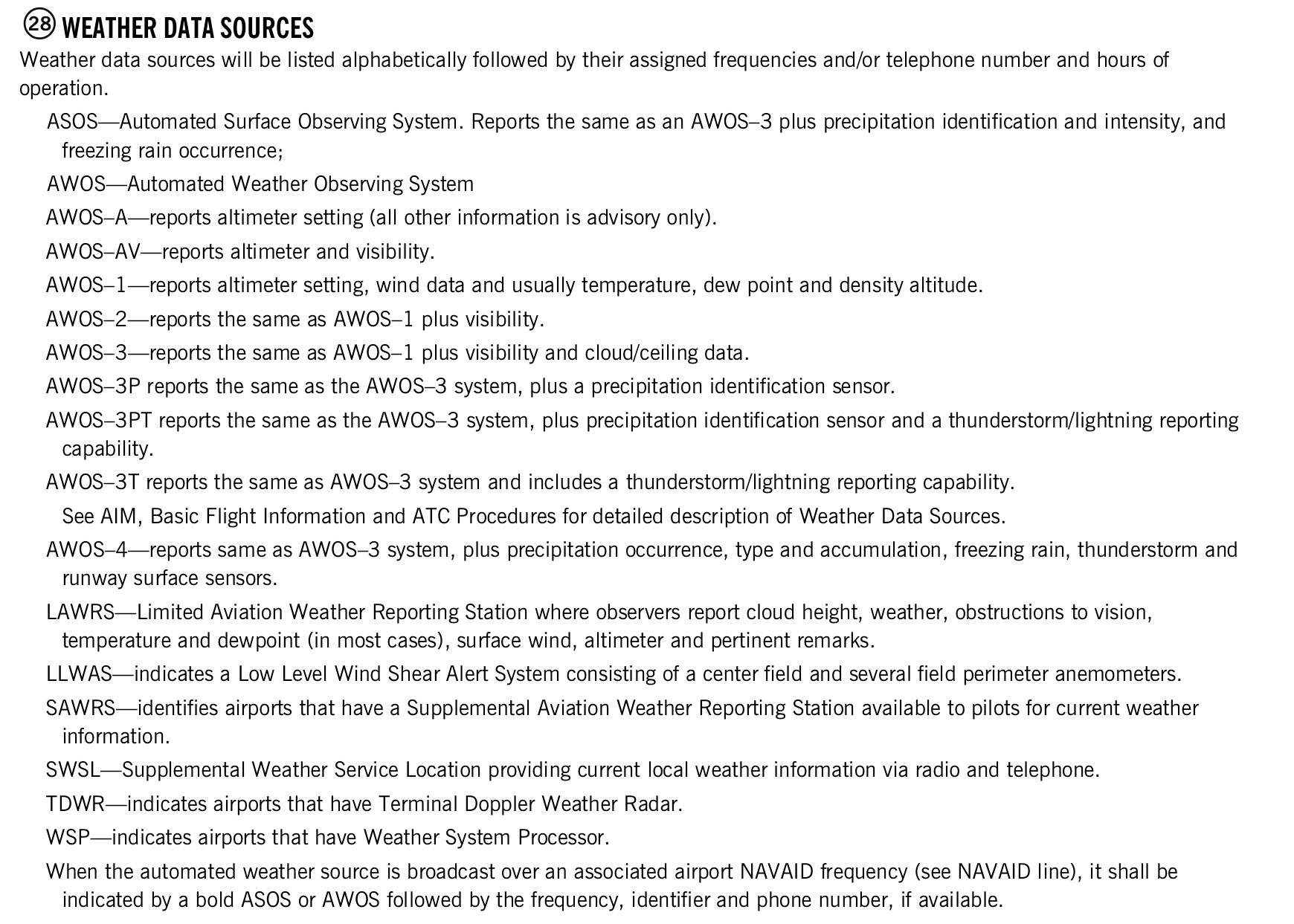
Weather data sources will be listed alphabetically followed by their assigned frequencies and/or telephone number and hours of operation.
ASOS—Automated Surface Observing System. Reports the same as an AWOS–3 plus precipitation identification and intensity, and freezing rain occurrence;
AWOS—Automated Weather Observing System
AWOS–A—reports altimeter setting (all other information is advisory only).
AWOS–AV—reports altimeter and visibility.
AWOS–1—reports altimeter setting, wind data and usually temperature, dew point and density altitude.
AWOS–2—reports the same as AWOS–1 plus visibility.
AWOS–3—reports the same as AWOS–1 plus visibility and cloud/ceiling data.
AWOS–3P reports the same as the AWOS–3 system, plus a precipitation identification sensor.
AWOS–3PT reports the same as the AWOS–3 system, plus precipitation identification sensor and a thunderstorm/lightning reporting capability.
AWOS–3T reports the same as AWOS–3 system and includes a thunderstorm/lightning reporting capability.
See AIM, Basic Flight Information and ATC Procedures for detailed description of Weather Data Sources.
AWOS–4—reports same as AWOS–3 system, plus precipitation occurrence, type and accumulation, freezing rain, thunderstorm and runway surface sensors.
LAWRS—Limited Aviation Weather Reporting Station where observers report cloud height, weather, obstructions to vision, temperature and dewpoint (in most cases), surface wind, altimeter and pertinent remarks.
LLWAS—indicates a Low Level Wind Shear Alert System consisting of a center field and several field perimeter anemometers.
SAWRS—identifies airports that have a Supplemental Aviation Weather Reporting Station available to pilots for current weather information.
SWSL—Supplemental Weather Service Location providing current local weather information via radio and telephone.
TDWR—indicates airports that have Terminal Doppler Weather Radar.
WSP—indicates airports that have Weather System Processor.
When the automated weather source is broadcast over an associated airport NAVAID frequency (see NAVAID line), it shall be indicated by a bold ASOS or AWOS followed by the frequency, identifier and phone number, if available.
View the FAA printed original (including tables)
29. Communications
FAA Pacific edition, printed page 23–24. Transcribed from the source legend; the printed original is available below.
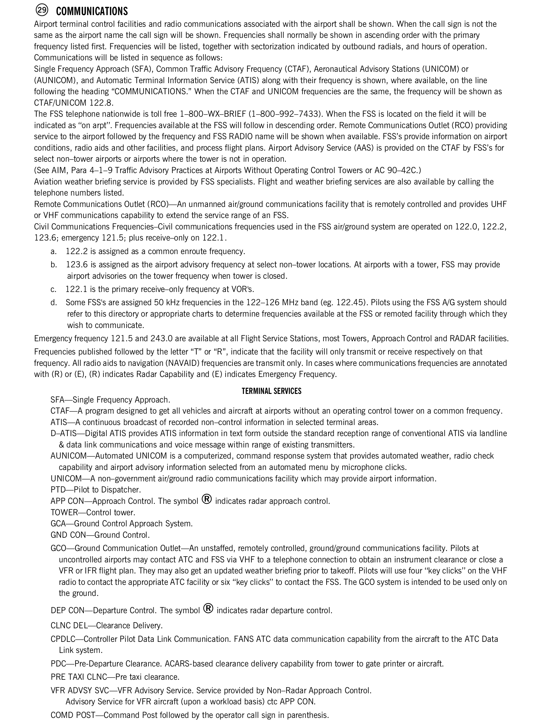
Airport terminal control facilities and radio communications associated with the airport shall be shown. When the call sign is not the same as the airport name the call sign will be shown. Frequencies shall normally be shown in ascending order with the primary frequency listed first. Frequencies will be listed, together with sectorization indicated by outbound radials, and hours of operation. Communications will be listed in sequence as follows:
Single Frequency Approach (SFA), Common Traffic Advisory Frequency (CTAF), Aeronautical Advisory Stations (UNICOM) or (AUNICOM), and Automatic Terminal Information Service (ATIS) along with their frequency is shown, where available, on the line following the heading ‘COMMUNICATIONS.’ When the CTAF and UNICOM frequencies are the same, the frequency will be shown as CTAF/UNICOM 122.8.
The FSS telephone nationwide is toll free 1–800–WX–BRIEF (1–800–992–7433). When the FSS is located on the field it will be indicated as “on arpt”. Frequencies available at the FSS will follow in descending order. Remote Communications Outlet (RCO) providing service to the airport followed by the frequency and FSS RADIO name will be shown when available. FSS’s provide information on airport conditions, radio aids and other facilities, and process flight plans. Airport Advisory Service (AAS) is provided on the CTAF by FSS’s for select non–tower airports or airports where the tower is not in operation.
(See AIM, Para 4–1–9 Traffic Advisory Practices at Airports Without Operating Control Towers or AC 90–42C.)
Aviation weather briefing service is provided by FSS specialists. Flight and weather briefing services are also available by calling the telephone numbers listed.
Remote Communications Outlet (RCO)—An unmanned air/ground communications facility that is remotely controlled and provides UHF or VHF communications capability to extend the service range of an FSS.
Civil Communications Frequencies–Civil communications frequencies used in the FSS air/ground system are operated on 122.0, 122.2, 123.6; emergency 121.5; plus receive–only on 122.1.
a. 122.2 is assigned as a common enroute frequency.
b. 123.6 is assigned as the airport advisory frequency at select non–tower locations. At airports with a tower, FSS may provide airport advisories on the tower frequency when tower is closed.
c. 122.1 is the primary receive–only frequency at VOR's.
d. Some FSS's are assigned 50 kHz frequencies in the 122–126 MHz band (eg. 122.45). Pilots using the FSS A/G system should refer to this directory or appropriate charts to determine frequencies available at the FSS or remoted facility through which they wish to communicate.
Emergency frequency 121.5 and 243.0 are available at all Flight Service Stations, most Towers, Approach Control and RADAR facilities.
Frequencies published followed by the letter ‘T’ or ‘R’, indicate that the facility will only transmit or receive respectively on that frequency. All radio aids to navigation (NAVAID) frequencies are transmit only. In cases where communications frequencies are annotated with (R) or (E), (R) indicates Radar Capability and (E) indicates Emergency Frequency.
TERMINAL SERVICES
SFA—Single Frequency Approach.
CTAF—A program designed to get all vehicles and aircraft at airports without an operating control tower on a common frequency. ATIS—A continuous broadcast of recorded non–control information in selected terminal areas.
D–ATIS—Digital ATIS provides ATIS information in text form outside the standard reception range of conventional ATIS via landline & data link communications and voice message within range of existing transmitters.
AUNICOM—Automated UNICOM is a computerized, command response system that provides automated weather, radio check capability and airport advisory information selected from an automated menu by microphone clicks.
UNICOM—A non–government air/ground radio communications facility which may provide airport information.
PTD—Pilot to Dispatcher.
APP CON—Approach Control. The symbol ® indicates radar approach control.
TOWER—Control tower.
GCA—Ground Control Approach System.
GND CON—Ground Control.
GCO—Ground Communication Outlet—An unstaffed, remotely controlled, ground/ground communications facility. Pilots at uncontrolled airports may contact ATC and FSS via VHF to a telephone connection to obtain an instrument clearance or close a VFR or IFR flight plan. They may also get an updated weather briefing prior to takeoff. Pilots will use four “key clicks” on the VHF radio to contact the appropriate ATC facility or six “key clicks” to contact the FSS. The GCO system is intended to be used only on the ground.
DEP CON—Departure Control. The symbol ® indicates radar departure control.
CLNC DEL—Clearance Delivery.
CPDLC—Controller Pilot Data Link Communication. FANS ATC data communication capability from the aircraft to the ATC Data Link system.
PDC—Pre-Departure Clearance. ACARS-based clearance delivery capability from tower to gate printer or aircraft.
PRE TAXI CLNC—Pre taxi clearance.
VFR ADVSY SVC—VFR Advisory Service. Service provided by Non–Radar Approach Control.
Advisory Service for VFR aircraft (upon a workload basis) ctc APP CON.
COMD POST—Command Post followed by the operator call sign in parenthesis.
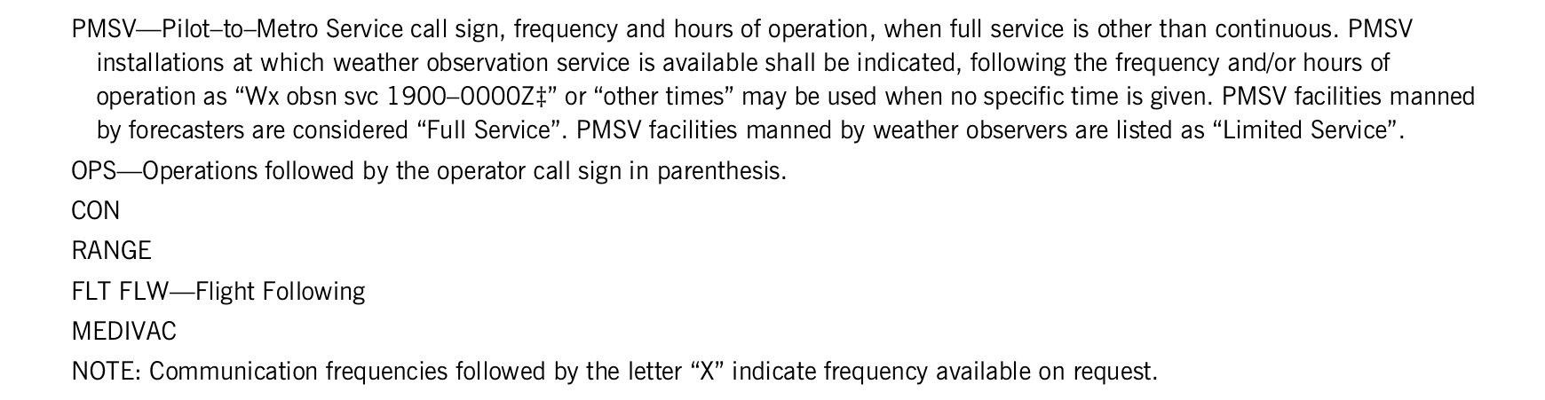
PMSV—Pilot–to–Metro Service call sign, frequency and hours of operation, when full service is other than continuous. PMSV installations at which weather observation service is available shall be indicated, following the frequency and/or hours of operation as ‘Wx obsn svc 1900–0000Z‡’ or ‘other times’ may be used when no specific time is given. PMSV facilities manned by forecasters are considered ‘Full Service’. PMSV facilities manned by weather observers are listed as ‘Limited Service’.
OPS—Operations followed by the operator call sign in parenthesis.
CON
RANGE
FLT FLW—Flight Following
MEDIVAC
NOTE: Communication frequencies followed by the letter ‘X’ indicate frequency available on request.
View the FAA printed original (including tables)
30. Airspace
FAA Pacific edition, printed page 24. Transcribed from the source legend; the printed original is available below.
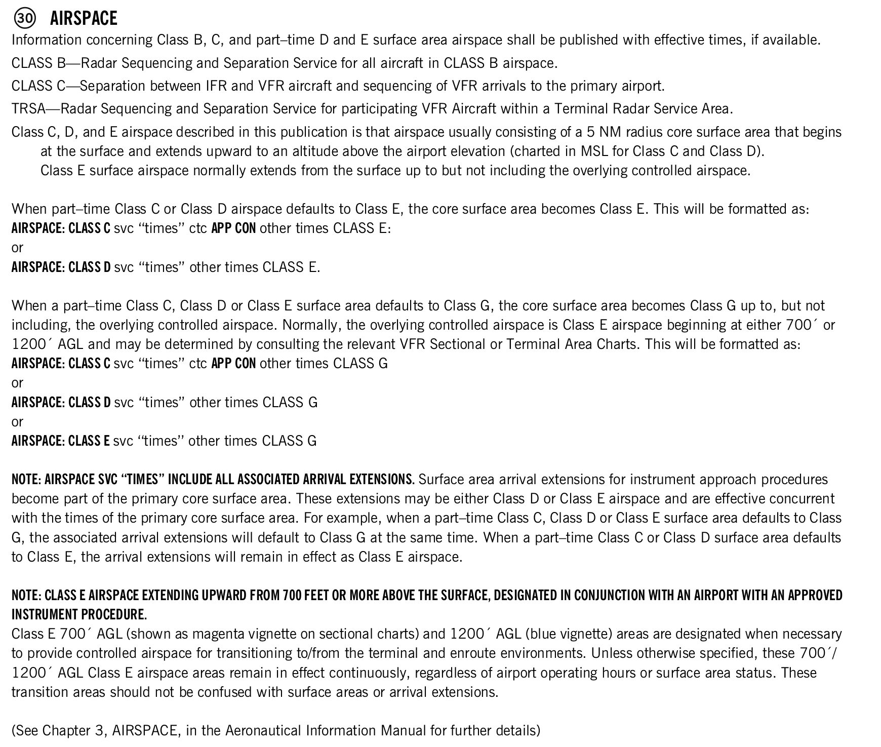
Information concerning Class B, C, and part–time D and E surface area airspace shall be published with effective times, if available.
CLASS B—Radar Sequencing and Separation Service for all aircraft in CLASS B airspace.
CLASS C—Separation between IFR and VFR aircraft and sequencing of VFR arrivals to the primary airport.
TRSA—Radar Sequencing and Separation Service for participating VFR Aircraft within a Terminal Radar Service Area.
Class C, D, and E airspace described in this publication is that airspace usually consisting of a 5 NM radius core surface area that begins at the surface and extends upward to an altitude above the airport elevation (charted in MSL for Class C and Class D). Class E surface airspace normally extends from the surface up to but not including the overlying controlled airspace.
When part–time Class C or Class D airspace defaults to Class E, the core surface area becomes Class E. This will be formatted as: AIRSPACE: CLASS C svc “times” ctc APP CON other times CLASS E:
or
AIRSPACE: CLASS D svc “times” other times CLASS E.
When a part–time Class C, Class D or Class E surface area defaults to Class G, the core surface area becomes Class G up to, but not including, the overlying controlled airspace. Normally, the overlying controlled airspace is Class E airspace beginning at either 700′ or 1200′ AGL and may be determined by consulting the relevant VFR Sectional or Terminal Area Charts. This will be formatted as: AIRSPACE: CLASS C svc “times” ctc APP CON other times CLASS G or
AIRSPACE: CLASS D svc “times” other times CLASS G or
AIRSPACE: CLASS E svc “times” other times CLASS G
NOTE: AIRSPACE SVC “TIMES” INCLUDE ALL ASSOCIATED ARRIVAL EXTENSIONS. Surface area arrival extensions for instrument approach procedures become part of the primary core surface area. These extensions may be either Class D or Class E airspace and are effective concurrent with the times of the primary core surface area. For example, when a part–time Class C, Class D or Class E surface area defaults to Class G, the associated arrival extensions will default to Class G at the same time. When a part–time Class C or Class D surface area defaults to Class E, the arrival extensions will remain in effect as Class E airspace.
NOTE: CLASS E AIRSPACE EXTENDING UPWARD FROM 700 FEET OR MORE ABOVE THE SURFACE, DESIGNATED IN CONJUNCTION WITH AN AIRPORT WITH AN APPROVED
INSTRUMENT PROCEDURE.
Class E 700′ AGL (shown as magenta vignette on sectional charts) and 1200′ AGL (blue vignette) areas are designated when necessary to provide controlled airspace for transitioning to/from the terminal and enroute environments. Unless otherwise specified, these 700′/ 1200′ AGL Class E airspace areas remain in effect continuously, regardless of airport operating hours or surface area status. These transition areas should not be confused with surface areas or arrival extensions.
(See Chapter 3, AIRSPACE, in the Aeronautical Information Manual for further details)
View the FAA printed original (including tables)
31. VOR test facility
FAA Pacific edition, printed page 24–25. Transcribed from the source legend; the printed original is available below.
VOR TEST FACILITY (VOT)
The VOT transmits a signal which provided users a convenient means to determine the operational status and accuracy of an aircraft VOR receiver while on the ground. Ground based VOTs and the associated frequency shall be shown when available. VOTs are also shown with identifier, frequency and referenced remarks in the VOR Receiver Check section in the back of this publication.
View the FAA printed original (including tables)

32. Radio aids to navigation
FAA Pacific edition, printed page 25–28. Transcribed from the source legend; the printed original is available below.
The Airport/Facility Directory section of the Chart Supplement lists, by facility name, all Radio Aids to Navigation that appear on FAA, Aeronautical Information Services Visual or IFR Aeronautical Charts and those upon which the FAA has approved an Instrument Approach Procedure, with exception of selected TACANs. All VOR, VORTAC, TACAN and ILS equipment in the National Airspace System has an automatic monitoring and shutdown feature in the event of malfunction. Unmonitored, as used in this publication, for any navigational aid, means that monitoring personnel cannot observe the malfunction or shutdown signal. The NAVAID NOTAM file identifier will be shown as ‘NOTAM FILE IAD’ and will be listed on the Radio Aids to Navigation line. When two or more NAVAIDS are listed and the NOTAM file identifier is different from that shown on the Radio Aids to Navigation line, it will be shown with the NAVAID listing. NOTAM file identifiers for ILSs and its components (e.g., NDB (LOM) are the same as the associated airports and are not repeated. Automated Surface Observing System (ASOS) and Automated Weather Observing System (AWOS) will be shown when this service is broadcast over selected NAVAIDs.
NAVAID information is tabulated as indicated in the following sample:
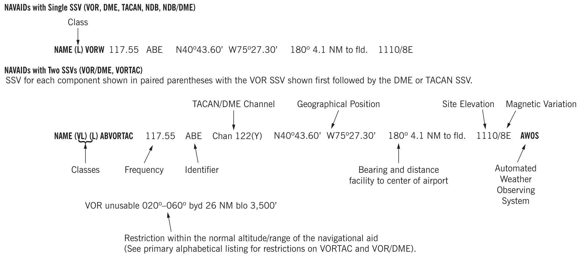
Note: Those DME channel numbers with a (Y) suffix require TACAN to be placed in the ‘Y’ mode to receive distance information.
ASR/PAR—Indicates that Surveillance (ASR) or Precision (PAR) radar instrument approach minimums are published in the U.S. Terminal Procedures. Only part–time hours of operation will be shown.
RADIO CLASS DESIGNATIONS
VOR/DME/TACAN Standard Service Volume (SSV) Classifications
| SSV class | Altitudes | Distance (NM) |
|---|---|---|
| (T) Terminal | 1000′ to 12,000′ | 25 |
| (L) Low Altitude | 1000′ to 18,000′ | 40 |
| (H) High Altitude | 1000′ to 14,500′ | 40 |
| (H) High Altitude | 14,500′ to 18,000′ | 100 |
| (H) High Altitude | 18,000′ to 45,000′ | 130 |
| (H) High Altitude | 45,000′ to 60,000′ | 100 |
| (VL) VOR Low | 1000′ to 5,000′ | 40 |
| (VL) VOR Low | 5,000′ to 18,000′ | 70 |
| (VH) VOR High | 1000′ to 5,000′ | 40 |
| (VH) VOR High | 5,000′ to 14,500′ | 70 |
| (VH) VOR High | 14,500′ to 18,000′ | 100 |
| (VH) VOR High | 18,000′ to 45,000′ | 130 |
| (VH) VOR High | 45,000′ to 60,000′ | 100 |
| (DL) DME Low & (DH) DME High* | 1000′ to 12,900′ | 40 increasing to 130 |
| (DL) DME Low | 12,900′ to 18,000′ | 130 |
| (DH) DME High | 12,900′ to 45,000′ | 130 |
| (DH) DME High | 45,000′ to 60,000′ | 100 |
| *Between 1000′ to 12,900′, DME service volume follows a parabolic curve used by flight management computers. |
NOTES: Additionally, High Altitude facilities provide Low Altitude and Terminal service volume and Low Altitude facilities provide Terminal service volume. Altitudes are with respect to the station's site elevation. Coverage is not available in a cone of airspace directly above the facility. In some cases local conditions (terrain, buildings, trees, etc.) may require that the service volume be restricted. The public shall be informed of any such restriction by a remark in the NAVAID entry in this publication or by a Notice to Airmen (NOTAM).
The term VOR is, operationally, a general term covering the VHF omnidirectional bearing type of facility without regard to the fact that the power, the frequency protected service volume, the equipment configuration, and operational requirements may vary between facilities at different locations.
| Code | Meaning |
|---|---|
| AB | Automatic Weather Broadcast. |
| DF | Direction Finding Service. |
| DME | UHF standard (TACAN compatible) distance measuring equipment. |
| DME(Y) | UHF standard (TACAN compatible) distance measuring equipment that require TACAN to be placed in the ‘Y’ mode to receive DME. |
| GS | Glide slope. |
| H | Non–directional radio beacon (homing), power 50 watts to less than 2,000 watts (50 NM at all altitudes). |
| HH | Non–directional radio beacon (homing), power 2,000 watts or more (75 NM at all altitudes). |
| H–SAB | Non–directional radio beacons providing automatic transcribed weather service. |
| ILS | Instrument Landing System (voice, where available, on localizer channel). |
| IM | Inner marker. |
| LDA | Localizer Directional Aid. |
| LMM | Compass locator station when installed at middle marker site (15 NM at all altitudes). |
| LOM | Compass locator station when installed at outer marker site (15 NM at all altitudes). |
| MH | Non–directional radio beacon (homing) power less than 50 watts (25 NM at all altitudes). |
| MM | Middle marker. |
| OM | Outer marker. |
| S | Simultaneous range homing signal and/or voice. |
| SABH | Non–directional radio beacon not authorized for IFR or ATC. Provides automatic weather broadcasts. |
| SDF | Simplified Direction Facility. |
| TACAN | UHF navigational facility–omnidirectional course and distance information. |
| VOR | VHF navigational facility–omnidirectional course only. |
| VOR/DME | Collocated VOR navigational facility and UHF standard distance measuring equipment. |
| VORTAC | Collocated VOR and TACAN navigational facilities. |
| W | Without voice on radio facility frequency. |
| Z | VHF station location marker at a LF radio facility. |
ILS FACILITY PERFORMANCE CLASSIFICATION CODES
Codes define the ability of an ILS to support autoland operations. The two portions of the code represent Official Category and farthest point along a Category I, II, or III approach that the Localizer meets Category III structure tolerances.
Official Category: I, II, or III; the lowest minima on published or unpublished procedures supported by the ILS.
Farthest point of satisfactory Category III Localizer performance for Category I, II, or III approaches: A – 4 NM prior to runway threshold, B – 3500 ft prior to runway threshold, C – glide angle dependent but generally 750–1000 ft prior to threshold, T – runway threshold, D – 3000 ft after runway threshold, and E – 2000 ft prior to stop end of runway.
ILS information is tabulated as indicated in the following sample:

| VHF frequency | TACAN channel |
|---|---|
| 108.10 | 18X |
| 108.30 | 20X |
| 108.50 | 22X |
| 108.70 | 24X |
| 108.90 | 26X |
| 109.10 | 28X |
| 109.30 | 30X |
| 109.50 | 32X |
| 109.70 | 34X |
| 109.90 | 36X |
| 110.10 | 38X |
| 110.30 | 40X |
| 110.50 | 42X |
| 110.70 | 44X |
| 110.90 | 46X |
| 111.10 | 48X |
| 111.30 | 50X |
| 111.50 | 52X |
| 111.70 | 54X |
| 111.90 | 56X |
| 108.05 | 17Y |
| 108.15 | 18Y |
| 108.25 | 19Y |
| 108.35 | 20Y |
| 108.45 | 21Y |
| 108.55 | 22Y |
| 108.65 | 23Y |
| 108.75 | 24Y |
| 108.85 | 25Y |
| 108.95 | 26Y |
| 109.05 | 27Y |
| 109.15 | 28Y |
| 109.25 | 29Y |
| 109.35 | 30Y |
| 109.45 | 31Y |
| 109.55 | 32Y |
| 109.65 | 33Y |
| 109.75 | 34Y |
| 109.85 | 35Y |
| 109.95 | 36Y |
| 110.05 | 37Y |
| 110.15 | 38Y |
| 110.25 | 39Y |
| 110.35 | 40Y |
| 110.45 | 41Y |
| 110.55 | 42Y |
| 110.65 | 43Y |
| 110.75 | 44Y |
| 110.85 | 45Y |
| 110.95 | 46Y |
| 111.05 | 47Y |
| 111.15 | 48Y |
| 111.25 | 49Y |
| 111.35 | 50Y |
| 111.45 | 51Y |
| 111.55 | 52Y |
| 111.65 | 53Y |
| 111.75 | 54Y |
| 111.85 | 55Y |
| 111.95 | 56Y |
| 113.35 | 80Y |
| 113.45 | 81Y |
| 113.55 | 82Y |
| 113.65 | 83Y |
| 113.75 | 84Y |
| 113.85 | 85Y |
| 113.95 | 86Y |
| 114.05 | 87Y |
| 114.15 | 88Y |
| 114.25 | 89Y |
| 114.35 | 90Y |
| 114.45 | 91Y |
| 114.55 | 92Y |
| 114.65 | 93Y |
| 114.75 | 94Y |
| 114.85 | 95Y |
| 114.95 | 96Y |
| 115.05 | 97Y |
| 115.15 | 98Y |
| 115.25 | 99Y |
| 115.35 | 100Y |
| 115.45 | 101Y |
| 115.55 | 102Y |
| 115.65 | 103Y |
| 115.75 | 104Y |
| 115.85 | 105Y |
| 115.95 | 106Y |
| 116.05 | 107Y |
| 116.15 | 108Y |
| 116.25 | 109Y |
| 116.35 | 110Y |
| 116.45 | 111Y |
| 116.55 | 112Y |
| 116.65 | 113Y |
| 116.75 | 114Y |
| 116.85 | 115Y |
| 116.95 | 116Y |
| 117.05 | 117Y |
| 117.15 | 118Y |
| 117.25 | 119Y |
FREQUENCY PAIRING TABLE
The following is a list of paired VOR/ILS VHF frequencies with TACAN channels.
| TACAN channel | VHF frequency |
|---|---|
| 2X | 134.50 |
| 2Y | 134.55 |
| 11X | 135.40 |
| 11Y | 135.45 |
| 12X | 135.50 |
| 12Y | 135.55 |
| 17X | 108.00 |
| 17Y | 108.05 |
| 18X | 108.10 |
| 18Y | 108.15 |
| 19X | 108.20 |
| 19Y | 108.25 |
| 20X | 108.30 |
| 20Y | 108.35 |
| 21X | 108.40 |
| 21Y | 108.45 |
| 22X | 108.50 |
| 22Y | 108.55 |
| 23X | 108.60 |
| 23Y | 108.65 |
| 24X | 108.70 |
| 24Y | 108.75 |
| 25X | 108.80 |
| 25Y | 108.85 |
| 26X | 108.90 |
| 26Y | 108.95 |
| 27X | 109.00 |
| 27Y | 109.05 |
| 28X | 109.10 |
| 28Y | 109.15 |
| 29X | 109.20 |
| 29Y | 109.25 |
| 30X | 109.30 |
| 30Y | 109.35 |
| 31X | 109.40 |
| 31Y | 109.45 |
| 32X | 109.50 |
| 32Y | 109.55 |
| 33X | 109.60 |
| 33Y | 109.65 |
| 34X | 109.70 |
| 34Y | 109.75 |
| 35X | 109.80 |
| 35Y | 109.85 |
| 36X | 109.90 |
| 36Y | 109.95 |
| 37X | 110.00 |
| 37Y | 110.05 |
| 38X | 110.10 |
| 38Y | 110.15 |
| 39X | 110.20 |
| 39Y | 110.25 |
| 40X | 110.30 |
| 40Y | 110.35 |
| 41X | 110.40 |
| 41Y | 110.45 |
| 42X | 110.50 |
| 42Y | 110.55 |
| 43X | 110.60 |
| 43Y | 110.65 |
| 44X | 110.70 |
| 44Y | 110.75 |
| 45X | 110.80 |
| 45Y | 110.85 |
| 46X | 110.90 |
| 46Y | 110.95 |
| 47X | 111.00 |
| 47Y | 111.05 |
| 48X | 111.10 |
| 48Y | 111.15 |
| 49X | 111.20 |
| 49Y | 111.25 |
| 50X | 111.30 |
| 50Y | 111.35 |
| 51X | 111.40 |
| 51Y | 111.45 |
| 52X | 111.50 |
| 52Y | 111.55 |
| 53X | 111.60 |
| 53Y | 111.65 |
| 54X | 111.70 |
| 54Y | 111.75 |
| 55X | 111.80 |
| 55Y | 111.85 |
| 56X | 111.90 |
| 56Y | 111.95 |
| 57X | 112.00 |
| 57Y | 112.05 |
| 58X | 112.10 |
| 58Y | 112.15 |
| 59X | 112.20 |
| 59Y | 112.25 |
| 60X | 133.30 |
| 60Y | 133.35 |
| 61X | 133.40 |
| 61Y | 133.45 |
| 62X | 133.50 |
| 62Y | 133.55 |
| 63X | 133.60 |
| 63Y | 133.65 |
| 64X | 133.70 |
| 64Y | 133.75 |
| 65X | 133.80 |
| 65Y | 133.85 |
| 66X | 133.90 |
| 66Y | 133.95 |
| 67X | 134.00 |
| 67Y | 134.05 |
| 68X | 134.10 |
| 68Y | 134.15 |
| 69X | 134.20 |
| 69Y | 134.25 |
| 70X | 112.30 |
| 70Y | 112.35 |
| 71X | 112.40 |
| 71Y | 112.45 |
| 72X | 112.50 |
| 72Y | 112.55 |
| 73X | 112.60 |
| 73Y | 112.65 |
| 74X | 112.70 |
| 74Y | 112.75 |
| 75X | 112.80 |
| 75Y | 112.85 |
| 76X | 112.90 |
| 76Y | 112.95 |
| 77X | 113.00 |
| 77Y | 113.05 |
| 78X | 113.10 |
| 78Y | 113.15 |
| 79X | 113.20 |
| 79Y | 113.25 |
| 80X | 113.30 |
| 80Y | 113.35 |
| 81X | 133.40 |
| 81Y | 113.45 |
| 82X | 113.50 |
| 82Y | 113.55 |
| 83X | 113.60 |
| 83Y | 113.65 |
| 84X | 113.70 |
| 84Y | 113.75 |
| 85X | 113.80 |
| 85Y | 113.85 |
| 86X | 113.90 |
| 86Y | 113.95 |
| 87X | 114.00 |
| 87Y | 114.05 |
| 88X | 114.10 |
| 88Y | 114.15 |
| 89X | 114.20 |
| 89Y | 114.25 |
| 90X | 114.30 |
| 90Y | 114.35 |
| 91X | 114.40 |
| 91Y | 114.45 |
| 92X | 114.50 |
| 92Y | 114.55 |
| 93X | 114.60 |
| 93Y | 114.65 |
| 94X | 114.70 |
| 94Y | 114.75 |
| 95X | 114.80 |
| 95Y | 114.85 |
| 96X | 114.90 |
| 96Y | 114.95 |
| 97X | 115.00 |
| 97Y | 115.05 |
| 98X | 115.10 |
| 98Y | 115.15 |
| 99X | 115.20 |
| 99Y | 115.25 |
| 100X | 115.30 |
| 100Y | 115.35 |
| 101X | 115.40 |
| 101Y | 115.45 |
| 102X | 115.50 |
| 102Y | 115.55 |
| 103X | 115.60 |
| 103Y | 115.65 |
| 104X | 115.70 |
| 104Y | 115.75 |
| 105X | 115.80 |
| 105Y | 115.85 |
| 106X | 115.90 |
| 106Y | 115.95 |
| 107X | 116.00 |
| 107Y | 116.05 |
| 108X | 116.10 |
| 108Y | 116.15 |
| 109X | 116.20 |
| 109Y | 116.25 |
| 110X | 116.30 |
| 110Y | 116.35 |
| 111X | 116.40 |
| 111Y | 116.45 |
| 112X | 116.50 |
| 112Y | 116.55 |
| 113X | 116.60 |
| 113Y | 116.65 |
| 114X | 116.70 |
| 114Y | 116.75 |
| 115X | 116.80 |
| 115Y | 116.85 |
| 116X | 116.90 |
| 116Y | 116.95 |
| 117X | 117.00 |
| 117Y | 117.05 |
| 118X | 117.10 |
| 118Y | 117.15 |
| 119X | 117.20 |
| 119Y | 117.25 |
| 120X | 117.30 |
| 120Y | 117.35 |
| 121X | 117.40 |
| 121Y | 117.45 |
| 122X | 117.50 |
| 122Y | 117.55 |
| 123X | 117.60 |
| 123Y | 117.65 |
| 124X | 117.70 |
| 124Y | 117.75 |
| 125X | 117.80 |
| 125Y | 117.85 |
| 126X | 117.90 |
| 126Y | 117.95 |
View the FAA printed original (including tables)
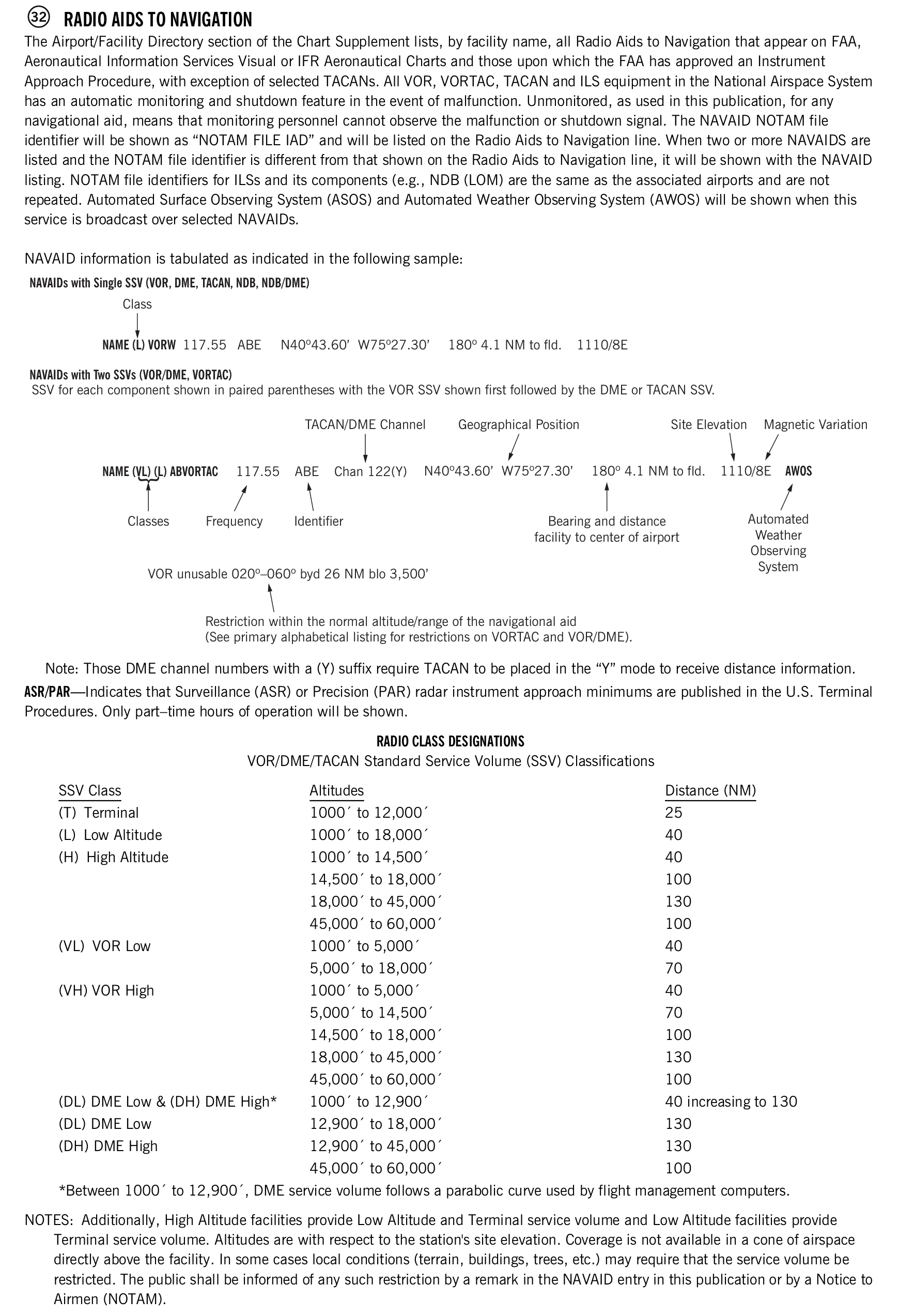
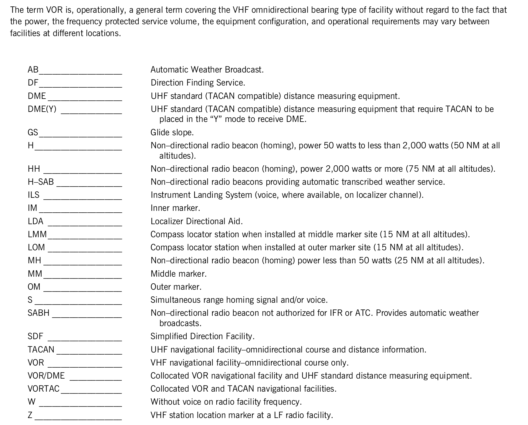
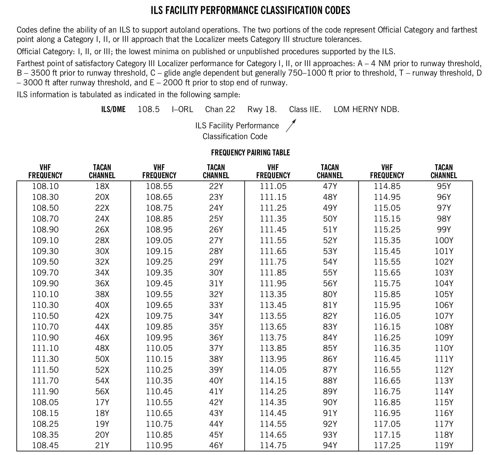
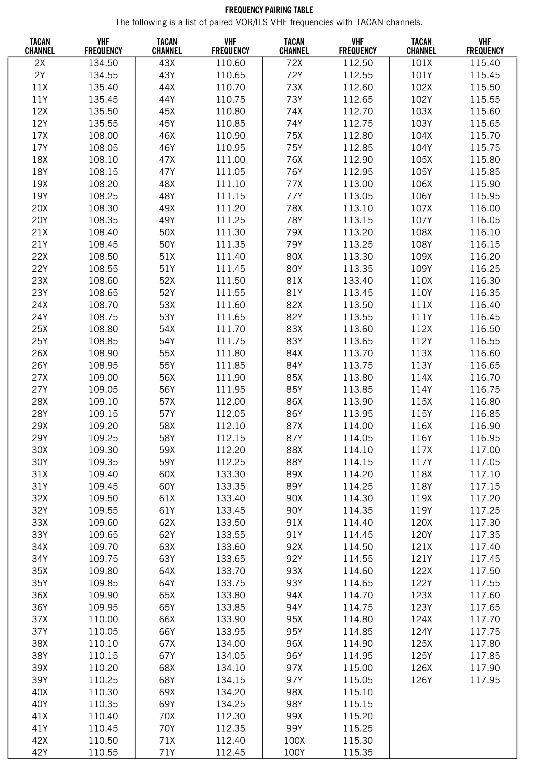
33. COMM/NAV/weather remarks
FAA Pacific edition, printed page 28. Transcribed from the source legend; the printed original is available below.
COMM/NAV/WEATHER REMARKS: These remarks consist of pertinent information affecting the current status of communications, NAVAIDs, weather, and in the absence of air-ground radio outlets identified in the Communications section some approach control facilities will have a clearance delivery phone number listed here.
View the FAA printed original (including tables)

City/Military Airport Cross Reference
- Military airports are listed alphabetically by state and official airport name
- The city/military airport cross-reference listing provides alphabetical listing by state and city name for all military airports published in the directory
Seaplane Landing Areas
- Seaplane landing areas list out the locations of waterways for the locations covered by that volume. []

Special Notices
- Special notices list out airports and airspace which have specific restrictions or programs associated that make them unique
- Topics include aerobatic areas, unmanned aircraft systems operation and LASER light demonstrations to name a few. []
-
Noise Abatement Procedures:
- Airport proprietors are responsible for taking the lead in local aviation noise control.
- Airport proprietors may propose specific noise abatement plans to the FAA.
- If approved, these plans are applied in the form of Formal or Informal Runway Use Programs for noise abatement purposes.
- Noise abatement procedures are listed in special notices which dictate areas to avoid and altitudes to maintain
- Noise abatement procedures are also listed in the airport remarks, abbreviated NS ABTMT

Regulatory Notices
- Regulatory Notices The following narratives summarize the FAR (Federal Aviation Regulations) Part 93 Special Air Traffic Rules, and Airport Traffic Patterns in effect as prescribed in the rule. This information is advisory in nature and in no way relieves the pilot from compliance with the specific rules set forth in FAR Parts 91 and 93
- Special Airport Traffic Areas prescribed in Part 93 are depicted on Sectional Aeronautical Charts, World Aeronautical Charts, Enroute Low Altitude Charts, and where applicable, on VFR Terminal Area Charts
FAA and NWS Telephone Numbers
- FAA and NWS Telephone numbers
Air Route Traffic Control Centers/Flight Service Station Communication Frequencies
Preferred IFR Routes
- Preferred IFR (Instrument Flight Rules) routes are used to best control the flow of traffic on popular routes. []
- To find preferred routes you may also check the FAA's website at: https://www.fly.faa.gov/rmt/nfdc_preferred_routes_database.jsp.
- To learn more, visit the airways and route courses page

VOR Receiver Check
Parachute Jumping Areas
Aeronautical Chart Bulletin
- Aeronautical Chart Bulletin
Land and Hold Short Operations
Airport Diagrams
- Airport Diagrams - updates to aeronautical information
- In support of the Federal Aviation Administration's Runway Incursion Program, selected towered airport diagrams have been published in the Airport Diagram section of the Chart Supplement U.S. Diagrams will be listed alphabetically by associated city and airport name. Airport diagrams, depicting runway and taxiway configurations, will assist both VFR and IFR pilots in ground taxi operations. The airport diagrams in this publication are the same as those published in the U.S. Terminal Procedures Publications. For additional airport diagram legend information see the U.S. Terminal Procedures Publication
- NOTE: Some text data published under the individual airport in the front portion of the Chart Supplement U.S. may be more current than the data published on the Airport Diagrams. The airport diagrams are updated only when significant changes occur
Explore Airport Diagrams and Sketches
Hover over or tap an outlined feature to explore it. Select a topic from the list for an easier target on a small screen.
FAA Pacific source, PDF page 163. Edition: 3 September–29 October 2026. This is an instructional snapshot, not current operational information.
Find it in the sample
Select Start practice, then choose the matching feature.
- Find the runway and pavement surface symbols.
- Find the nonmovement-area symbol.
- Find the arresting-system legend.
- Find the displaced-threshold symbol.
- Find the hot-spot symbol.
- Find runway holding position markings.
- Find self-serve fuel.
- Find the runway-dimensions example.
- Find EMAS in the example sketch.
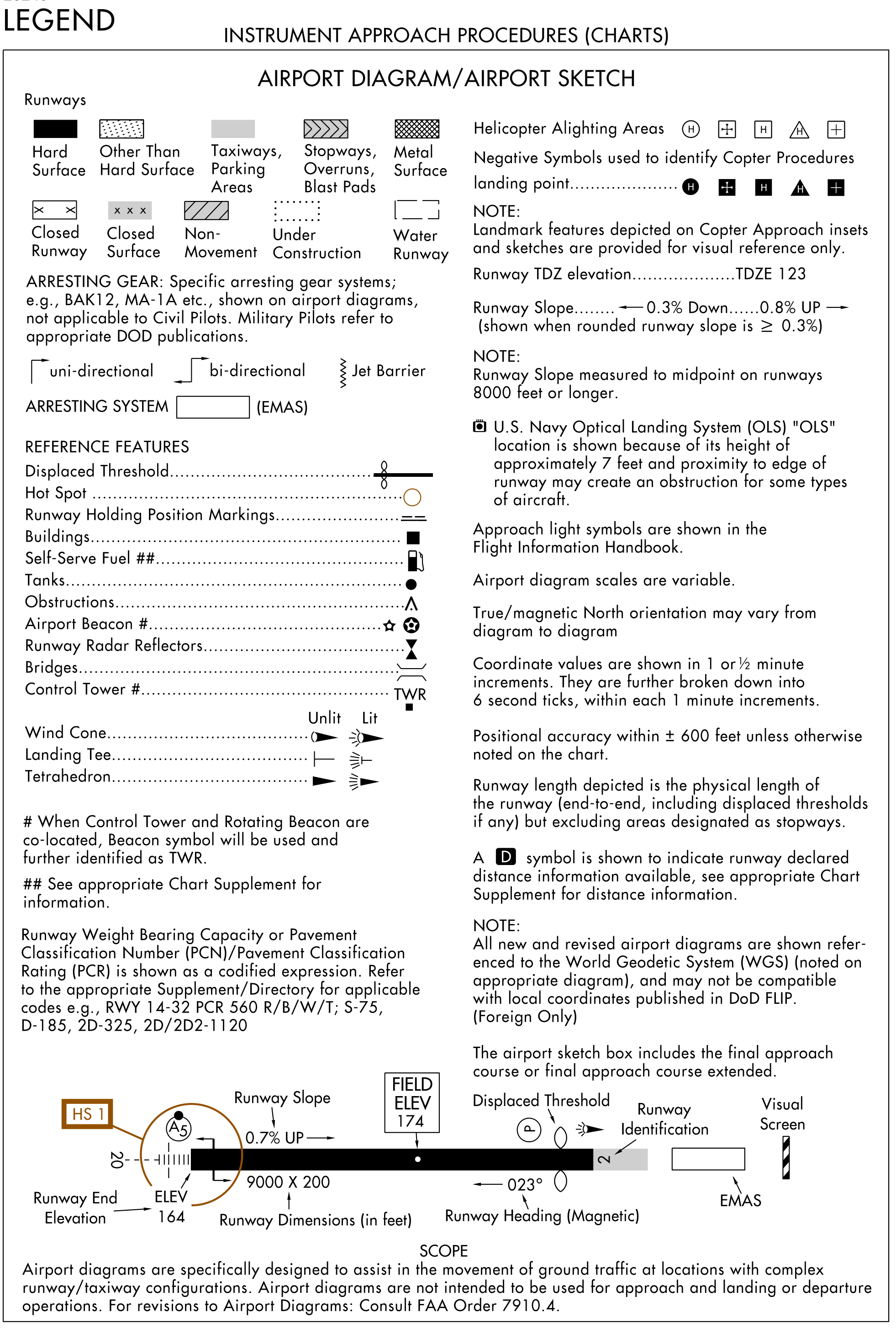
Read all 20 explanations
Runway and pavement surfaces
The legend distinguishes hard-surface, other-than-hard-surface, metal-surface, and water runways. Taxiways and parking areas have their own shading. Stopways, overruns, and blast pads use a separate pattern; they are not part of the depicted physical runway length.
Closed, nonmovement, and construction areas
Separate symbols identify a closed runway, a closed surface, a nonmovement area, and an area under construction. Match the pattern, not just its color, to the legend.
Arresting gear and EMAS
The legend shows unidirectional and bidirectional arresting gear, a jet barrier, and an Engineered Materials Arresting System (EMAS). The FAA notes that specific military arresting-gear systems such as BAK12 and MA-1A are not applicable to civil pilots; military pilots refer to the appropriate Department of Defense publications.
Displaced threshold
The illustrated threshold is displaced from the physical runway end. The FAA diagram legend measures depicted runway length from physical end to end, including any displaced thresholds, but excluding areas designated as stopways.
Hot spot
An open circle or polygon identifies a hot spot. Its HS number connects the location to the published hot-spot description. The Kahului exercise below pairs three of these locations with their FAA descriptions.
Runway holding position markings
This symbol locates runway holding position markings on the airport diagram. The legend identifies the marking; the marking and any applicable clearance must be evaluated at the actual airport.
Buildings and self-serve fuel
The legend uses a filled square for buildings and a fuel-pump symbol for self-serve fuel. The FAA directs readers to the appropriate Chart Supplement for fuel information.
Tanks, obstructions, beacon, reflectors, and bridges
The symbols distinguish tanks, obstructions, an airport beacon, runway radar reflectors, and bridges. When a control tower and rotating beacon are co-located, the beacon symbol is used and further identified as TWR.
Control tower and wind indicators
TWR identifies a control tower. The legend shows unlit and lit wind cones, landing tees, and tetrahedrons. When a tower and rotating beacon are co-located, the beacon symbol is used with TWR.
Runway weight-bearing capacity
Runway weight-bearing capacity, Pavement Classification Number (PCN), or Pavement Classification Rating (PCR) is shown as a coded expression. The FAA directs readers to the applicable Supplement/Directory for the codes. The printed example reads “RWY 14-32 PCR 560 R/B/W/T; S-75, D-185, 2D-325, 2D/2D2-110.”
Helicopter alighting areas
The legend shows helicopter alighting-area symbols. Filled, negative versions identify landing points for helicopter procedures. Landmark features on helicopter approach insets and sketches are provided for visual reference only.
Touchdown-zone elevation and runway slope
TDZE identifies touchdown-zone elevation. Runway slope is shown when the rounded value is 0.3% or greater. On runways 8,000 feet or longer, runway slope is measured to the midpoint.
Optical landing system
The U.S. Navy Optical Landing System (OLS) is shown because its approximately seven-foot height and proximity to the runway edge may create an obstruction for some aircraft.
Scale, north, coordinates, and accuracy
Airport diagram scales are variable, and true/magnetic north orientation may vary from diagram to diagram. Coordinate values are shown in one-minute or half-minute increments, further divided into six-second ticks. The legend gives positional accuracy as ±600 feet unless otherwise noted. New and revised diagrams are referenced to the World Geodetic System (WGS), noted on the diagram; they may not be compatible with local coordinates in Department of Defense Flight Information Publications for foreign locations.
Runway length and declared distances
Depicted runway length is physical end to physical end, including displaced thresholds, excluding stopways. A boxed D indicates that declared-distance information is available in the appropriate Chart Supplement. The airport sketch box includes the final approach course or its extension.
Runway-end and field elevations
In this FAA illustrative sketch, the runway-end elevation is 164 feet and field elevation is 174 feet. These are separate labels; the sketch is not a current airport entry.
Runway dimensions
The example “9000 × 200” gives runway length and width in feet: 9,000 feet long and 200 feet wide.
Magnetic runway heading and identification
The sketch labels the magnetic runway heading as 023° and the runway identification as 2. The heading and runway number are related but are not written at the same precision.
EMAS at the runway end
The outlined rectangle beyond the runway end is labeled EMAS, the Engineered Materials Arresting System. It has its own symbol and is not included in depicted runway length.
Purpose of an airport diagram
The FAA states that airport diagrams assist the movement of ground traffic at locations with complex runway/taxiway configurations. They are not intended for approach, landing, or departure operations. The legend refers revisions to FAA Order 7910.4.
Explore Approach Lighting Systems
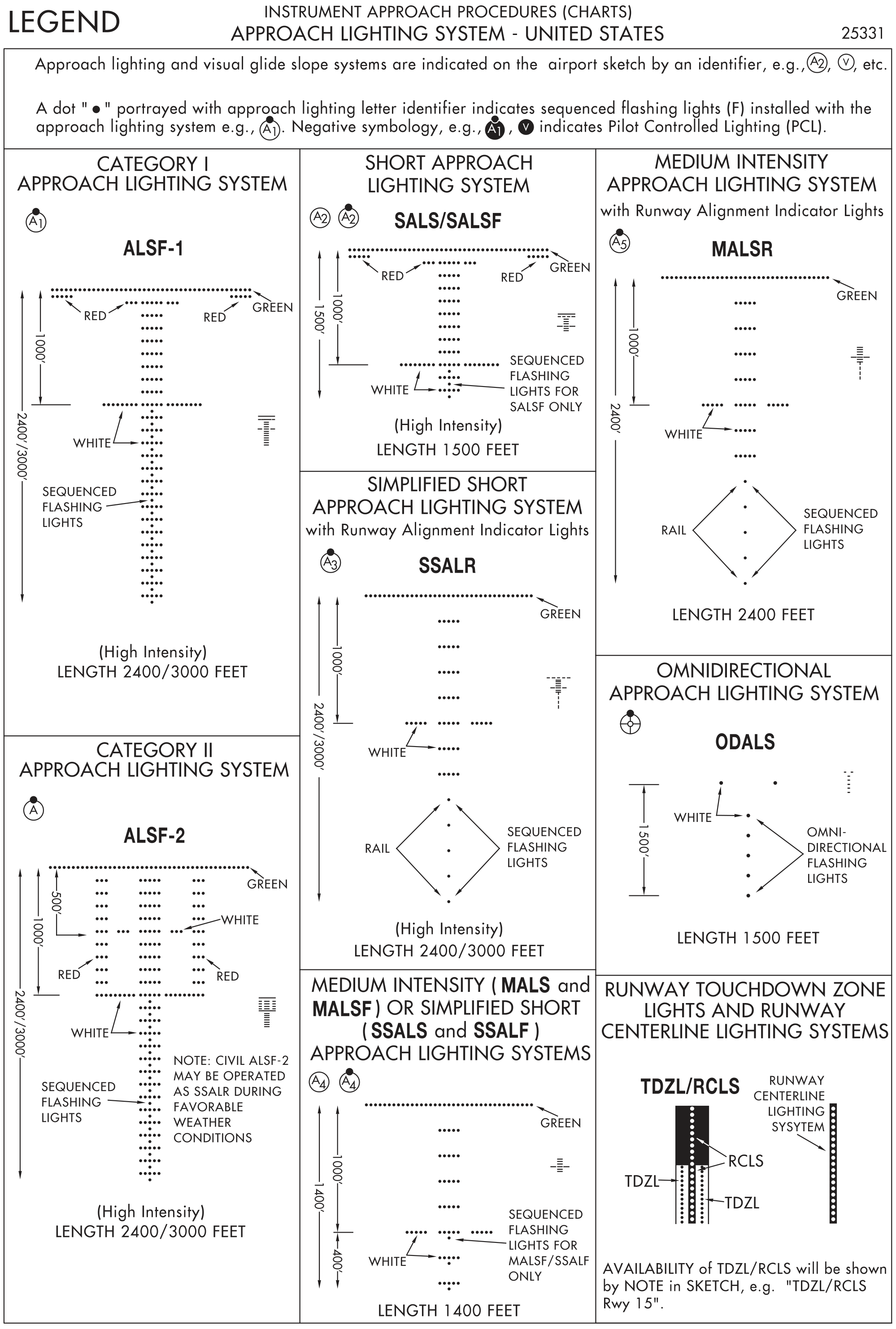
Hover over or tap an outlined feature to explore it. Select a topic from the list for an easier target on a small screen.
FAA Pacific source, PDF page 164. Edition: 3 September–29 October 2026. This is an instructional snapshot, not current operational information.
Find it in the sample
Select Start practice, then choose the matching feature.
- Find the Category I ALSF-1 system.
- Find the Category II system with the additional red side-row bars.
- Find the high-intensity simplified short system with runway alignment indicator lights.
- Find the medium-intensity system with runway alignment indicator lights.
- Find the omnidirectional approach lighting system.
Read all 9 explanations
Chart identifiers and pilot-controlled lighting
Approach lighting and visual glide-slope systems appear on the airport sketch with identifiers. A dot above the approach-lighting letter identifier indicates sequenced flashing lights. A filled, negative identifier indicates Pilot-Controlled Lighting (PCL).
ALSF-1 — Category I
The Category I high-intensity Approach Lighting System with Sequenced Flashing Lights (ALSF-1) is shown with a length of 2,400 or 3,000 feet. The source diagram identifies the red, green, and white lights and the sequenced flashing lights.
ALSF-2 — Category II
The Category II high-intensity Approach Lighting System with Sequenced Flashing Lights (ALSF-2) is shown with a length of 2,400 or 3,000 feet. Compare the additional red side-row bars with ALSF-1. The FAA notes that civil ALSF-2 may operate as a Simplified Short Approach Lighting System with Runway Alignment Indicator Lights (SSALR) during favorable weather conditions.
SALS and SALSF
The Short Approach Lighting System (SALS) and Short Approach Lighting System with Sequenced Flashing Lights (SALSF) are high-intensity systems shown as 1,500 feet long. Sequenced flashing lights apply to SALSF only.
SSALR
The Simplified Short Approach Lighting System with Runway Alignment Indicator Lights (SSALR) is high intensity, 2,400 or 3,000 feet long. The Runway Alignment Indicator Lights (RAIL) are sequenced flashing lights.
MALS / MALSF and SSALS / SSALF
The Medium Intensity Approach Lighting System (MALS), its sequenced-flashing version (MALSF), the Simplified Short Approach Lighting System (SSALS), and its sequenced-flashing version (SSALF) are shown in the same 1,400-foot pattern. Sequenced flashing lights apply to MALSF and SSALF only.
MALSR
The Medium Intensity Approach Lighting System with Runway Alignment Indicator Lights (MALSR) is 2,400 feet long in the legend. Compare its medium-intensity steady lights and sequenced flashing RAIL with the high-intensity SSALR.
ODALS
The Omnidirectional Approach Lighting System (ODALS) is shown as 1,500 feet long. Its white omnidirectional flashing lights differ from the bar patterns of the other systems.
TDZL and RCLS
Touchdown Zone Lights (TDZL) and the Runway Centerline Lighting System (RCLS) are depicted together. Their availability is shown by a note on the airport sketch, such as “TDZL/RCLS Rwy 15.”
Visual Glide-Slope Indicators Simulator
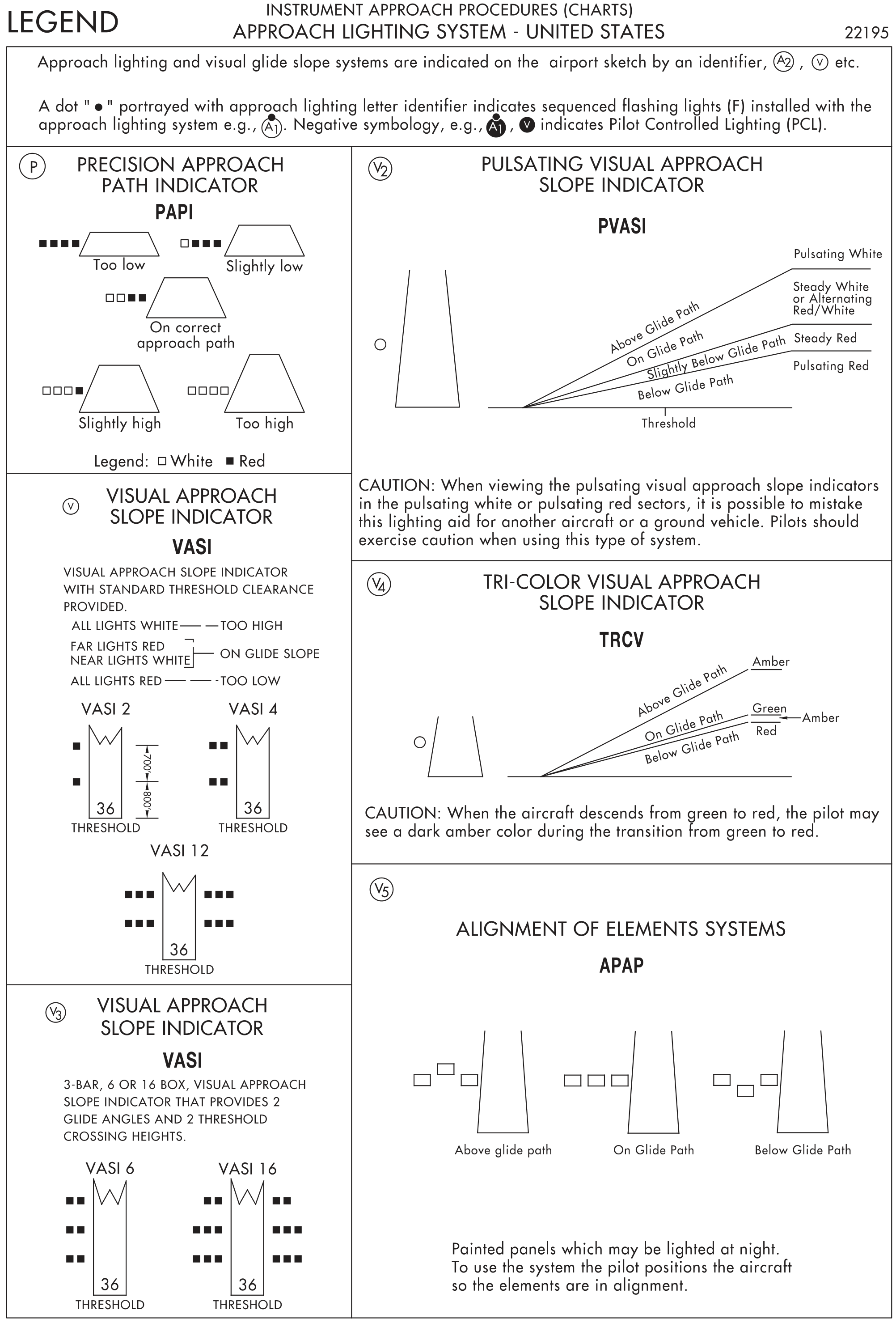
Hover over or tap an outlined feature to explore it. Select a topic from the list for an easier target on a small screen.
FAA Pacific source, PDF page 165. Edition: 3 September–29 October 2026. This is an instructional snapshot, not current operational information.
Try the light indications
Read all 6 explanations
PAPI
The Precision Approach Path Indicator (PAPI) uses four lights. Four red means too low; one white and three red means slightly low; two white and two red means on the correct approach path; three white and one red means slightly high; four white means too high.
Two-bar VASI
For the Visual Approach Slope Indicator (VASI) with standard obstacle clearance provided, all lights white means too high; far lights red and near lights white means on glide slope; all lights red means too low. The legend illustrates two-, four-, and twelve-box installations.
Three-bar VASI
A three-bar Visual Approach Slope Indicator (VASI), with six or sixteen boxes, provides two glide angles and two threshold-crossing heights. The near and middle bars provide the lower path; the middle and far bars provide the upper path, intended only for high-cockpit aircraft.
Pulsating VASI
The Pulsating Visual Approach Slope Indicator (PVASI) shows pulsating white above glide path, steady white or alternating red/white on glide path, steady red slightly below glide path, and pulsating red below glide path. The FAA cautions that pulsating white or red sectors may be mistaken for another aircraft or a ground vehicle.
Tri-color VASI
The Tri-Color Visual Approach Slope Indicator (TRCV) shows amber above glide path, green on glide path, and red below glide path. When descending from green to red, the pilot may see a dark amber color during the transition.
Alignment of elements
The APAP alignment-of-elements system uses painted panels that may be lighted at night. The pilot positions the aircraft so the elements are in alignment. The source illustrates above-, on-, and below-glide-path appearances.
Decode METAR and TAF Weather Reports
Hover over or tap a code group to decode it. Compare an observed METAR with a forecast TAF, then try finding the requested information.
FAA AIM 7–1–28, Key to Aerodrome Forecast (TAF) and Aviation Routine Weather Report (METAR). Instructional examples, not current airport weather.
These are instructional examples from FAA AIM 7–1–28, not live weather. The Pacific supplement’s decoding key uses older TAF time-group formatting; this exercise uses the current AIM’s day/time format. The AIM’s BECMG illustration is retained with an explanation that NWS TAFs do not use that group.
For comparison, view the Pacific edition’s original weather key, printed pages 118–119 (PDF pages 120–121).
Find it in the sample
Select Start practice, then choose the matching feature.
- Find the runway-specific visual range in the METAR.
- Find the sea-level pressure in the METAR remarks.
- Find the beginning and ending validity dates and hours of the TAF.
- Find the forecast nonconvective low-level wind shear.
- Find the group introducing temporary forecast fluctuations.
METAR — observation
TAF — forecast
Read all 45 explanations
METAR report type
METAR identifies an Aviation Routine Weather Report: an observation, rather than a forecast. SPECI identifies a special report.
Station identifier
KPIT identifies Pittsburgh International Airport in this FAA instructional example. Airport identifiers are location identifiers, not weather conditions.
Observation time
091955Z means the observation is for the 9th day of the month at 1955 Coordinated Universal Time (UTC). Z denotes UTC.
Corrected report
COR identifies a corrected observation. AUTO, when present, identifies a fully automated report without human intervention.
Wind
22015G25KT means wind from 220° true at 15 knots, gusting to 25 knots. KT means knots. Forecast wind groups use the same direction, speed, and gust convention; 15005KT is from 150° true at 5 knots. A direction of VRB means variable.
Prevailing visibility
3/4SM means three-quarters of a statute mile of prevailing visibility. SM denotes statute miles. Forecast examples include 5SM, 3SM, 1/2SM, 1SM, and 6SM. P6SM means more than six statute miles.
Runway visual range
R28L/2600FT gives Runway Visual Range (RVR) for Runway 28 Left: 2,600 feet. This is a runway-specific measurement, distinct from prevailing visibility.
Present or forecast weather
TSRA means thunderstorm with rain. SHRA means rain showers; +TSRA means a thunderstorm with heavy rain; -RA means light rain; -SHRA means light rain showers. HZ means haze and BR means mist. A minus sign indicates light intensity, no sign moderate intensity where applicable, and a plus sign heavy intensity.
Sky condition and ceiling
OVC010CB means overcast at 1,000 feet above ground level with cumulonimbus clouds. FEW means few (1–2 eighths), SCT scattered (3–4 eighths), BKN broken (5–7 eighths), and OVC overcast (8 eighths). Heights are in hundreds of feet. FEW020 is few clouds at 2,000 feet; BKN020 OVC040 gives broken at 2,000 and overcast at 4,000 feet. The ceiling is the lowest broken or overcast layer, or vertical visibility into an obscuration. CB identifies cumulonimbus.
Temperature and dew point
18/16 means temperature 18°C and dew point 16°C. A preceding M denotes a negative Celsius temperature.
Altimeter setting
A2992 means an altimeter setting of 29.92 inches of mercury.
Remarks
RMK introduces remarks. The following groups supplement the body of the observation.
Sea-level pressure
SLP045 decodes to sea-level pressure of 1004.5 hectopascals (hPa). The group encodes the last three digits, including tenths; the appropriate 9 or 10 prefix restores a plausible sea-level pressure.
Precise temperature and dew point
T01820159 gives temperature +18.2°C and dew point +15.9°C. Each four-digit group has a sign digit (0 positive, 1 negative) followed by three digits in tenths of a degree.
TAF report type
TAF identifies a Terminal Aerodrome Forecast. It predicts airport weather during a stated validity period. AMD identifies an amended forecast and COR a corrected forecast when present.
Forecast issue time
091730Z means the forecast was issued on the 9th day of the month at 1730 UTC. This is the issue time, not the start of its validity.
Forecast validity
0918/1024 means valid from 1800 UTC on the 9th through 2400 UTC on the 10th (0000 UTC on the 11th), a 30-hour period. The slash separates beginning and ending day/hour groups.
Low-level wind shear
WS010/31022KT forecasts nonconvective low-level wind shear at 1,000 feet above ground level, with wind there from 310° true at 22 knots. It is separate from the surface wind group.
FM — new prevailing conditions
FM091930 introduces a new set of prevailing conditions from 1930 UTC on the 9th. FM100100 begins at 0100 UTC on the 10th, and FM101015 at 1015 UTC on the 10th. FM groups use day, hour, and minute; they are not read as hour-only groups.
TEMPO — temporary fluctuations
TEMPO 0920/0922 forecasts temporary fluctuations between 2000 and 2200 UTC on the 9th. Each fluctuation lasts less than an hour and, in aggregate, occupies less than half of the indicated period. The following groups describe the temporary conditions.
PROB30 — probability
PROB30 1004/1007 gives a 30% probability of the following conditions between 0400 and 0700 UTC on the 10th. The National Weather Service (NWS) does not use PROB groups during the first nine hours of its TAFs.
BECMG — becoming
BECMG 1013/1015 indicates a change during 1300–1500 UTC on the 10th; the exact change time is not specified. The FAA example includes this group to illustrate the code. NWS TAFs do not use BECMG, although it may appear in international and military forecasts.
NSW and SKC
NSW means no significant weather, ending the previously forecast significant weather in the applicable change group. SKC means sky clear. This group belongs to the FAA’s illustrative BECMG portion; it is not an example of NWS BECMG usage.
15005KT — Wind
15005KT: Wind from 150° true at 5 knots.
22015G25KT means wind from 220° true at 15 knots, gusting to 25 knots. KT means knots. Forecast wind groups use the same direction, speed, and gust convention; 15005KT is from 150° true at 5 knots. A direction of VRB means variable.
5SM — Prevailing visibility
5SM: Prevailing visibility five statute miles.
3/4SM means three-quarters of a statute mile of prevailing visibility. SM denotes statute miles. Forecast examples include 5SM, 3SM, 1/2SM, 1SM, and 6SM. P6SM means more than six statute miles.
HZ — Present or forecast weather
HZ: Haze.
TSRA means thunderstorm with rain. SHRA means rain showers; +TSRA means a thunderstorm with heavy rain; -RA means light rain; -SHRA means light rain showers. HZ means haze and BR means mist. A minus sign indicates light intensity, no sign moderate intensity where applicable, and a plus sign heavy intensity.
FEW020 — Sky condition and ceiling
FEW020: Few clouds at 2,000 feet above ground level. A few-cloud layer is not a ceiling.
OVC010CB means overcast at 1,000 feet above ground level with cumulonimbus clouds. FEW means few (1–2 eighths), SCT scattered (3–4 eighths), BKN broken (5–7 eighths), and OVC overcast (8 eighths). Heights are in hundreds of feet. FEW020 is few clouds at 2,000 feet; BKN020 OVC040 gives broken at 2,000 and overcast at 4,000 feet. The ceiling is the lowest broken or overcast layer, or vertical visibility into an obscuration. CB identifies cumulonimbus.
30015G25KT — Wind
30015G25KT: Wind from 300° true at 15 knots, gusting to 25 knots.
22015G25KT means wind from 220° true at 15 knots, gusting to 25 knots. KT means knots. Forecast wind groups use the same direction, speed, and gust convention; 15005KT is from 150° true at 5 knots. A direction of VRB means variable.
3SM — Prevailing visibility
3SM: Prevailing visibility three statute miles.
3/4SM means three-quarters of a statute mile of prevailing visibility. SM denotes statute miles. Forecast examples include 5SM, 3SM, 1/2SM, 1SM, and 6SM. P6SM means more than six statute miles.
SHRA — Present or forecast weather
SHRA: Moderate rain showers.
TSRA means thunderstorm with rain. SHRA means rain showers; +TSRA means a thunderstorm with heavy rain; -RA means light rain; -SHRA means light rain showers. HZ means haze and BR means mist. A minus sign indicates light intensity, no sign moderate intensity where applicable, and a plus sign heavy intensity.
OVC015 — Sky condition and ceiling
OVC015: Overcast at 1,500 feet above ground level; this is the forecast ceiling.
OVC010CB means overcast at 1,000 feet above ground level with cumulonimbus clouds. FEW means few (1–2 eighths), SCT scattered (3–4 eighths), BKN broken (5–7 eighths), and OVC overcast (8 eighths). Heights are in hundreds of feet. FEW020 is few clouds at 2,000 feet; BKN020 OVC040 gives broken at 2,000 and overcast at 4,000 feet. The ceiling is the lowest broken or overcast layer, or vertical visibility into an obscuration. CB identifies cumulonimbus.
1/2SM — Prevailing visibility
1/2SM: Prevailing visibility one-half statute mile.
3/4SM means three-quarters of a statute mile of prevailing visibility. SM denotes statute miles. Forecast examples include 5SM, 3SM, 1/2SM, 1SM, and 6SM. P6SM means more than six statute miles.
+TSRA — Present or forecast weather
+TSRA: Thunderstorm with heavy rain.
TSRA means thunderstorm with rain. SHRA means rain showers; +TSRA means a thunderstorm with heavy rain; -RA means light rain; -SHRA means light rain showers. HZ means haze and BR means mist. A minus sign indicates light intensity, no sign moderate intensity where applicable, and a plus sign heavy intensity.
OVC008CB — Sky condition and ceiling
OVC008CB: Overcast at 800 feet above ground level, with cumulonimbus clouds; the ceiling is 800 feet.
OVC010CB means overcast at 1,000 feet above ground level with cumulonimbus clouds. FEW means few (1–2 eighths), SCT scattered (3–4 eighths), BKN broken (5–7 eighths), and OVC overcast (8 eighths). Heights are in hundreds of feet. FEW020 is few clouds at 2,000 feet; BKN020 OVC040 gives broken at 2,000 and overcast at 4,000 feet. The ceiling is the lowest broken or overcast layer, or vertical visibility into an obscuration. CB identifies cumulonimbus.
FM100100 — FM — new prevailing conditions
FM100100: New prevailing conditions from 0100 UTC on the 10th.
FM091930 introduces a new set of prevailing conditions from 1930 UTC on the 9th. FM100100 begins at 0100 UTC on the 10th, and FM101015 at 1015 UTC on the 10th. FM groups use day, hour, and minute; they are not read as hour-only groups.
27008KT — Wind
27008KT: Wind from 270° true at 8 knots.
22015G25KT means wind from 220° true at 15 knots, gusting to 25 knots. KT means knots. Forecast wind groups use the same direction, speed, and gust convention; 15005KT is from 150° true at 5 knots. A direction of VRB means variable.
BKN020 OVC040 — Sky condition and ceiling
BKN020 OVC040: Broken clouds at 2,000 feet and overcast at 4,000 feet above ground level. The lower broken layer establishes a 2,000-foot ceiling.
OVC010CB means overcast at 1,000 feet above ground level with cumulonimbus clouds. FEW means few (1–2 eighths), SCT scattered (3–4 eighths), BKN broken (5–7 eighths), and OVC overcast (8 eighths). Heights are in hundreds of feet. FEW020 is few clouds at 2,000 feet; BKN020 OVC040 gives broken at 2,000 and overcast at 4,000 feet. The ceiling is the lowest broken or overcast layer, or vertical visibility into an obscuration. CB identifies cumulonimbus.
1SM — Prevailing visibility
1SM: Prevailing visibility one statute mile.
3/4SM means three-quarters of a statute mile of prevailing visibility. SM denotes statute miles. Forecast examples include 5SM, 3SM, 1/2SM, 1SM, and 6SM. P6SM means more than six statute miles.
-RA BR — Present or forecast weather
-RA BR: Light rain and mist.
TSRA means thunderstorm with rain. SHRA means rain showers; +TSRA means a thunderstorm with heavy rain; -RA means light rain; -SHRA means light rain showers. HZ means haze and BR means mist. A minus sign indicates light intensity, no sign moderate intensity where applicable, and a plus sign heavy intensity.
FM101015 — FM — new prevailing conditions
FM101015: New prevailing conditions from 1015 UTC on the 10th.
FM091930 introduces a new set of prevailing conditions from 1930 UTC on the 9th. FM100100 begins at 0100 UTC on the 10th, and FM101015 at 1015 UTC on the 10th. FM groups use day, hour, and minute; they are not read as hour-only groups.
18005KT — Wind
18005KT: Wind from 180° true at 5 knots.
22015G25KT means wind from 220° true at 15 knots, gusting to 25 knots. KT means knots. Forecast wind groups use the same direction, speed, and gust convention; 15005KT is from 150° true at 5 knots. A direction of VRB means variable.
6SM — Prevailing visibility
6SM: Prevailing visibility six statute miles.
3/4SM means three-quarters of a statute mile of prevailing visibility. SM denotes statute miles. Forecast examples include 5SM, 3SM, 1/2SM, 1SM, and 6SM. P6SM means more than six statute miles.
-SHRA — Present or forecast weather
-SHRA: Light rain showers.
TSRA means thunderstorm with rain. SHRA means rain showers; +TSRA means a thunderstorm with heavy rain; -RA means light rain; -SHRA means light rain showers. HZ means haze and BR means mist. A minus sign indicates light intensity, no sign moderate intensity where applicable, and a plus sign heavy intensity.
OVC020 — Sky condition and ceiling
OVC020: Overcast at 2,000 feet above ground level; this is the forecast ceiling.
OVC010CB means overcast at 1,000 feet above ground level with cumulonimbus clouds. FEW means few (1–2 eighths), SCT scattered (3–4 eighths), BKN broken (5–7 eighths), and OVC overcast (8 eighths). Heights are in hundreds of feet. FEW020 is few clouds at 2,000 feet; BKN020 OVC040 gives broken at 2,000 and overcast at 4,000 feet. The ceiling is the lowest broken or overcast layer, or vertical visibility into an obscuration. CB identifies cumulonimbus.
P6SM — Prevailing visibility
P6SM: Prevailing visibility greater than six statute miles.
3/4SM means three-quarters of a statute mile of prevailing visibility. SM denotes statute miles. Forecast examples include 5SM, 3SM, 1/2SM, 1SM, and 6SM. P6SM means more than six statute miles.
Airport Hot Spots
- An airport surface hot spot is a location on an airport movement area with a history or potential risk of collision or runway incursion, where heightened attention by pilots and drivers is necessary.
- It is a runway-safety problem area that presents increased risk during surface operations.
- A hot spot is typically a complex or confusing taxiway/taxiway or taxiway/runway intersection.
- Contributing factors include airport layout, traffic flow, airport markings, signage and lighting, situational awareness, and training.
- Circles or ellipses identify ground-movement hot spots.
- These may involve hold-short line infractions, approach-hold issues, complex taxiways, movement/nonmovement boundaries, tower line-of-sight problems, or marking and signage issues.
- Cylinders identify wrong-surface hot spots.
- These mark locations where aircraft have inadvertently attempted to, or actually did, depart from or land on the wrong surface.
- Labels such as HS 1, HS 2, and HS 3 connect each diagram location to a brief description in the Chart Supplement U.S..
- Read the description on the hot spot table to understand why the location is highlighted.
- Hot spots remain charted until the increased risk has been reduced or eliminated.
- The FAA’s From the Flight Deck videos provide additional airport-specific coverage of hot spots and surface-safety concerns.
- Brief the route: Before taxiing, identify hot spots along the assigned route, the specific hazard at each, and applicable holding positions.
- Check current conditions: Review current airport information, notices, and closures; construction or temporary changes may affect the route.
- Reduce distractions: Keep the diagram available, maintain an outside scan, and postpone nonessential tasks while navigating the hot spot.
- Stop if uncertain: On a taxiway, stop and request clarification from air traffic control if unsure of your position or clearance. Obtain an explicit runway-crossing clearance when operating under tower control.
Reading a hot-spot listing

- HS 1: The sample identifies a complex area, calls for verification of the correct taxi route, and notes that areas south of Taxiways A and G are private ramp.
- HS 2: The sample identifies traffic congestion from the large volume of aircraft proceeding to and from Runway 31.
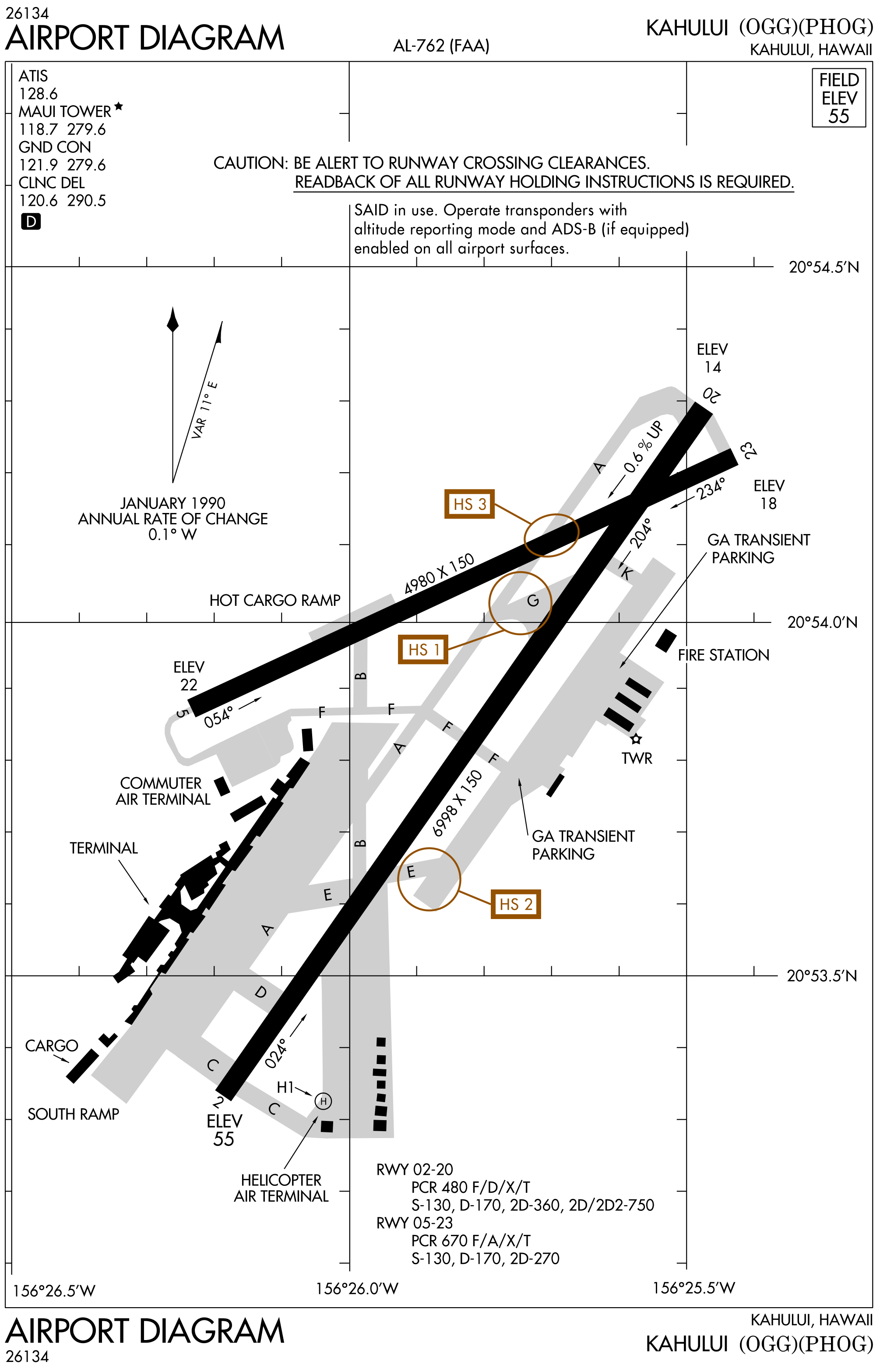
Explore Hot Spots at Kahului (OGG).
- Hover or tap an outlined location.
Read all 3 explanations
HS 1 — Taxiway F versus Taxiway G
FAA description: “Acft ldg Rwy 05 and instructed to exit on Twy A with a left turn onto Twy F to the east ramp, sometimes turn left onto Twy G by mistake.”
In plain language: after landing on Runway 05 and exiting onto Taxiway A, a left turn intended for Taxiway F toward the east ramp can be confused with Taxiway G.
HS 2 — Runway 02–20 holding position
FAA description: “Rwy holding position marking Rwy 02–20 located at the intersection of Twy E and the ramp.”
In plain language: the holding position for Runway 02–20 is at the Taxiway E/ramp intersection. Locate the marking before moving toward the runway.
HS 3 — Crossing Runway 05–23
FAA description: “Acft ldg Rwy 02 that are instructed to exit left on Twy A sometimes cross Rwy 05–23 wo clnc.”
In plain language: aircraft landing on Runway 02 and exiting left onto Taxiway A may cross Runway 05–23 without clearance. Identify the crossing while planning the exit.
Read the FAA hot-spot source excerpt
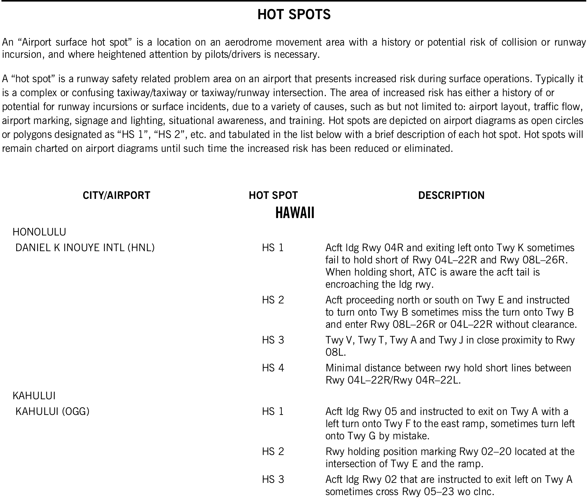
Obtaining a Chart Supplement U.S.
- Copies of the Chart Supplement U.S. can be found in many places in different forms:
- First, you can check with your local Fixed Base Operator (FBO)
- Second, you can purchase a paperback or subscription online [Amazon].
- Third, you can download a digital copy from the FAA's website
- Digital editions of the Chart Supplement U.S. may not include all material found in the hard-copy publications, such as Special Notices or VOR receiver checkpoints.
Chart Supplement U.S. Interactive Scenario
Interactive Scenario
Loading scenario details...
Scenario Complete
Chart Supplement U.S. Knowledge Check
Choose the knowledge check that matches your current training for Chart Supplement U.S..
 Private Pilot
PPL knowledge check
Core Knowledge Review
Review foundational knowledge, key concepts, and practical considerations. Topic: Chart Supplement U.S..
- Immediate feedback
- Answer explanations
- Account progress tracking
 Commercial Pilot
CPL knowledge check
Advanced Application
Apply knowledge to advanced operations, risk management, and aeronautical decision-making. Topic: Chart Supplement U.S..
- Immediate feedback
- Answer explanations
- Account progress tracking
Why Take a Quiz?
Quizzes reinforce key concepts, identify knowledge gaps, and build confidence for real-world decisions. Quiz material is representative of the information provided here and is not based on or sourced from the Federal Aviation Administration test bank.
Chart Supplement, U.S. Conclusion
- Sample Legend and supplemental pages: (Always use the most current publications)
- Airport directory information are also available using the AOPA App
- Still looking for something? Continue searching:
Comments: