Airways & Route Course Change
Airway and Route Course Navigation guide the pilot through a series of highways in the sky to the ultimate destination.
Introduction to Airways & Route Course Change
- Airways are the primary means for routing aircraft operating under IFR.
- Three fixed route systems are established for air navigation purposes:
- The Federal Airway System (consisting of VOR and L/MF routes),.
- The Jet Route System, and;
- The RNAV Route System.
- To the extent possible, these route systems are aligned in an overlying manner to facilitate the transition between each
Airways & Route Course Change Key Highlights
- Airways provide standardized navigation routes that support organized and predictable en route flight operations.
- Victor airways are low-altitude IFR routes based primarily on VOR navigation facilities.
- Jet routes are high-altitude airways used by aircraft operating primarily above 18,000 feet mean sea level.
- RNAV routes use area navigation systems to provide flexible routing independent of ground-based navigation facilities.
- Course changes along airways require pilots to identify navigation fixes, transition points, and proper route sequencing.
- Pilots must monitor navigation equipment carefully to ensure accurate tracking during airway transitions and course changes.
- Wind correction angles and magnetic variation affect aircraft heading requirements while maintaining assigned courses.
- Air traffic control may assign reroutes, direct clearances, or amended routing based on traffic and operational conditions.
- Improper navigation management during course changes can lead to route deviations and loss of situational awareness.
- Understanding airway structure and route course changes improves navigation accuracy, IFR operations, and overall flight safety.
Federal Airway System
- The VOR and L/MF (non-directional radio beacons) Airway System consists of airways designated from 1,200' above the surface (or in some instances higher) up to but not including 18,000' MSL.
- IFR Enroute Low Altitude Charts depict these airways.
- The altitude limits of a victor airway should not be exceeded except to effect transition within or between route structures.
- Federal airways are based on a centerline that extends from one navigational aid (NAVAID)/waypoint/fix/intersection to another NAVAID/waypoint/fix/intersection specified for that airway.
- A Federal airway includes the airspace within parallel boundary lines 4 NM to each side of the centerline.
- The VOR airways are classified as Domestic, Alaskan, and Hawaiian
- As in all instrument flight, courses are magnetic, and distances are in NM.
- Except in Alaska, the VOR airways are:
- Predicated solely on VOR or VORTAC navigation aids;
- Identified by a "V" (Victor) followed by the airway number (for example, V12).
- Typically, Victor airways are given odd numbers when oriented north/south and even numbers when oriented east/west.
- Depicted in black on aeronautical charts;
- Segments of VOR airways in Alaska are based on L/MF navigation aids and charted in brown instead of black on en route charts.
- A segment of an airway which is common to two or more routes carries the numbers of all the airways which coincide for that segment.
- When such is the case, pilots filing a flight plan need to indicate only that airway number for the route filed.
- A pilot who intends to make an airway flight, using VOR facilities, will simply specify the appropriate "victor" airway(s) in the flight plan. For example, if a flight is to be made from Chicago to New Orleans at 8,000 feet, using omniranges only, the route may be indicated as "departing from Chicago-Midway, cruising 8,000 feet via Victor 9 to Moisant International." If flight is to be conducted in part by means of L/MF navigation aids and in part on omniranges, specifications of the appropriate airways in the flight plan will indicate which types of facilities will be used along the described routes, and, for IFR flight, permit ATC to issue a traffic clearance accordingly. A route may also be described by specifying the station over which the flight will pass, but in this case since many VORs and L/MF aids have the same name, the pilot must be careful to indicate which aid will be used at a particular location. This will be indicated in the route of flight portion of the flight plan by specifying the type of facility to be used after the location name in the following manner: Newark L/MF, Allentown VOR
- Pilots must fly the centerline of an airway or a direct route between fixes.
- Inside of 50 NM, the width will extend 4 NM from centerline (8 NM wide)
- Outside of 50 NM, the accuracy of NAVAIDs (4.5° tolerance) will determine the width of the airway
- With respect to position reporting, reporting points are designated for VOR Airway Systems.
- Flights using Victor Airways will report over these points unless advised otherwise by ATC.
- A Federal airway does not include the airspace of a prohibited area.
- Colored Airways:
- The L/MF airways (colored airways) are predicated solely on L/MF navigation aids and are depicted in brown on aeronautical charts and are identified by color name and number (e.g., Amber One).
- Green and Red airways are plotted east and west.
- Amber and Blue airways are plotted north and south.
- The use of TSO-C145 (as revised) or TSO-C146 (as revised) GPS/WAAS navigation systems is allowed in Alaska as the only means of navigation on published air traffic service (ATS) routes, including those Victor, Terminal Transition Routes (T-Routes), and colored airway segments designated with a second minimum en route altitude (MEA) depicted in blue and followed by the letter G at those lower altitudes. The altitudes so depicted are below the minimum reception altitude (MRA) of the land-based navigation facility defining the route segment, and guarantee standard en route obstacle clearance and two-way communications. Air carrier operators requiring operations specifications are authorized to conduct operations on those routes in accordance with FAA operations specifications

Jet Route System
- Similar to the Victor route system, the jet route system consists of jet routes established from 18,000' MSL to FL 450 inclusive.
- These routes are depicted on Enroute High Altitude Charts.
- Depicted in black on aeronautical charts.
- Identified by a "J" (Jet) followed by the airway number (e.g., J12).
- Jet routes, as VOR airways, are predicated solely on VOR or VORTAC navigation facilities (except in Alaska).
- Segments of jet routes in Alaska are based on L/MF navigation aids and are charted in brown color instead of black on en route charts.
- Operation above FL 450 may be conducted on a point-to-point basis.
- Navigational guidance is provided on an area basis utilizing those facilities depicted on the enroute high altitude charts
- With respect to position reporting, reporting points are designated for jet route systems. Flights using jet routes will report over these points unless otherwise advised by ATC
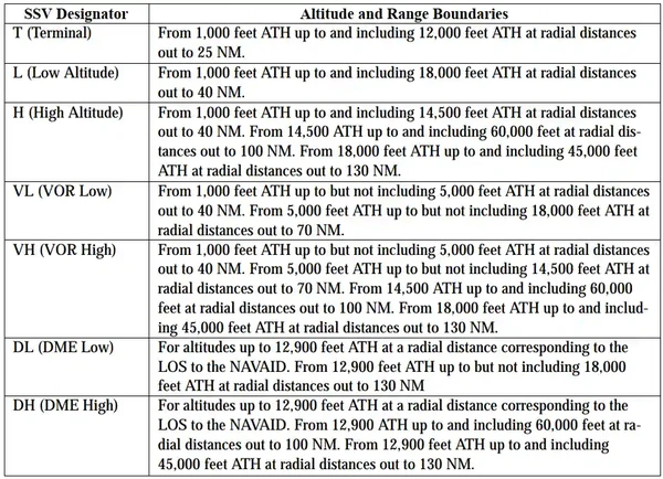
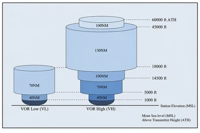
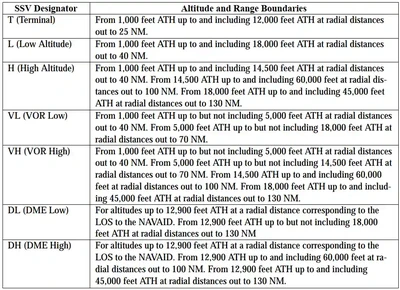
- Note the range of Jet Routes may be limited due to Standard Service Volume (SSV) of ground stations. [/]
- Jet routes have no defined width.
- A Navigational Aid (NAVAID) on a continuing jet route is NOT part of the segment and should not be included in your flight plan.

North American Route Program
- The latest version of Advisory Circular 90-91, North American Route Program (NRP), provides guidance to users of the National Airspace System (NAS) for participation in the NRP. []
- All flights operating at or above FL 290 within the conterminous United States and Canada are eligible to participate in the NRP, the primary purpose of which is to allow operators to plan minimum time/cost routes that may be off the prescribed route structure
- NRP aircraft are not subject to route-limiting restrictions (e.g., published preferred IFR routes) beyond a 200 NM radius of their point of departure or destination
Radar Vectors
- Controllers may vector aircraft within controlled airspace for separation purposes, noise abatement considerations, when an operational advantage will be realized by the pilot or the controller, or when requested by the pilot. Vectors outside of controlled airspace will be provided only on pilot request. Pilots will be advised as to what the vector is to achieve when the vector is controller initiated and will take the aircraft off a previously assigned nonradar route. To the extent possible, aircraft operating on RNAV routes will be allowed to remain on their own navigation
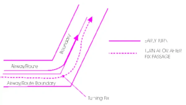
Turns
- Some variables which must be considered are turn radius, wind effect, airspeed, degree of turn, and cockpit instrumentation An early turn, as illustrated below, is one method of adhering to airways or routes. The use of any available cockpit instrumentation, such as Distance Measuring Equipment, may be used by the pilot to lead the turn when making course changes. This is consistent with the intent of 14 CFR Section 91.181, which requires pilots to operate along the centerline of an airway and along the direct course between navigational aids or fixes
- Turns which begin at or after fix passage may exceed airway or route boundaries. []
- Without such actions as leading a turn, aircraft operating in excess of 290 knots true air speed (TAS) can exceed the normal airway or route boundaries depending on the amount of course change required, wind direction and velocity, the character of the turn fix (DME, overhead navigation aid, or intersection), and the pilot's technique in making a course change. For example, a flight operating at 17,000 feet MSL with a TAS of 400 knots, a 25 degree bank, and a course change of more than 40 degrees would exceed the width of the airway or route; i.e., 4 nautical miles each side of centerline. However, in the airspace below 18,000 feet MSL, operations in excess of 290 knots TAS are not prevalent and the provision of additional IFR separation in all course change situations for the occasional aircraft making a turn in excess of 290 knots TAS creates an unacceptable waste of airspace and imposes a penalty upon the preponderance of traffic which operate at low speeds. Consequently, the FAA expects pilots to lead turns and take other actions they consider necessary during course changes to adhere as closely as possible to the airways or route being flown
- Turns that begin at or after fix passage may exceed airway or route boundaries
- Without such actions as leading a turn, aircraft operating in excess of 290 knots true airspeed (TAS) can exceed the normal airway or route boundaries depending on the amount of course change required, wind direction and velocity, the character of the turn fix (DME, overhead navigation aid, or intersection), and the pilot's technique in making a course changeover
Minimum Turning Altitude:
- Due to increased airspeeds at 10,000 ft MSL or above, the published minimum enroute altitude (MEA) may not be sufficient for obstacle clearance when a turn is required over a fix, NAVAID, or waypoint.
- In these instances, an expanded area in the vicinity of the turn point is examined to determine whether the published MEA is sufficient for obstacle clearance.
- In some locations (normally mountainous), terrain/obstacles in the expanded search area may necessitate a higher minimum altitude while conducting the turning maneuver.
- Turning fixes requiring a higher minimum turning altitude (MTA) will be denoted on government charts by the minimum crossing altitude (MCA) icon ("x" flag) and an accompanying note describing the MTA restriction.
- An MTA restriction will normally consist of the air traffic service (ATS) route leading to the turn point, the ATS route leading from the turn point, and the required altitude; e.g., MTA V330 E TO V520 W 16000.
- When an MTA is applicable for the intended route of flight, pilots must ensure they are at or above the charted MTA not later than the turn point and maintain at or above the MTA until joining the centerline of the ATS route following the turn point.
- Once established on the centerline following the turning fix, the MEA/MOCA determines the minimum altitude available for assignment.
- Note that while conventionally equipped aircraft must fly MEA, allowances for upgraded avionics, most notably GNSS equipped aircraft, allow for assignment down to MOCA.
- An MTA may also preclude the use of a specific altitude or a range of altitudes during a turn.
- For example, the MTA may restrict the use of 10,000 through 11,000 ft MSL.
- In this case, any altitude greater than 11,000 ft MSL is unrestricted, as are altitudes less than 10,000 ft MSL provided MEA/MOCA requirements are satisfied.
- NOTE:
When not along an airway, consider 91.177(a) for minimum altitudes
Preferred IFR Routes
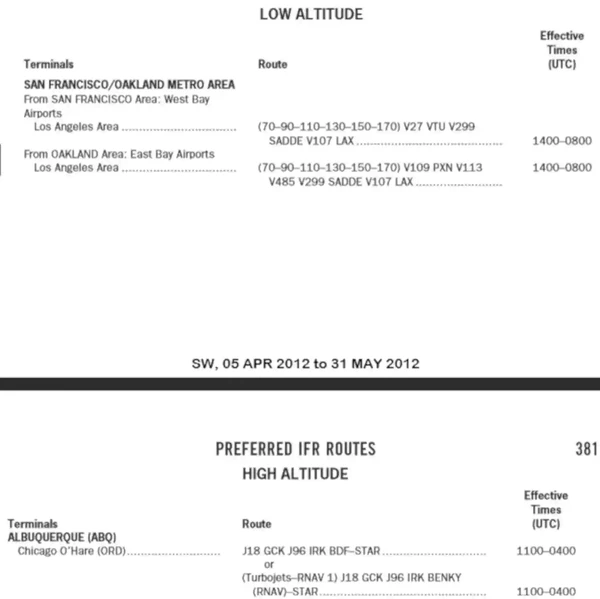
- Preferred IFR routes have been established between major terminals to guide pilots in planning their routes of flight, minimizing route changes, and aiding in the orderly management of air traffic on Federal airways
- Preferred IFR routes exists for the low altitude stratum and the high altitude stratum and are listed in the Chart Supplement U.S. Supplement
- The high altitude list is in two sections; the first section showing terminal to terminal routes and the second section showing single direction route segments
- Also, on some high altitude routes low altitude airways are included as transition routes
- To use a preferred route, reference the departure and arrival airports; if a routing exists for your flight, then airway instructions are listed. []
- Terms/abbreviations used in the listing:
- Preferred routes beginning/ending with an airway number indicate that the airway essentially overlies the airport and flight are normally cleared directly on the airway
- Preferred IFR routes beginning/ending with a fix indicate that aircraft may be routed to/from these fixes via a Standard Instrument Departure (SID) route, radar vectors (RV), or a Standard Terminal Arrival (STAR).
- Preferred IFR routes for major terminals selected are listed alphabetically under the name of the departure airport
- Where several airports are in proximity they are listed under the principal airport and categorized as a metropolitan area
- Example: New York Metro Area
- Preferred IFR routes used in one direction only for selected segments, irrespective of point of departure or destination, are listed numerically showing the segment fixes and the direction and times effective
- Where more than one route is listed the routes have equal priority for use
- Official location identifiers are used in the route description for VOR/VORTAC NAVAIDs
- Intersection names are spelled out
- NAVAID and distance fixes (e.g., ARD201113) have been used in the route description in an expediency and intersection names will be assigned as soon as routine processing can be accomplished. NAVAID radial (no distance stated) may be used to describe a route to intercept a specified airway (e.g., MIV MIV101 V39); another NAVAID radial (e.g., UIM UIM255 GSW081); or an intersection (e.g., GSW081 FITCH)
- Where two NAVAIDS, an intersection and a NAVAID, a NAVAID and a NAVAID radial and distance point, or any navigable combination of these route descriptions follow in succession, the route is direct
- The effective times for the routes are in UTC. During periods of daylight saving time effective times will be one hour earlier than indicated. All states observe daylight saving time except Arizona, Puerto Rico and the Virgin Islands. Pilots planning flight between the terminals or route segments listed should file for the appropriate preferred IFR route
- (90–170 incl) altitude flight level assignment in hundred of feet
- The notations "pressurized" and "unpressurized" for certain low altitude preferred routes to Kennedy Airport indicate the preferred route based on aircraft performance
- High Altitude Preferred IFR Routes are in effect during the following time periods unless otherwise noted
- Monday thru Friday: 0701–2259 local time
- Saturday: 0701–1459 local time
- Sunday: 1300–2259 local time
- Use current SIDs and STARSs for flight planning
- For high altitude routes, the portion of the routes contained in brackets [ ] is suggested but optional. The portion of the route outside the brackets will likely be required by the facilities involved. Separated into low and high altitude
- Tools such as ForeFlight and FltPlan.com also assist pilots in determining what flight plan is likely to be assigned based on clearances previously issued by Air Traffic Control
- When all else fails, pilots can always leverage the knowledge at their local airport.

Position Reports
- Reporting points are designated for VOR Airway/Jet Route Systems
- Flights using Victor Airways/Jet Routes will report over these points unless advised otherwise by ATC
Climbs
- Airways are designed for aircraft to begin climbing immediately after passing a point where a minimum enroute altitude increases
- Obstacle clearance is ensured if climb at 150 ft/min (to 5,000' AGL), 120 ft/nm (5,000'-10,000' AGL), and 100 ft/nm (>10,000' AGL)
- Example: you must begin your climb no later than COFFE if flying east on V244. []
- ATC will inform you prior to crossing the fix at which the minimum altitude changes but failing that, request it
- Note that minimum crossing altitudes require you to cross at or above the next segment minimum altitude.


Changeover Points (COP)
- COPs are prescribed for Federal airways, jet routes, area navigation routes, or other direct routes for which an MEA is designated under 14 CFR Part 95.
- The COP is a point along the route or airway segment between two adjacent navigation facilities or waypoints where changeover in navigation guidance should occur.
- At this point, the pilot should change navigation receiver frequency from the station behind the aircraft to the station ahead.
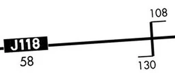
- The COP is normally located midway between the navigation facilities for straight route segments, or at the intersection of radials or courses forming a dogleg in the case of dogleg route segments.
- When the COP is NOT located at the midway point, aeronautical charts will depict the COP location and give the mileage to the radio aids. []
- Example: in the referenced figure, if flying from the left to right, you switch from the NAVAID behind you at 130 NM from, and 108 NM to the next, as the airway is defined
- When the COP is NOT located at the midway point, aeronautical charts will depict the COP location and give the mileage to the radio aids. []
- COPs are established for the purpose of preventing loss of navigation guidance, to prevent frequency interference from other facilities, and to prevent use of different facilities by different aircraft in the same airspace.
- Pilots are urged to observe COPs to the fullest extent.

Course Lights
- The course light, which can be seen clearly from only one direction, is used only with rotating beacons of the Federal Airway System:
- Two course lights, back to back, direct coded flashing beams of light in either direction along the course of airway
Aeronautical Light Beacons
- An aeronautical light beacon is a visual Navigational Aid (NAVAID) displaying flashes of white and/or colored light to indicate the location of an airport, a heliport, a landmark, a certain point of a Federal airway in mountainous terrain, or an obstruction.
- The light used may be a rotating beacon or one or more flashing lights.
- The flashing lights may be supplemented by steady burning lights of lesser intensity.
- The color or color combination displayed by a particular beacon and/or its auxiliary lights tell whether the beacon is indicating a landing place, landmark, point of the Federal airways, or an obstruction.
- Coded flashes of the auxiliary lights, if employed, further identify the beacon site.
-
Code Beacons:
- Code Beacons are omni-directional lights used to identify airports and landmarks.
- In the case of airports, they flash the 3 or 4 character airport identifier in Morse code 6 to 8 times a minute.
- Green flashes for land airports.
- Yellow for water airports.
-
Course Lights:
- Course lights, which can be seen clearly from only one direction, is used only with rotating beacons of the Federal Airway System: two-course lights, back to back, direct coded flashing beams of light in either direction along the course of airway.
- Airway beacons are remnants of the "lighted" airways which antedated the present electronically equipped federal airways system.
- Only a few of these beacons exist today to mark airway segments in remote mountain areas.
- Flashes in Morse code identify the beacon site.
Obstruction Lights
- Obstructions are marked and lit to warn airmen of their presence during daytime and night-time conditions
Aviation Red Obstruction Lights:
- During daylight hours, aviation orange and white paint is used for marking.
- During nighttime operation, a flashing red light bacon indicates the marking of an en-route obstruction (20 to 40 flashes per minute).
- Steady red light indicates an obstruction in the terminal area
Medium Intensity Flashing White Obstruction Lights:
- Medium intensity flashing white obstruction lights may be used during daytime and twilight with automatically selected reduced intensity for night-time operation.
- When this system is used on structures 500 feet (153m) AGL or less in height, other methods of marking and lighting the structure may be omitted.
- Aviation orange and white paint is always required for day time marking on structures exceeding 500' AGL.
- Not normally installed on structures less than 200' AGL.
High Intensity White Obstruction Light:
- Flashing high intensity white lights during daytime with reduced intensity for twilight and night-time operation.
- When this type of system is used, the marking of structures with red obstruction lights and aviation orange and white paint may be omitted.
- Dual Lighting:
- A combination of flashing aviation red beacons and steady burning aviation red lights for night time operation, and flashing high intensity white lights for daytime operation.
- Aviation orange and white paint may be omitted.
-
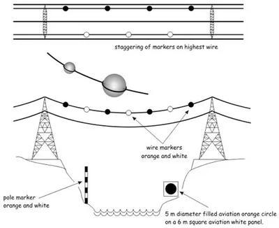
Catenary Lighting:
- Lighted markers are available for increased night conspicuity of high-voltage transmission line catenary wires.
- Lighted markers provide conspicuity both day and night.
- Medium intensity omni-directional flashing white lighting system provides conspicuity both day and night on catenary support structures.
- The unique sequential/simultaneous flashing light system alerts pilots of the associated catenary wires.
- High intensity flashing white lights are being used to identify some supporting structures of overhead transmission lines located across rivers, chasms, gorges, etc.
- These lights flash in a middle, top, lower light sequence at approximately 60 flashes per minute.
- The top light is normally installed near the top of the supporting structure, while the lower light indicates the approximate lower portion of the wire span.
- The lights are beamed toward the companion structure and identify the area of the wire span.
- High intensity flashing white lights are also employed to identify tall structures, such as chimneys and towers, as obstructions to air navigation.
- The lights provide a 360° coverage about the structure at 40 flashes per minute and consist of from one to seven levels of lights depending upon the height of the structure.
- Where more than one level is used the vertical banks flash simultaneously.

Deviations From Course
- Deviations may be authorized when necessary to avoid flying into something, usually weather
- "Request 10 degrees left for weather"
Airways & Route Course Change Knowledge Check


Airways & Route Course Change Conclusion
- Pilots of aircraft are required to adhere to airways or routes being flown
- Special attention must be given to this requirement during course changes.
- If you get a lock on the next NAVAID along your route, you can always ask for direct to save time/gas
- Each course change consists of variables that make the technique applicable in each case a matter only the pilot can resolve.
- Some variables which must be considered are turn radius, wind effect, airspeed, degree of turn, and cockpit instrumentation.
- An early turn is one method of adhering to airways or routes.
- Additional tools are available to find preferred routes, including ForeFlight and FlightPlan.com
- Make sure the routes presented can be flown before filing!
- The use of any available cockpit instrumentation, such as DME, may be used by the pilot to lead the turn when making course changes
- This consistent with the intent of 91.181 which requires pilots to operate along the center line of an airway and along the direct course between navigational aids or fixes
- Do not file through any special use airspace.
- When flying in Canadian airspace, pilots are cautioned to review Canadian Air Regulations
- Still looking for something? Continue searching:
Airways & Route Course Change References
- Federal Aviation Administration - Pilot/Controller Glossary.
- Aeronautical Information Manual (2-2-1) Aeronautical Light Beacons.
- Aeronautical Information Manual (2-2-2) Code Beacons and Course Lights.
- Aeronautical Information Manual (2-2-3) Obstruction Lighting.
- Aeronautical Information Manual (5-3-5) Airway or Route Course Changes.
- Aeronautical Information Manual (5-3-6) Changeover Points (COPs).
- Aeronautical Information Manual (5-3-7) Minimum Turning Altitude (MTA).
- FAA - JO 7110.65.
- Federal Aviation Regulations (91.177) Minimum altitudes for IFR operations.
- Federal Aviation Regulations (91.181) Course to be flown.
- Instrument Flying Handbook (1-5) Other Routing.
- Instrument Procedures Handbook (Appendix C) Navigational Gap.
- Pilot Workshops - Preferred IFR Routes.