Aircraft Holding Procedures
Holding keeps an aircraft within specific airspace while awaiting further clearance from ATC or when a loss of altitude is required.
Introduction to Aircraft Holding Procedures
- As the name suggests, holding is the act of delaying an aircraft from proceeding on course
- Holding becomes necessary when there is a need to keep air traffic within specified airspace that is reasonably protected
- Different types of holding patterns are established based on their purpose and phase of flight
- Holding consists of several holding orbits, which the pilot must maintain
- Air Traffic Control (ATC) issues holding clearances
- Holding can be accomplished at a Navigational Aid (NAVAID), a fix, or an intersection, dictating how pilots execute their holding procedures
- Practice holding procedures is critical as this can be a perishable skill
- While holding is an IFR task, under certain circumstances, VFR operations require holding
WARNING:
All procedures are GENERALIZED.
Use the Pilot Operating Handbook (POH) procedures for specific aircraft performance and limitations.
and/or current Standard Operating Procedures (SOPs).
Aircraft Holding Procedures Key Highlights
- Aircraft holding procedures are used to delay aircraft within protected airspace while maintaining safe separation and organized traffic flow.
- Holding patterns typically consist of racetrack-shaped courses flown around a designated fix using inbound and outbound legs.
- Standard holding patterns use right turns unless otherwise published or assigned by air traffic control.
- Pilots must determine the appropriate holding entry procedure, such as direct, parallel, or teardrop entry.
- Wind correction techniques are essential to maintain accurate holding pattern timing and course tracking.
- Holding clearances normally include the holding fix, direction, radial or course, leg length, turn direction, and expected further clearance time.
- Pilots should monitor fuel status, aircraft performance, and situational awareness carefully during extended holding operations.
- Instrument holding procedures require precise navigation, timing, and workload management skills.
- Modern GPS and flight management systems can assist with holding pattern navigation and situational awareness.
- Understanding aircraft holding procedures improves instrument proficiency, traffic management awareness, and overall flight safety.
Aircraft Holding Purpose
- Aircraft may be required to hold for a variety of reasons, including:
- Traffic congestion,
- Aircraft emergency,
- Equipment outage,
- Waiting for an Expect Further Clearance time,
- Pilots require time to make a decision,
- Poor weather, or
- Unavailability of the runway
Types of Holding Patterns
-
Instrument Approach Procedures
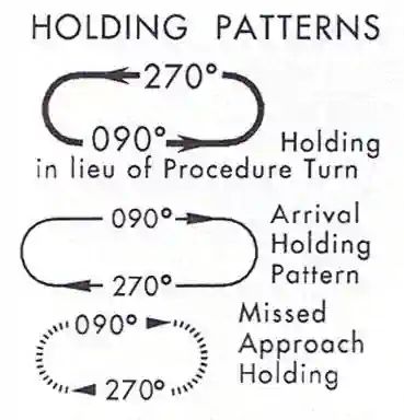
Holding Pattern Legend - There are three types of holding, all of which instrument approach chart legends depict: [Figure 1]
-
Holding in Lieu of a procedure turn:
-
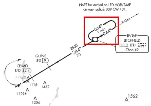
Holding in Lieu of a Procedure Turn Example - Depicted as a solid bold line on an instrument approach [Figure 2]
- In practice, holding in lieu is not really a holding pattern, but a method by which to turn around (course reversal)
- When used, you do not need to go outbound for the full distance but rather after 1 minute you should turn back in and execute the approach
-
-
Arrival Pattern:
- Arrival patterns are used to control the flow of traffic on an approach
- Depicted as a thin solid line on instrument charts
- Think of it as adding a delay to ensure the airport environment is clear
- The arrival holding pattern is not authorized unless assigned by ATC
-
Missed Approach:
- Visually depicts holding following the execution of a missed approach
- Depicted as a dashed line on instrument approach procedure
- This pattern is considered the "published missed"
- Many times ATC will assign alternate instructions to facilitate traffic flow, especially during practice approaches
-
Holding Pattern Airspace Protection
- Holding areas must be designated as protected, i.e., free from obstacles
- Holding pattern airspace protection is therefore provided by controlling the pattern's location and size
-
Holding Pattern Direction/Layout:
- The FAA's standard pattern consists of right turns (think that most are right-handed, making that standard)
- Although non-standard, left turns may be assigned
- Holding patterns depicted in the instrument approach plate legend show both left and right turns and are in no way an indication of standards
- The FAA's standard pattern consists of right turns (think that most are right-handed, making that standard)
-
Holding Pattern Altitude:
- Logically, obstacle protection increases with altitude
- More importantly, altitude impacts airspeeds due to the operation (aircraft operating at higher altitudes fly faster)
- The standard altitude blocks that we are concerned with are:
- Surface to 6000 feet MSL
- 6001 feet to 14,000 feet MSL
- and 14,001 feet MSL and higher
- These altitude blocks correspond to maximum airspeeds
-
Holding Pattern Airspeeds:
- Holding is generally performed at max endurance to conserve fuel
- Holding patterns may be restricted to a maximum speed
- ATC: "[Callsign] [holding instructions], maximum holding speed is [Speed in Knots]"
- Holding speeds are based on an expected turn radius to keep pilots clear of obstacles
- Charts depict speed restriction in parenthesis inside the holding pattern on the chart: e.g., (175)
- Pilots unable to comply with the maximum airspeed restriction should notify ATC
- The aircraft should be at or below the maximum speed before initially crossing the holding fix to avoid exiting the protected airspace
Below 6,000' MSL:
200 Knots Indicated Airspeed (KIAS)6001' MSL to 14,000' MSL:
230 KIAS- Holding patterns from 6,001' to 14,000' may be further restricted to 210 KIAS
14,001' MSL and up:
265 KIAS- Note that holding speeds change at 14,001 (as does the holding time (1.0 to 1.5 minutes))
U.S. Air Force Airfields:
310 KIASU.S. Navy Airfields:
230 KIAS
- All helicopter/power lift aircraft holding on a "COPTER" instrument procedure is predicated on a minimum airspeed of 90 KIAS unless charted otherwise
- When a published procedure directs a climb-in hold (i.e., "Climb-in holding pattern to depart XYZ VORTAC at or above 10,000" or "All aircraft climb-in TRUCK holding pattern to cross TRUCK Int at or above 11,500 before proceeding on course"), an additional obstacle protection area allows for greater airspeeds in the climb for those aircraft requiring them
- Climb-in-holding permits a maximum airspeed of 310 KIAS unless a maximum holding airspeed is published, in which case that maximum airspeed is applicable
- Where the holding pattern is restricted to a maximum airspeed of 175 KIAS, the 200 KIAS holding pattern template has been applied for published climb-in hold procedures for altitudes 6,000 feet and below and the 230 KIAS holding pattern template has been applied for altitudes above 6,000 feet
- The airspeed limitations in 14 CFR Section 91.117, Aircraft Speed, still apply
- The following phraseology may be used by an ATC to advise a pilot of the maximum holding airspeed for a holding pattern airspace area:
- "[Callsign], [Holding instructions, when needed], maximum holding airspeed is [Speed in knots]"
-
Holding Pattern Timing:
- Some aircraft will have timers, but you can also bring a stand-alone Flight Timer/watch [Amazon] to mount to the aircraft or kneeboard
-
Inbound Leg Timing:
- At or below 14,000' MSL, legs are timed to equal 1 minute
- Above 14,000' MSL, legs are timed to equal 1 and 1/2 minutes
- To remember this rule, remember that no one will make you hold at 14,001' but rather 14,000 or 15,000, most likely. The 1.5-minute leg comes to play at 15k 10% RULE: 15 = 1.5 minutes
- Timing inbound is measured from the point that the aircraft is wings level, inbound to the holding fix, to the time the aircraft crosses the holding fix
-
Outbound Leg Timing:
- Outbound time is adjusted to achieve the correct inbound timing
- Outbound leg timing begins over/abeam the fix, whichever occurs later
- If the abeam position cannot be determined, start timing when the turn outbound is completed
- Abeam is when the needle drops below the 90° benchmark in the HSI, not the TO/FROM flip
- The initial outbound leg should be flown for 1 minute or 1 1/2 minutes (appropriate to altitude)
- Pilots may use any navigational means available; i.e., DME, RNAV, etc., to ensure the appropriate inbound leg times
- Timing is generally associated with VOR holding, but some TACAN holds may require timing if no specified DME in the holding clearance
-
- Holding protected airspace is designed based in part on pilot compliance with the three recommended holding pattern entry procedures
- Deviations from these recommendations, coupled with excessive airspeed crossing the holding fix, may in some cases result in the aircraft exceeding holding protected airspace
Holding Orbits
-

Holding Pattern Entry Procedures - Holding consists of several orbits in an oval-shaped pattern
- The first orbit is the entry orbit, which expeditiously establishes the aircraft inbound on the holding courses
- The second orbit is the no-wind orbit, which sets the baseline from which all corrections will be made
- The last orbit flown is the correction orbit, which updates and refines the wind corrections
-
Entry Orbit:
- The entry orbit establishes the aircraft into the holding pattern
- There are three types: the direct, parallel, and teardrop entry
-
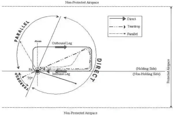
Direct Entry:
- When approaching the holding fix from anywhere in sector (c), the direct entry procedure would be to fly directly to the fix and turn to follow the holding pattern [Figure 3]
-
Parallel Entry:
- When approaching the holding fix from anywhere in sector (a), the parallel entry procedure would be to turn to a heading to parallel the holding course outbound on the non-holding side for one minute, turn in the direction of the holding pattern through more than 180 degrees, and return to the holding fix or intercept the holding course inbound [Figure 3]
- Right turns: first turn left, then left, and finally right
- Left turns: first turn right, then right, and finally left
- When approaching the holding fix from anywhere in sector (a), the parallel entry procedure would be to turn to a heading to parallel the holding course outbound on the non-holding side for one minute, turn in the direction of the holding pattern through more than 180 degrees, and return to the holding fix or intercept the holding course inbound [Figure 3]
-
Teardrop Entry:
- When approaching the holding fix from anywhere in sector (b), the teardrop entry procedure would be to fly to the fix, turn outbound to a heading for a 30-degree teardrop entry within the pattern (on the holding side) for one minute, then turn in the direction of the holding pattern to intercept the inbound holding course [Figure 3]
- Remember Left Add Right Subtract, or LARS for short
- L+30
- R-30
- Remember Left Add Right Subtract, or LARS for short
- When approaching the holding fix from anywhere in sector (b), the teardrop entry procedure would be to fly to the fix, turn outbound to a heading for a 30-degree teardrop entry within the pattern (on the holding side) for one minute, then turn in the direction of the holding pattern to intercept the inbound holding course [Figure 3]
- While other entry procedures may enable the aircraft to enter the holding pattern and remain within protected airspace, the parallel, teardrop, and direct entries are the procedures for entry and holding recommended by the FAA, derived as part of the development of the size and shape of the obstacle protection areas for holding
-
No-wind Orbit:
- The no wind orbit begins the second time the aircraft crosses the station or fix, allowing the pilot to determine the initial corrections required for existing winds
- As the name suggests, this orbit is flown as if there were no-wind for which to compensate
- If this were true, you would (1) roll out of your inbound turn on the holding course and (2) inbound timing to the holding fix, if required, would equal the amount of time outbound
- Pilots must execute the no-wind orbit as precisely as possible to identify initial corrections
-
Correction Orbit(s):
- The third and subsequent orbits in holding are called correction orbits
- Correction orbits apply the correction factors determined on the previous orbit to the outbound leg of the holding pattern
- Adjust the heading by the correction factor determined on the no-wind orbit
- TAIL-RADIAL-WIND
- Confirm EFC 5 minutes before it is reached
- Be as exact on corrections as possible
- Compensate for wind effect primarily by drift correction on the inbound and outbound legs
- When outbound, triple the inbound drift correction to avoid major turning adjustments; e.g., if correcting left by 8 degrees when inbound, correct right by 24 degrees when outbound
-
VOR Correction Factor:
- Apply full correction outbound (if off 10°, apply 10°)
- Apply 1/3 of the wind correction inbound
-
TACAN (DME) Correction Factor:
- Use full correction into the wind on the outbound leg
- Use half correction into the wind on the inbound leg
- DME of longest leg X degrees off = correction factor you will use
-
Holding Entries Overview
Holding Clearance
- Air Traffic Control clearances will come with a clearance limit, be in the airport (no delay expected), or a NAVAID (delay expected)
- When no delay is expected, the controller should issue a clearance beyond the fix as soon as possible and, whenever possible, at least 5 minutes before the aircraft reaches a clearance limit
- If unable to issue a clearance to the destination, an ATC clearance requiring an aircraft to hold at a fix where the no pattern is charted will include the following information:
- The direction of holding from the fix in terms of the eight cardinal compass points (i.e., N, NE, E, SE, etc.)
- The name of the holding fix
- Omitted if included at the beginning of the transmission as the clearance limit
- The radial, course, bearing, airway, or route on which the aircraft is to hold
- The leg length in miles if using DME or RNAV
- Specified in minutes on pilot request or if the controller considers it necessary
- The direction of turn if left turns are required, the pilot requests, or the controller considers it necessary
- Time to expect further clearance (EFC) and any pertinent additional delay information (times are in Zulu)
- ATC: "Hold east of the Ormond VORTAC on the 090 radial, left turns, maintain 5,000,' expect further clearance 0+50"
- At a minimum, the only information you need is the location, the radial, and the EFC time
- When charted, the controller may omit all holding instructions, except the charted holding direction and the statement "as published"
- ATC: "Hold east as published"
- Controllers shall always issue complete holding instructions when pilots request them
- Request EFC time if not automatically provided by ATC
Aircraft Holding Procedures
WARNING:
All procedures are GENERALIZED.
Use the Pilot Operating Handbook (POH) procedures for specific aircraft performance and limitations.
and/or current Standard Operating Procedures (SOPs).- Copy and read back holding clearance
- Format: [direction to hold from the holding fix], [name of holding fix], [radial, course, bearing, airway, or route on which the aircraft is to hold], [leg length in miles if using DME or RNAV], [direction of turn if left turns are required], [time to expect further clearance (EFC)]"
- ATC: "Hold east of the Ormond VORTAC on the 090 radial, left turns, maintain 5,000,' expect further clearance 0+50"
- Verify that the Heading Indicator or Horizontal Situational Indicator is aligned with the magnetic compass
- Tune and identify the appropriate NAVAID(s)
- Proceed directly to the holding fix
- Determine the holding course and reciprocal of the holding course (radial)
- The holding course is the inbound course to the holding fix
- The reciprocal of the holding course (radial) determines the direction of entry turn. When the holding fix is a NAVAID, the reciprocal will be the same as the radial
- Determine the aircraft position relative to the holding fix and determine the type of entry orbit (described above) to use
- To determine the type of entry, pilots can utilize many different methods:
-
Pencil Method:
- If instructed to perform left turns:
- Raise the left side of the pencil 20° and see where the reciprocal course lies
- If instructed to perform right turns:
- Raise the right side of the pencil 20° and see where the reciprocal course lies
- If instructed to perform left turns:
-
Sector Method:
- There will be cases in which the reciprocal will fall on, or very close to (±5°) a sector boundary in which case the entry procedures for either section are acceptable
-
- To determine the type of entry, pilots can utilize many different methods:
- Start speed reduction when 3 minutes or less from the holding fix
- When an aircraft is 3 minutes or less from a clearance limit and a clearance beyond the fix has not been received, the pilot is expected to start a speed reduction so that the aircraft will cross the fix, initially, at or below the maximum holding airspeed
- If appropriate, suspend the GPS
- Perform the entry orbit
- Crossing the holding fix, perform the "5 Ts"
- TIME: note the time of entry; start timing the legs when wings level or abeam the station (head of the needle on or below the 90), whichever occurs last
- TURN: turn as determined to execute entry with whichever of the below requires the least bank angle:
- Perform all turns at 3 per second; or 30° angle of bank; or 25° angle of bank if using a flight director system, whichever requires the least bank angle
- TWIST/TYPE: verify that the OBS is set to the inbound course/put the holding course into the HI/HSI
- THROTTLE: Maintain holding speed
- TALK: give the voice report and check EFC
- Pilot: "[Place], [Callsign], holding at [Location], [Time], [Altitude]"
- After completion of outbound timing (according to altitude) or at the specified DME, turn (standard rate) to intercept the holding course inbound
- During the last half of the turn, check the position of the head of the needle relative to the holding course
- The head of the needle should always be in a place to fall onto the course when you're checking your turn inbound
- If not on course, stop the turn with a double the angle intercept for VOR holding
- When turning to intercept the inbound course in TACAN holding, an intercept greater than double the angle will be required
- Begin timing once wings level inbound to the fix or station
- This is to compensate for greater spacing between radials when holding away from the station
- In TACAN holding, a 30 to 45° angle of intercept will establish the aircraft on the inbound course
- Once established on course, commence tracking inbound to the holding fix
- It is critical to establish the aircraft on course before crossing the holding fix
- Continue to the station and initiate your turn in the direction of holding to begin the no wind orbit
- Roll out of the turn on the outbound heading parallel to the holding course
- Start the outbound leg timing, if required, when wings are level or abeam the station, whichever occurs later
- If the abeam position cannot be determined, start timing when the turn to the outbound leg has been completed
- When holding at a VOR station, pilots should begin the turn to the outbound leg at the time of the first complete reversal of the to/from indicator
- At the completion of the outbound leg timing or at the specified DME, turn toward the holding radial to intercept the holding course
- As you roll wings level, check the position of the head of the needle to the holding course
- If they differ, note the number of degrees difference
- This will determine the amount of heading correction to use on the outbound leg of your correction orbit
- Do this as quickly as possible
- If they differ, note the number of degrees difference
- If you had to set an intercept when you turned inbound, there are winds to correct for
- TAIL - RADIAL - WIND
- When checking the wind, resist the temptation to check wind from the head of the needle because it will be on the top of the RMI where you are looking; this will give you opposite winds causing an error
- Establish the aircraft on the holding course and track inbound to the holding fix
- Start inbound time at wings-level on the inbound course or on a heading to intercept the inbound course, whichever occurs first. note the heading that maintains the course inbound
- At station passage, note how much time has elapsed on the inbound leg
- Determine the difference between the elapsed time and the desired inbound timing
- You will use this correction factor for timing on the outbound leg of your correction orbit
- AFTER EVERY ORBIT, DO THE Ts. IF A STEP DOES NOT APPLY, IGNORE IT, BUT TIME IS ALWAYS AN EFC CHECK TO GET AN UPDATE WITHIN 5 MINUTES OF THE REPORTED EFC TIME
- Adjust the outbound leg time to achieve a one-minute inbound leg time
- Pilots should report to ATC the time and altitude/flight level at which the aircraft reaches the clearance limit and report leaving the clearance limit
- In the event of two-way communications failure, pilots are required to comply with 14 CFR Section 91.185
- Patterns at the most generally used holding fixes are depicted (charted) on U.S. Government or commercially produced (meeting FAA requirements) Low or High Altitude En Route, Area, Departure Procedure, and STAR Charts
- Pilots are expected to hold in the pattern depicted unless specifically advised otherwise by ATC
- Holding patterns that protect for a maximum holding airspeed other than the standard may be depicted by an icon, unless otherwise depicted
- The icon is a standard holding pattern symbol (racetrack) with the airspeed restriction shown in the center
- In other cases, the airspeed restriction will be depicted next to the standard holding pattern symbol
- UHF: "[Place], [Callsign], departing holding"
-
Departing From a Holding Pattern:
- When holding at a fix and instructions are received specifying the time of departure from the fix, the pilot should adjust the aircraft's flight path within the limits of the established holding pattern to leave the fix at the exact time specified
- After departing the holding fix, normal speed is to be resumed with respect to other governing speed requirements, such as terminal area speed limits, specific ATC requests, etc.
- Where the fix is associated with an instrument approach and timed approaches are in effect, a procedure turn must not be executed unless the pilot advises ATC, since aircraft holding are expected to proceed inbound on final approach directly from the holding pattern when approach clearance is received
- Report to ATC when leaving the holding fix
- Advise ATC immediately what increased airspeed is necessary, if any, due to turbulence, icing, etc., or if unable to accomplish any part of the holding procedures. When such higher speeds become no longer necessary, operate according to the appropriate published holding speed and notify ATC
Holding Considerations
Radar Surveillance of Outer Fix Holding Pattern Airspace Areas
- Whenever aircraft are holding at an outer fix, ATC will usually provide radar surveillance of the outer fix holding pattern airspace area, or any portion of it, if it is shown on the controller's radar scope
- The controller will attempt to detect any holding aircraft that stray outside the holding pattern airspace area and will assist any detected aircraft to return to the assigned airspace area
- Many factors could prevent ATC from providing this additional service, such as workload, number of targets, precipitation, ground clutter, and radar system capability. These circumstances may make it unfeasible to maintain radar identification of aircraft to detect aircraft straying from the holding pattern. The provision of this service depends entirely upon whether controllers believe they are in a position to provide it and does not relieve a pilot of their responsibility to adhere to an accepted ATC clearance
- If an aircraft is established in a published holding pattern at an assigned altitude above the published minimum holding altitude and subsequently cleared for the approach, the pilot may descend to the published minimum holding altitude. The holding pattern would only be a segment of the IAP if it is published on the instrument procedure chart and is used in lieu of a procedure turn
Intersection Holding Steps That Must Be Repeated
| Dual Nav | Single Nav | |
| Time | Yes | Yes |
| Tune | No | Yes |
| ID | No | Yes |
| Toggle | Yes | No |
| Twist | Yes | Yes |
Distance Measuring Equipment (DME)/GPS Along-Track Distance (ATD)
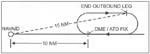
- DME/GPS holding is subject to the same entry and holding procedures except that distances (nautical miles) are used in lieu of time values
- The outbound course of the DME/GPS holding pattern is called the outbound leg of the pattern
- The controller or the instrument approach procedure chart will specify the length of the outbound leg
- The end of the outbound leg is determined by the DME or ATD readout
- The holding fix on conventional procedures, or controller defined holding based on a conventional navigation aid with DME, is a specified course or radial and distances are from the DME station for both the inbound and outbound ends of the holding pattern
- When flying published GPS overlay or stand alone procedures with distance specified, the holding fix will be a waypoint in the database and the end of the outbound leg will be determined by the ATD
- Some GPS overlay and early stand alone procedures may have timing specified
- See Global Positioning System (GPS) page, for requirements and restriction on using GPS for IFR operations
- When the inbound course is toward the NAVAID, the fix distance is 10 NM, and the leg length is 5 NM, then the end of the outbound leg will be reached when the DME/ATD reads 15 NM [Figure 3]
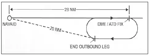
- When the inbound course is away from the NAVAID and the fix distance is 28 NM, and the leg length is 8 NM, then the end of the outbound leg will be reached when the DME/ATD reads 20 NM [Figure 4]
- The inbound course is always toward the waypoint and the ATD is zero at the waypoint. The end of the outbound leg of the holding pattern is reached when the ATD reads the specified distance [Figure 5]
-
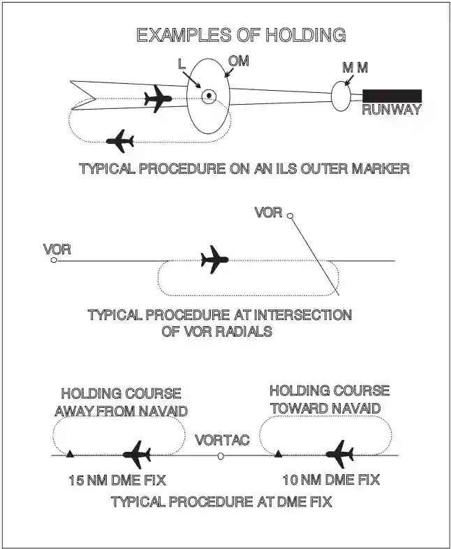
Examples of Holding -
Inbound Toward NAVAID -
Inbound Leg Away from NAVAID -
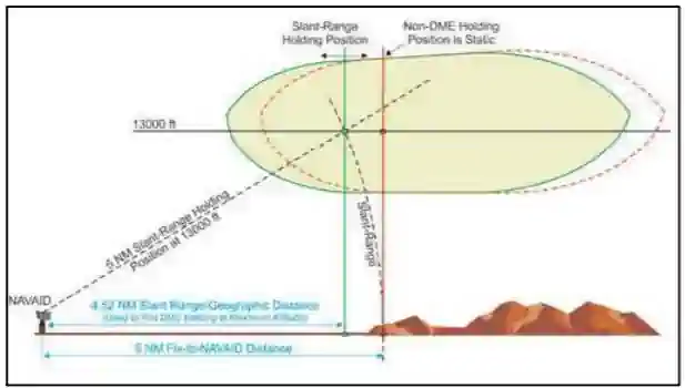
Difference Between DME Distance From NAVAID & RNAV Computed Distance From NAVAID
Practicing Holding
- Request a few turns in holding when you want practice
- If you request 1 turn in holding, your entry doesn't count
- In other words when you enter holding at first and initially pass the fix (even if a direct entry), then that orbit doesn't count
- 1 full round in the pattern is the 1 you requested
Reverse Sensing
- Reverse sensing is a conditions where the navigation instrument indicates the inverse of what it should
- To avoid reverse sensing:
- Intercept and track inbound TO
- Intercept and track outbound FROM
VFR Holding
- While rare, federal aviation regulation 91.159 (VFR cruising altitude) references VFR holding
- Usually it is just an ATC instruction to remain clear of a particular area or airspace, or to circle a known point
- Sometimes it is a little more in-depth and part of local traffic flow such as for an event; for example, Oshkosh
Holding Responsibilities
- Whenever an aircraft is cleared to a fix other than the destination airport and delay is expected, it is the responsibility of ATC to issue complete holding instructions (unless the pattern is charted), an EFC time and best estimate of any additional en route/terminal delay
- Only those holding patterns depicted on U.S. government or commercially produced (meeting FAA requirements) low/high altitude en route, and area or STAR charts should be used
- If the holding pattern is charted and the controller doesn't issue complete holding instructions, the pilot is expected to hold as depicted on the appropriate chart
- When the pattern is charted on the assigned procedure or route being flown, ATC may omit all holding instructions except the charted holding direction and the statement AS PUBLISHED; for example, HOLD EAST AS PUBLISHED
- ATC must always issue complete holding instructions when pilots request them
- If no holding pattern is charted and holding instructions have not been issued, the pilot should ask ATC for holding instructions prior to reaching the fix
- This procedure will eliminate the possibility of an aircraft entering a holding pattern other than that desired by ATC
- If unable to obtain holding instructions prior to reaching the fix (due to frequency congestion, stuck microphone, etc.), then enter a standard pattern on the course on which the aircraft approached the fix and request further clearance as soon as possible
- In this event, the altitude/flight level of the aircraft at the clearance limit will be protected so that separation will be provided as required
- Pilot Actions:
- Start speed reduction when 3 minutes or less from the holding fix. Cross the holding fix, initially, at or below the maximum holding airspeed
- Make all turns during entry and while holding at:
- 3 degrees per second; or
- 30 degree bank angle; or
- 25 degree bank provided a flight director system is used
- NOTE-Use whichever requires the least bank angle
- Compensate for wind effect primarily by drift correction on the inbound and outbound legs. When outbound, triple the inbound drift correction to avoid major turning adjustments; e.g., if correcting left by 8 degrees when inbound, correct right by 24 degrees when outbound
- Determine entry turn from aircraft heading upon arrival at the holding fix; +/-5 degrees in heading is considered to be within allowable good operating limits for determining entry
- Advise ATC immediately what increased airspeed is necessary, if any, due to turbulence, icing, etc., or if unable to accomplish any part of the holding procedures. When such higher speeds become no longer necessary, operate according to the appropriate published holding speed and notify ATC
Instrument Rating - Holding Procedures Airman Certification Standards
- Objective: To determine whether the applicant exhibits satisfactory knowledge, risk management, and skills associated with holding procedures solely by reference to instruments
- References: 14 CFR part 91; AIM; FAA-H-8083-2 (Risk Management Handbook), FAA-H-8083-3 (Airplane Flying Handbook), FAA-H-8083-15, FAA-H-8083-16, FAA-H-8083-25 (Pilot Handbook of Aeronautical Knowledge)
Instrument Rating - Holding Procedures Knowledge:
The applicant demonstrates an understanding of:Instrument Rating - Holding Procedures Risk Management:
The applicant is able to identify, assess, and mitigate risks associated with:-
IR.III.B.R1:
Recalculating fuel reserves if assigned an unanticipated expect further clearance (EFC) time -
IR.III.B.R2:
Scenarios and circumstances that could result in minimum fuel or the need to declare an emergency -
IR.III.B.R3:
Scenarios that could lead to holding, including deteriorating weather at the planned destination -
IR.III.B.R4:
Holding entry and wind correction while holding
Instrument Rating - Holding Procedures Skills:
The applicant exhibits the skills to:-
IR.III.B.S1:
Use an entry procedure appropriate for a standard, nonstandard, published, or non-published holding pattern -
IR.III.B.S2:
Change to the holding airspeed appropriate for the altitude when 3 minutes or less from, but prior to arriving at, the holding fix and set appropriate power as needed for fuel conservation -
IR.III.B.S3:
Recognize arrival at the holding fix and promptly initiate entry into the holding pattern-
IR.III.B.S3a:
Comply with the holding pattern leg length and other restrictions, if applicable, associated with the holding pattern
-
-
IR.III.B.S4:
Maintain airspeed ±10 knots, altitude ±100 feet, selected headings within ±10°, and track a selected course, radial, or bearing within ¾-scale deflection of the course deviation indicator (CDI) -
IR.III.B.S5:
Use proper wind correction procedures to maintain the desired pattern and to arrive over the fix as close as possible to a specified time -
IR.III.B.S7:
Comply with ATC reporting requirements and restrictions associated with the holding pattern -
IR.III.B.S8:
Use single-pilot resource management (SRM) or crew resource management (CRM), as appropriate
Aircraft Holding Procedures Conclusion
- Remain mindful that performance calculations are usually more optimistic than actual performance
- Holding is a solution to a temporary problem
- Do not hold for an approach you cannot legally execute!
- If current weather at destination is less than published weather minimums for any suitable approach, request clearance to your alternate airport, that is what it is there for
- The procedures above are recommended to ensure that the aircraft remains within holding protected airspace when holding is performed using either conventional NAVAID guidance or when using RNAV lateral guidance
- If cleared for the approach when in holding and flying outbound, you do not have to fly outbound any longer, turn in and shoot the approach
- Holding has a lot of variables which must be understood to be flown properly
- Remember, there may be aircraft stacked above or below you in holding
- It is therefore key that task saturation does not allow for altitude deviations while flying set airspeeds and controlling timing
- For those holding patterns where there are no published minimum holding altitudes, the pilot, upon receiving an approach clearance, must maintain the last assigned altitude until leaving the holding pattern and established on the inbound course. Thereafter, the published minimum altitude of the route segment being flown will apply. It is expected that the pilot will be assigned a holding altitude that will permit a normal descent on the inbound course
- Self test: https://www.lunabase.org/~faber/Vault/software/hold_quiz/
- Picturing holding patterns makes it a lot easier, draw if necessary
- If holding should not be accomplished (i.e., during an emergency), ask for radar vectors to achieve a similar end-state to holding
- Consider actual versus realized performance when doing any performance calculations
- Consider practicing maneuvers on a flight simulator to introduce yourself to maneuvers or knock off rust
- When asking yourself which direction for a holding pattern is standard think of the saying that: it is right to turn right (standard)
- CFI Notebook.net - Missed Approach
- Still looking for something? Continue searching:
Aircraft Holding Procedures References
- Aeronautical Information Manual (4-4-3) Clearance Items
- Aeronautical Information Manual (5-3-7) Minimum Turning Altitude (MTA)
- Aeronautical Information Manual (5-3-8) Holding
- Aeronautical Information Manual (5-4-9) Procedure Turn and Hold-in-lieu of Procedure Turn
- AOPA - IFR Fix: What Were They Thinking?
- Dauntless Soft.com
- Federal Aviation Administration - Airman Certification Standards
- Federal Aviation Administration - Pilot/Controller Glossary
- Instrument Flying Handbook