IFR En Route Charts
Instrument Flight Rules En-Route Charts establish navigation references for use during instrument flight rules operations.
Introduction to IFR En Route Charts
- The objective of IFR (Instrument Flight Rules) en route flight is to navigate within the lateral limits of a designated airway at an altitude consistent with the ATC (Air Traffic Control) clearance.
- Your ability to fly instruments safely and competently in the system is greatly enhanced by understanding the vast array of data available to the pilot on instrument charts.
- AeroNav Products maintains and produces the charts for the U.S. Government.
- En route high-altitude charts provide aeronautical information for en route instrument navigation at or above 18,000' MSL (Mean Sea Level).
- Information includes the portrayal of Jet and RNAV (Area Navigation) routes, identification and frequencies of radio aids, selected airports, distances, time zones, special use airspace, and related information.
- Established jet routes from 18,000' MSL to FL (Flight Level) 450 use NAVAIDs (Navigational Aids) not more than 260 nautical miles (NM) apart.
- The charts are revised every 56 days.
- To effectively depart from one airport and navigate en route under instrument conditions, a pilot needs the appropriate IFR en route low-altitude chart(s).
- The IFR low altitude en route chart is the instrument equivalent of the sectional chart.
- When folded, the cover of the AeroNav Products en route chart displays an index map of the United States showing the coverage areas.
- Cities near congested airspace are shown in black type and their associated area chart is listed in the box in the lower left-hand corner of the map coverage box.
- Also noted is an explanation of the off-route obstruction clearance altitude (OROCA).
- The effective date of a printed chart is printed on the other side of the folded chart. Compare that date with the current FAA chart cycle or product schedule to verify that the chart is current. For an electronic chart, verify the displayed chart edition and effective dates before use.
- Information concerning MTRs (Military Training Routes) is also included on the chart cover.
- The en route charts are revised every 56 days.
- When the AeroNav Products en route chart is unfolded, the legend is displayed and provides information concerning airports, NAVAIDs, communications, air traffic services, and airspace.
- Test your understanding of IFR En Route Charts by completing the knowledge quiz, applying your knowledge in the interactive scenario, comparing your performance against the applicable Airman Certification Standards, and concluding with the topic summary to reinforce the key concepts before moving on to the next lesson.
IFR En Route Charts Key Highlights
- IFR en route charts provide navigation, airway, altitude, and airspace information for instrument flight operations.
- Low-altitude and high-altitude IFR charts support aircraft navigation within the National Airspace System under instrument flight rules.
- IFR charts display airways, navigation aids, intersections, MEAs, MCA values, communication frequencies, and reporting points.
- Minimum En Route Altitudes (MEAs) provide obstacle clearance and navigation signal reception along published airways.
- Pilots use IFR en route charts to plan routes, verify navigation fixes, and maintain situational awareness during instrument flight.
- Victor airways are commonly depicted on low-altitude IFR charts while jet routes appear on high-altitude en route charts.
- Chart symbology identifies restricted airspace, navigation facilities, changeover points, and airway structures.
- Modern RNAV operations may supplement or replace traditional airway navigation using GPS and area navigation procedures.
- Current chart revisions are essential because frequencies, airway structures, and procedural information change regularly.
- Understanding IFR en route charts improves instrument navigation proficiency, flight planning accuracy, and overall flight safety.
Airport Information
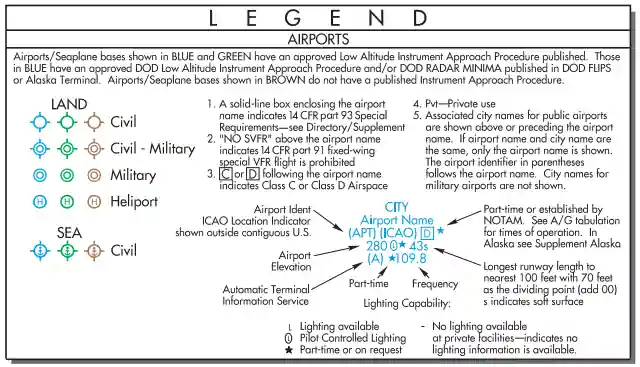
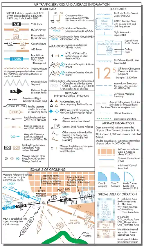
- Airport information is provided in the legend, and the symbols used for the airport name, elevation, and runway length are similar to the sectional chart presentation. []
- Associated city names are shown for public airports only.
- FAA identifiers are shown for all airports.
- ICAO (International Civil Aviation Organization) identifiers are also shown for airports outside of the contiguous United States.
- Instrument approaches can be found at airports with blue or green symbols, while the brown airport symbol denotes airports that do not have instrument approaches.
- Stars are used to indicate the part-time nature of tower operations, Automatic Terminal Information Service (ATIS) frequencies, part-time or on request lighting facilities, and part-time airspace classifications.
- A box after an airport name with a "C" or "D" inside indicates Class C and Class D airspace, respectively.
- On an FAA IFR en route chart, the north arrow on a VOR or NDB compass rose indicates the magnetic-north reference used to orient that NAVAID's compass rose. A VOR compass rose reflects the facility's magnetic orientation, which may differ from the current magnetic variation shown by nearby isogonic lines.
- Jeppesen-specific symbology: On current Jeppesen IFR en route charts, Grid Minimum Off-Route Altitude (Grid MORA) values below 10,000 feet are green, while values of 10,000 feet or higher are maroon. Grid MORA values are expressed in hundreds of feet. This color convention is specific to Jeppesen charts and should not be assumed to apply to FAA charts.
Charted IFR Altitudes
- The minimum en route altitude (MEA) ensures a navigation signal strong enough for adequate reception by the aircraft navigation (NAV) receiver and obstacle clearance along the airway. []
- Communication is not necessarily guaranteed with MEA compliance.
- The obstacle clearance, within the limits of the airway, is typically 1,000' in non-mountainous areas and 2,000' in designated mountainous areas.
- Although the MEA, MOCA, MCA, MRA, and MAA serve different primary purposes, operating at the applicable published altitude on its associated route or segment provides at least the required obstacle clearance: typically 1,000 feet in nonmountainous areas and 2,000 feet in designated mountainous areas.
- MEAs can be authorized with breaks in the signal coverage; if this is the case, the AeroNav Products en route chart notes "MEA GAP" parallel to the affected airway.
- MEAs are usually bidirectional; however, they can be single-directional.
- Arrows are used to indicate the direction to which the MEA applies.
- The minimum obstruction clearance altitude (MOCA), as the name suggests, provides the same obstruction clearance as an MEA; however, the NAV signal reception is ensured only within 22 NM of the closest NAVAID defining the route.
- The MOCA is listed below the MEA and indicated on AeroNav Products charts by a leading asterisk (e.g., "*3400" - see Figure 1-2, V287 at bottom left).
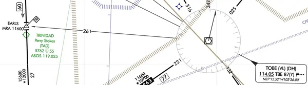
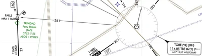
- The minimum reception altitude (MRA) identifies the lowest altitude at which an intersection can be determined from an off-course NAVAID. []
- If the reception is line-of-sight based, signal coverage only extends to the MRA or above.
- However, if the aircraft is equipped with distance measuring equipment (DME) and the chart indicates the intersection can be identified with such equipment, the pilot could define the fix without attaining the MRA.
- On AeroNav Products charts, the MRA is indicated by the symbol. and the altitude preceded by "MRA" (e.g., "MRA 11600").
- The minimum crossing altitude (MCA) is charted when a higher MEA route segment is approached.
- The MCA is usually indicated when a pilot is approaching steeply rising terrain and obstacle clearance and/or signal reception is compromised.
- In this case, the pilot is required to initiate a climb so the MCA is reached by the time the intersection is crossed.
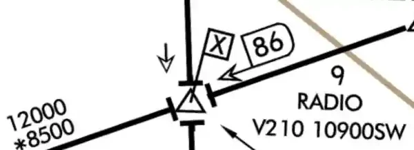
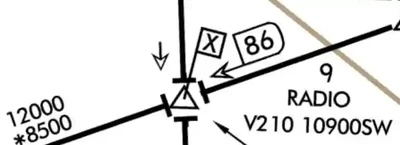
- On AeroNav Products charts, the MCA is indicated by the symbol. , and the Victor airway number, altitude, and the direction to which it applies (e.g. "V210 10900 SW"). []
- The maximum authorized altitude (MAA) is the highest altitude at which the airway can be flown with assurance of receiving adequate navigation signals.
- Flying above the MAA may result in interference from other NAVAIDs on the same or similar frequencies.
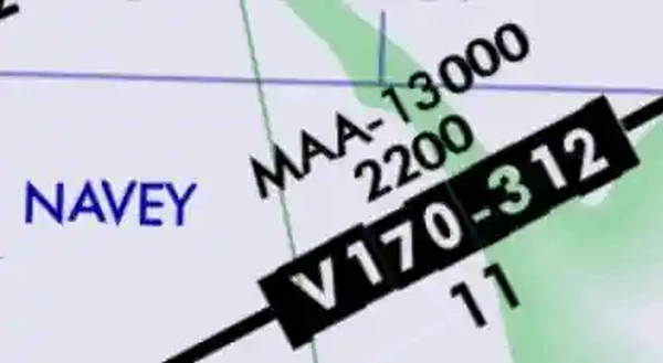
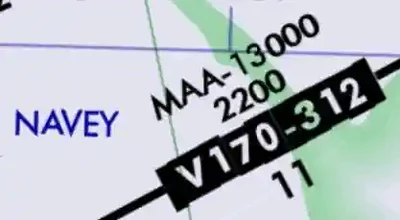
- Chart depictions appear as "MAA-15000." When an MEA, MOCA, and/or MAA change on a segment other than at a NAVAID, a sideways "T" () is depicted on the chart. []
- If there is an airway break without the symbol, one can assume the altitudes have not changed (see the upper left area of Figure 1-2).
- When a change of MEA to a higher MEA is required, the climb may commence at the break, ensuring obstacle clearance.
Types of NAVAIDs
- Very high frequency (VHF) omni-directional ranges (VORs) are the principal NAVAIDs that support the Victor and Jet airways. []
- Many other navigation tools are also available to the pilot.
- For example, non-directional beacons (NDBs) can broadcast signals accurate enough to provide stand-alone approaches, and DME allows the pilot to pinpoint a reporting point on the airway.
- Though primarily navigation tools, these NAVAIDs can also transmit voice broadcasts.
- Tactical air navigation (TACAN) channels are represented as the two- or three-digit numbers following the three-letter identifier in the NAVAID boxes.
- The AeroNav Products terminal procedures provide a frequency-pairing table for the TACAN-only sites. On AeroNav Products charts, very high frequencies and ultra-high frequencies (VHF/UHF (Ultra-High Frequency)) NAVAIDs (e.g., VORs) are depicted in black, while low frequencies and medium frequencies (LF/MF) are depicted as brown. [Figure 1-5].
Identifying Intersections
- Intersections along the airway route are established by a variety of NAVAIDs.
- An open triangle. indicates the location of an ATC reporting point at an intersection.
- If the triangle is solid. , a report is compulsory [Figure 1-4].
- NDBs, localizers, and off-route VORs are used to establish intersections.
- NDBs are sometimes collocated with intersections, in which case passage of the NDB would mark the intersection.
- A bearing to an off-route NDB also can provide intersection identification.
- A localizer course used to identify an intersection is depicted by a feathered arrowhead symbol on the en route chart (.)
- If feathered markings appear on the left-hand side of the arrowhead (.), a back course (BC) signal is transmitted.
- On AeroNav Products en route charts, the localizer symbol is only depicted to identify an intersection.
- Off-route VORs remain the most common means of identifying intersections when traveling on an airway.
- Arrows depicted next to the intersection. indicate the NAVAID to be used for identification.
- Another means of identifying an intersection is with the use of DME
- A hollow arrowhead. indicates DME is authorized for intersection identification.
- If the DME mileage at the intersection is a cumulative distance of route segments, the mileage is totaled and indicated by a D-shaped symbol with a mileage number inside.
- [Figure 1-4] Approved IFR global positioning system (GPS) units can also be used to report intersections.
Other Route Information
- DME and GPS provide valuable route information concerning such factors as mileage, position, and ground speed.
- Even without this equipment, information is provided on the charts for making the necessary calculations using time and distance.
- The en route chart depicts point-to-point distances on the airway system.
- Distances from VOR to VOR are charted with a number inside of a box.
- To differentiate distances when two airways coincide, the word "TO" with the three-letter VOR identifier appear to the left of the distance boxes.
- VOR changeover points (COPs) are depicted on the charts by this symbol.
- The numbers indicate the distance at which to change the VOR frequency.
- The frequency change might be required due to signal reception or conflicting frequencies.
- If a COP does not appear on an airway, the frequency should be changed midway between the facilities.
- A COP at an intersection may indicate a course change.
- Occasionally an "x" appears at a separated segment of an airway that is not an intersection.
- The "x" is a mileage breakdown or computer navigation fix and may indicate a course change.
- Today's computerized system of ATC has greatly reduced the need for holding en route.
- However, published holding patterns are still found on charts at junctures where ATC has deemed it necessary to enable traffic flow.
- When a holding pattern is charted, the controller may provide the holding direction and the statement "as published."
- Boundaries separating the jurisdiction of Air Route Traffic Control Centers (ARTCC) are depicted on charts with blue serrations.
- The name of the controlling facility is printed on the corresponding side of the division line.
- ARTCC remote sites are depicted as blue serrated boxes and contain the center name, sector name, and the sector frequency. [Figure 1-4].
Weather Information and Communication Features
- En route NAVAIDs also provide weather information and serve communication functions.
- When a NAVAID is shown as a shadowed box, an automated flight service station (AFSS) of the same name is directly associated with the facility.
- If an AFSS is located without an associated NAVAID, the shadowed box is smaller and contains only the name and identifier.
- The AFSS frequencies are provided above the box.
- (Frequencies 122.2 and 255.4, and emergency frequencies 121.5 and 243.0 are not listed).
- Without an associated facility, the thin-lined RCO box contains the AFSS name and remote frequency.
- A Remote Communications Outlet (RCO) associated with a NAVAID is designated by a thin-lined box with the controlling AFSS frequency above the box and the name under the box.
- Automated Surface Observing Station (ASOS) and Automated Weather Observing Station (AWOS) are continuously transmitted over selected NAVAIDs and depicted in the NAVAID box.
- ASOS/AWOS are depicted by a white "A" in a solid black circle in the upper right or left corner.
IFR En Route Chart Symbol Reference
Use this study reference with the current chart legend. Chart symbols are condensed representations; always verify the current chart edition, notes, tabulations, and applicable operating rules.
IFR Airports
| Chart cue | Meaning and use |
|---|---|
| On an FAA IFR en route chart, what do blue or green airport symbols indicate compared with brown and black symbols | Blue or green indicates a facility with a published instrument approach procedure and/or radar minima; brown lacks a published instrument procedure or radar minima; black identifies a foreign airport. Airport color on an IFR chart does not use the Sectional's blue-towered/magenta-nontowered convention. |
| What does a boxed C or D following an airport identifier on a low-altitude IFR en route chart indicate | The airport is associated with Class C or Class D airspace, respectively. The box is an airspace-class annotation, not an approach-category or runway code. |
| What does NO SVFR above an airport name on an FAA low-altitude en route chart mean | Fixed-wing special VFR flight is prohibited at that airport. It does not prohibit IFR operations or ordinary VFR in qualifying conditions. |
| How should the L, pilot-controlled-lighting, part-time/on-request, and no-lighting annotations in an IFR airport data block be interpreted | They identify the charted lighting capability and availability; the pilot must distinguish available lighting, pilot control, limited service, and no lighting. The symbols do not guarantee that every runway is lighted or that activation procedures are identical. |
IFR NAVAIDs
| Chart cue | Meaning and use |
|---|---|
| What do black, brown, and blue navigation data generally distinguish on FAA IFR en route charts | Black depicts VHF/UHF data, brown depicts LF/MF data, and blue depicts RNAV data. These colors classify navigation information, not airport tower status. |
| What does the north arrow on a VOR or NDB compass rose indicate on an FAA IFR en route chart | It identifies the magnetic-north reference used to orient that NAVAID's compass rose. A VOR compass rose reflects the facility's magnetic orientation, which may differ from the current magnetic variation shown by nearby isogonic lines. |
| What does the compass-locator-beacon symbol identify on a low-altitude IFR en route chart | A low- or medium-frequency compass locator associated with an instrument procedure or fix. It is not a VOR compass rose or a DME-only facility. |
| What does a feathered ILS localizer-course symbol on an FAA low-altitude en route chart depict | A localizer course providing an additional navigation function, commonly used to define or identify an en route fix. Its presence is not merely a general promise that the airport has an ILS. |
| How is an ILS localizer back course with an additional navigation function distinguished on an FAA low-altitude en route chart | The feathering is shown on the back-course side of the localizer-course depiction. The symbol identifies the back-course signal used for navigation or fix definition; it does not authorize an approach by itself. |
| What do parenthetical codes such as VL, T, L, H, or VH identify in an IFR NAVAID box | The NAVAID's Standard Service Volume classification. The code is not an airway altitude or an aircraft equipment suffix. |
| What does (Y) associated with DME information on an FAA IFR en route chart mean | The DME facility operates in Y mode for reception. It is a DME channel-mode indication, not a statement that RNAV is required. |
IFR Fixes
| Chart cue | Meaning and use |
|---|---|
| How does an FAA IFR en route chart distinguish compulsory from noncompulsory reporting points | A solid triangle is compulsory; an open triangle is noncompulsory or off-airway. Position-reporting requirements still depend on radar contact, ATC instructions, and the applicable rules. |
| How do offset arrows at an IFR fix point relative to the facilities that establish it | An arrow points away from a VHF/UHF NAVAID and toward an LF/MF NAVAID. The arrow indicates the facility forming the fix, not the direction of flight. |
| What does the hollow DME-fix arrow identify on an FAA IFR en route chart | A fix defined by DME distance; an encircled mileage is shown when the distance is not otherwise obvious. It is not a course-direction arrow or a changeover point. |
| What does an x at a mileage breakdown or a five-letter identifier in parentheses represent on an FAA IFR en route chart | A mileage-breakdown point or Computer Navigation Fix; the parenthesized CNF has no ATC function. It is not automatically a compulsory reporting point or clearance limit. |
| What does an encircled route mileage identify on an FAA IFR en route chart | The total mileage between compulsory reporting points or NAVAIDs, as applicable. Segment mileages and total mileage must not be confused when planning fuel or position reports. |
| How are a VHF/UHF radial, an LF/MF bearing, and a magnetic reference bearing oriented on an FAA IFR en route chart | A VHF/UHF radial is outbound from the NAVAID, an LF/MF bearing is inbound to the NAVAID, and a magnetic reference bearing is outbound from the NAVAID or fix. All are magnetic unless the chart states otherwise. |
IFR Communications
| Chart cue | Meaning and use |
|---|---|
| What do R and T following a frequency mean in an FAA IFR en route communication box | R means receive only; T means transmit only. A frequency without either suffix normally supports both transmit and receive, subject to the charted facility. |
| How do the charted stand-alone FSS and RCO boxes differ on FAA IFR en route charts | An FSS box identifies the Flight Service Station; an RCO box identifies a remote communications outlet associated with the controlling FSS, sometimes collocated with an airport. The box style and labels must be read together; reception can depend on altitude and terrain. |
IFR NAVAID Status
| Chart cue | Meaning and use |
|---|---|
| What does an underlined NAVAID frequency or applicable no-voice marking mean on an FAA IFR en route chart | Voice is not transmitted over that NAVAID frequency. The marking does not mean the navigation signal itself is unavailable. |
| What does crosshatching through an IFR NAVAID symbol or box indicate | The NAVAID is in shutdown status. This is different from a part-time or on-request facility. |
| What does the part-time or on-request marking on an IFR NAVAID mean | The facility does not operate continuously or is available on request. Current availability should be verified through chart notes and NOTAMs. |
| What does a greyed NAVAID and NAVAID box on an FAA high-altitude en route chart indicate | The facility is off route relative to the depicted high-altitude route structure. Grey does not by itself mean the NAVAID is shut down; shutdown uses crosshatching. |
IFR Routes
| Chart cue | Meaning and use |
|---|---|
| What does a Victor-airway designator identify on a low-altitude IFR en route chart | A conventional VOR-based low-altitude Federal airway. It is not an RNAV T-route or a high-altitude Jet route. |
| What does a brown LF/MF airway depiction identify on a low-altitude IFR en route chart | A low-frequency or medium-frequency airway based on LF/MF navigation facilities. Brown route data is distinct from black VHF/UHF and blue RNAV data. |
| What does a blue T-route designator identify on an FAA low-altitude en route chart, and what navigation equipment is required | It identifies a low-altitude RNAV route available to appropriately approved GPS or GPS/WAAS-equipped aircraft; Alaska GNSS T-routes require GPS/WAAS equipment. T-routes are depicted from 1,200 feet above the surface, or higher where designated, up to but not including 18,000 feet MSL. They are not TACAN channels or temporary VFR routes. |
| What does a blue TK-route designator identify on an FAA low-altitude en route chart | A low-altitude RNAV helicopter route, with GNSS required as charted. It is not a fixed-wing T-route or an airport taxi route. |
| What does an arrow incorporated into a Victor, Jet, Q, or ATS route depiction indicate | The preferred direction of flight on that route. Preferred direction is not the same as a one-way regulatory prohibition unless another rule or clearance makes it so. |
| What does the unusable-route-segment symbol on an FAA IFR en route chart mean | The depicted airway or route segment is unusable as charted. The pilot must not assume that an airway designation alone makes the segment available. |
| How do IFR en route charts distinguish MTRs five NM or less from routes wider than five NM on either side of centerline | Narrow MTRs use the centerline depiction; wider MTRs use the expanded parallel-line depiction, with an arrow showing route direction. The MTR tabulation and current activity information are needed for altitude and schedule details. |
| What does an Alaska Capstone R-route identify on an FAA en route chart | An RNP 1 route requiring specific FAA authorization and appropriate aircraft lateral-deviation display capability. It is not a generally available Victor airway merely because it appears on the chart. |
| What does a J-route designator identify on an FAA high-altitude en route chart | A conventional high-altitude Jet route. It is distinct from a blue RNAV Q-route. |
| What does a blue Q-route designator identify on an FAA high-altitude en route chart | A high-altitude RNAV route with the navigation and surveillance requirements stated for the region and route. The pilot must verify aircraft eligibility; chart depiction alone does not establish authorization. |
| What does a substitute-route depiction with its supporting data shown in brown mean on an FAA IFR en route chart | A substitute route is available only as described by NOTAM or the appropriate publication. It should not be treated as an ordinary permanently available airway without checking the controlling information. |
IFR Altitudes
| Chart cue | Meaning and use |
|---|---|
| What do arrows associated with an MEA indicate on an FAA IFR en route chart | The direction in which that MEA applies. Without a directional indication, the published MEA normally applies throughout the segment in both directions. |
| What does MEA GAP printed along an airway segment mean | The MEA provides required obstacle clearance, but a gap in navigation signal coverage exists on the segment as charted. It does not waive the MEA or convert the route to uncontrolled airspace. |
| What does MAA followed by an altitude identify on an FAA IFR en route chart | The Maximum Authorized Altitude for the airway or route segment. Above it, adequate navigation reception may not be assured because of interference or other limitations. |
| What does an altitude preceded by an asterisk identify on an FAA low-altitude en route chart | A Minimum Obstruction Clearance Altitude (MOCA). It provides route obstacle clearance but conventional VOR signal coverage is assured only within 22 NM of the facility defining the route segment. |
| What does an MTA annotation at a fix identify | A Minimum Turning Altitude required for specified route-to-route turns at that fix. It is not a general crossing altitude for every aircraft passing the fix. |
| What does an MCA annotation with a route and direction identify | The Minimum Crossing Altitude at which the fix must be crossed when proceeding in the indicated direction. The climb must be planned so the aircraft reaches the MCA by the fix. |
| What does MRA followed by an altitude identify | The Minimum Reception Altitude at which the signals needed to identify the fix can be received. It is a fix-identification altitude, not the minimum altitude for every operation on the segment. |
| What does the sideways altitude-change bar on an FAA IFR en route chart identify | A point other than a NAVAID where the MEA, MOCA, and/or MAA changes. If no change symbol is shown at a route break, do not assume a new altitude merely from the line geometry. |
| What does a VOR changeover-point symbol with mileages identify | The point at which navigation reference should change from one facility to the next; it is omitted at ordinary midpoint changeovers. The mileages show distance to the respective NAVAIDs, not a DME fix requirement by themselves. |
| What does a published holding-pattern racetrack on an FAA IFR en route chart provide | The charted holding fix and pattern orientation, with any depicted maximum holding airspeed applying as annotated. The pilot must still apply the clearance, entry, altitude, timing, and current procedure requirements. |
| What do G and D suffixes associated with high-altitude RNAV MEAs distinguish | G identifies an MEA for GNSS RNAV aircraft; D identifies an MEA for DME/DME/IRU RNAV aircraft. The suffix identifies the navigation basis for the published MEA. |
| What does a large brown two-level number such as 12⁵ represent on a low-altitude IFR en route chart | An Off-Route Obstruction Clearance Altitude, expressed in hundreds of feet MSL for the grid area. OROCA supplies terrain and obstruction clearance margins but does not guarantee NAVAID reception, communications, radar coverage, or controlled-airspace compliance. |
IFR Services
| Chart cue | Meaning and use |
|---|---|
| What does a serrated ARTCC boundary line on an FAA IFR en route chart identify | The boundary between Air Route Traffic Control Center areas; facility names are shown on their respective sides. It is a jurisdiction boundary, not an airway or special-use-airspace boundary. |
| What does a serrated ARTCC remote-site box identify | A remote communications site with the ARTCC name, site or sector information, and discrete frequencies. It is not a stand-alone FSS or an airport tower-frequency box. |
| What does the CPDLC annotation associated with an ARTCC identify | Controller-Pilot Data Link Communications capability for the charted center service. It does not eliminate the need to comply with applicable voice, clearance, and equipment procedures. |
| What does an altimeter-setting-change boundary on an FAA IFR en route chart identify | The point or boundary where the applicable altimeter-setting procedure changes. It is not an MEA change or an ARTCC boundary unless separately depicted. |
IFR Airspace Symbols
| Chart cue | Meaning and use |
|---|---|
| How is Class B airspace depicted on an FAA low-altitude IFR en route chart | As a screened blue area with a solid blue outline. The charted shape and altitude data must be read; the depiction is not the same as the Sectional's unfilled solid-blue boundary alone. |
| What does the MODE C & ADS-B OUT 30 NM depiction on an FAA low-altitude IFR chart identify | The equipment veil around the listed primary airport, subject to the separate transponder and ADS-B Out rules, exceptions, and authorizations. The ring marks the 30-NM equipment-rule area around the listed primary airport. From the surface up to 10,000 feet MSL, the applicable Mode C transponder and ADS-B Out requirements apply, subject to exceptions and ATC-authorized deviations; the Class B boundary and clearance requirement are separate. |
| How is Class C airspace depicted on an FAA low-altitude IFR en route chart | As a screened blue area with a solid blue dashed outline; a boxed C also follows the airport name. This differs from the solid magenta Class C boundary used on a Sectional. |
| How is Class D airspace identified on an FAA low-altitude IFR en route chart | By a boxed D following the airport name; the area itself is generally an open white area on the chart. Do not look for the Sectional's dashed blue Class D boundary convention on the IFR en route chart. |
| What does a screened brown area identify on an FAA IFR en route chart | Class G uncontrolled airspace as described by the chart legend. An open white area is not automatically Class G; on low charts it commonly represents controlled airspace not otherwise screened. |
| How are prohibited, restricted, warning, alert, and military-operations areas identified on FAA IFR en route charts | By their charted special-use-airspace boundaries and P, R, W, A, or MOA designations, with full details in the chart's airspace tabulation. The map label alone is not the complete source for altitudes, times, and controlling-agency information. |
| What does an SFRA boundary on an FAA IFR en route chart identify | A Special Flight Rules Area whose specific operating rules must be obtained from the applicable regulation, chart notes, and current notices. The boundary is not merely advisory and is not interpreted like ordinary special-use airspace. |
IFR Procedural Symbols
| Chart cue | Meaning and use |
|---|---|
| What does an isogonic line and value show on an FAA IFR en route chart | Points of equal magnetic variation. It is not a route centerline or a magnetic course assignment. |
| What time standard applies to times shown on FAA IFR en route charts, and what does a time-zone boundary help interpret | Times are Coordinated Universal Time (UTC); the boundary identifies geographic time-zone changes, with chart notes explaining daylight-saving effects. Local clock time should not be assumed unless a source explicitly says so. |
| What does a match mark on an FAA IFR en route chart help the pilot do | Align adjoining chart panels or chart sheets so route information continues correctly. It is not a compulsory reporting point or a route changeover point. |
IFR Topography
| Chart cue | Meaning and use |
|---|---|
| What does screened terrain depiction on an FAA IFR area chart provide | Topographic context and terrain awareness within the area-chart coverage. It does not replace published minimum altitudes or the pilot's obstacle-clearance planning. |
FAA Aeronautical Chart User's Guide (effective July 9, 2026) is the controlling visual legend used for this reference.
IFR En Route Charts Interactive Scenario
Interactive Scenario
Loading scenario details...
Scenario Complete
IFR En Route Charts Knowledge Check
Choose the knowledge check that matches your current training for IFR En Route Charts.
 Private Pilot
PPL knowledge check
Core Knowledge Review
Review foundational knowledge, key concepts, and practical considerations. Topic: IFR En Route Charts.
- Immediate feedback
- Answer explanations
- Account progress tracking
 Commercial Pilot
CPL knowledge check
Advanced Application
Apply knowledge to advanced operations, risk management, and aeronautical decision-making. Topic: IFR En Route Charts.
- Immediate feedback
- Answer explanations
- Account progress tracking
 Instrument Rating (Airplane)
Instrument knowledge check
Instrument Knowledge
Practice the procedures, systems, weather, and decisions used in instrument flight. Topic: IFR En Route Charts.
- Immediate feedback
- Answer explanations
- Account progress tracking
 Instrument Instructor
CFII knowledge check
Instrument Instructor Knowledge
Review instrument knowledge at the depth expected of an instrument flight instructor. Topic: IFR En Route Charts.
- Immediate feedback
- Answer explanations
- Account progress tracking
Why Take a Quiz?
Quizzes reinforce key concepts, identify knowledge gaps, and build confidence for real-world decisions. Quiz material is representative of the information provided here and is not based on or sourced from the Federal Aviation Administration test bank.
IFR En Route Charts Conclusion
- IFR enroute charts can be obtained through Amazon.
- Still looking for something? Continue searching: