IFR En Route Charts
Instrument navigation relies on precise charted guidance to support safe route selection and obstacle clearance. Understanding IFR en route charts helps pilots interpret airways, minimum altitudes, navigation fixes, and communication information used during instrument flight.
Introduction to IFR En Route Charts
- The objective of IFR en route flight is to navigate within the lateral limits of a designated airway at an altitude consistent with the ATC clearance.
- Your ability to fly instruments safely and competently in the system is greatly enhanced by understanding the vast array of data available to the pilot on instrument charts.
- AeroNav Products maintains and produces the charts for the U.S. Government.
- En route high-altitude charts provide aeronautical information for en route instrument navigation at or above 18,000' MSL.
- Information includes the portrayal of Jet and RNAV routes, identification and frequencies of radio aids, selected airports, distances, time zones, special use airspace, and related information.
- Established jet routes from 18,000' MSL to FL 450 use NAVAIDs not more than 260 NM apart.
- The charts are revised every 56 days.
- To effectively depart from one airport and navigate en route under instrument conditions, a pilot needs the appropriate IFR en route low-altitude chart(s).
- The IFR low altitude en route chart is the instrument equivalent of the sectional chart
- When folded, the cover of the AeroNav Products en route chart displays an index map of the United States showing the coverage areas
- Cities near congested airspace are shown in black type and their associated area chart is listed in the box in the lower left-hand corner of the map coverage box
- Also noted is an explanation of the off-route obstruction clearance altitude (OROCA)
- The effective date of the chart is printed on the other side of the folded chart
- Information concerning MTRs is also included on the chart cover
- The en route charts are revised every 56 days
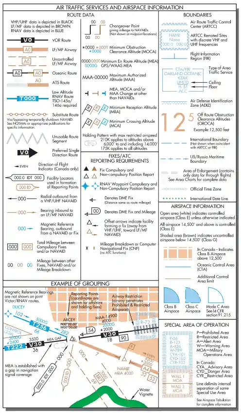
- When the AeroNav Products en route chart is unfolded, the legend is displayed and provides information concerning airports, NAVAIDs, communications, air traffic services, and airspace.
Airport Information
- Airport information is provided in the legend, and the symbols used for the airport name, elevation, and runway length are similar to the sectional chart presentation. [Figure 1]
- Associated city names are shown for public airports only.
- FAA identifiers are shown for all airports.
- ICAO identifiers are also shown for airports outside of the contiguous United States.
- Instrument approaches can be found at airports with blue or green symbols, while the brown airport symbol denotes airports that do not have instrument approaches.
- Stars are used to indicate the part-time nature of tower operations, Automatic Terminal Information Service (ATIS) frequencies, part-time or on request lighting facilities, and part-time airspace classifications.
- A box after an airport name with a "C" or "D" inside indicates Class C and Class D airspace, respectively.
-

En-Route Airport Legend
Charted IFR Altitudes
- The minimum en route altitude (MEA) ensures a navigation signal strong enough for adequate reception by the aircraft navigation (NAV) receiver and obstacle clearance along the airway. [Figure 2]
- Communication is not necessarily guaranteed with MEA compliance
- The obstacle clearance, within the limits of the airway, is typically 1,000' in non-mountainous areas and 2,000' in designated mountainous areas
- MEAs can be authorized with breaks in the signal coverage; if this is the case, the AeroNav Products en route chart notes "MEA GAP" parallel to the affected airway
- MEAs are usually bidirectional; however, they can be single-directional
- Arrows are used to indicate the direction to which the MEA applies
- The minimum obstruction clearance altitude (MOCA), as the name suggests, provides the same obstruction clearance as an MEA; however, the NAV signal reception is ensured only within 22 NM of the closest NAVAID defining the route
- The MOCA is listed below the MEA and indicated on AeroNav Products charts by a leading asterisk (e.g., "*3400" - see Figure 1-2, V287 at bottom left)
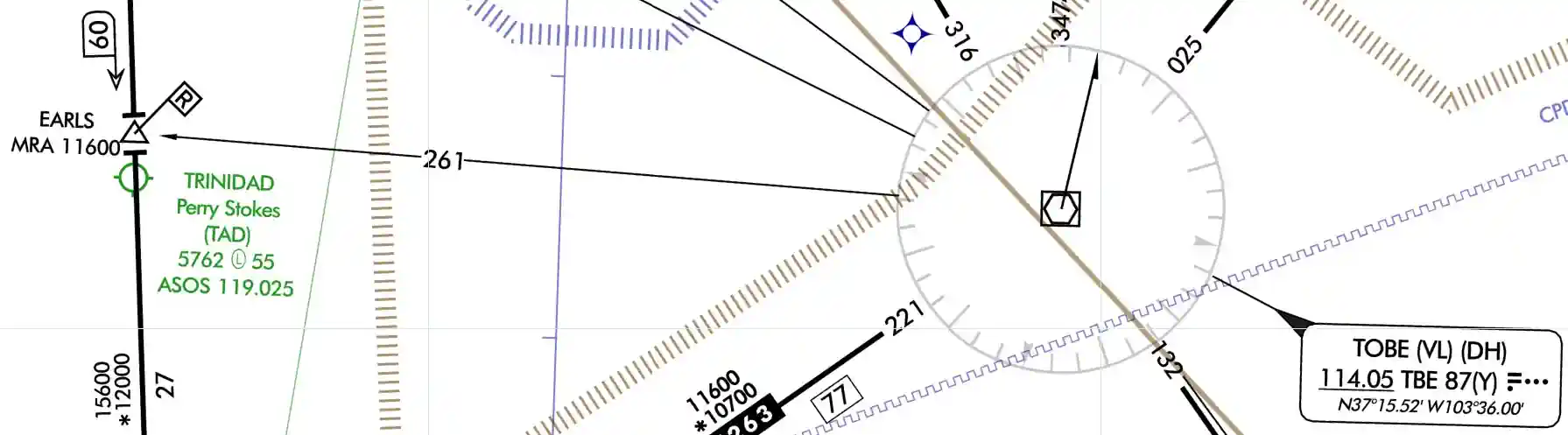
- The minimum reception altitude (MRA) identifies the lowest altitude at which an intersection can be determined from an off-course NAVAID
- If the reception is line-of-sight based, signal coverage only extends to the MRA or above.
- However, if the aircraft is equipped with distance measuring equipment (DME) and the chart indicates the intersection can be identified with such equipment, the pilot could define the fix without attaining the MRA.
- On AeroNav Products charts, the MRA is indicated by the symbol and the altitude preceded by "MRA" (e.g., "MRA 11600"). [Figure 3]
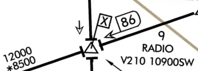
- The minimum crossing altitude (MCA) is charted when a higher MEA route segment is approached.
- The MCA is usually indicated when a pilot is approaching steeply rising terrain and obstacle clearance and/or signal reception is compromised
- In this case, the pilot is required to initiate a climb so the MCA is reached by the time the intersection is crossed
- On AeroNav Products charts, the MCA is indicated by the symbol , and the Victor airway number, altitude, and the direction to which it applies (e.g. "V210 10900 SW") [Figure 4]
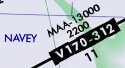
- The maximum authorized altitude (MAA) is the highest altitude at which the airway can be flown with assurance of receiving adequate navigation signals.
- Flying above the MAA may result in interference from other NAVAIDs on the same or similar frequencies.
- Chart depictions appear as "MAA-15000." When an MEA, MOCA, and/or MAA change on a segment other than at a NAVAID, a sideways "T" () is depicted on the chart. [Figure 5]
- If there is an airway break without the symbol, one can assume the altitudes have not changed (see the upper left area of Figure 1-2)
- When a change of MEA to a higher MEA is required, the climb may commence at the break, ensuring obstacle clearance.
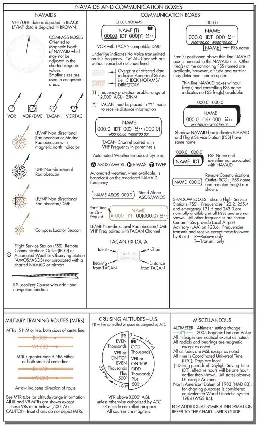
Types of NAVAIDs
- Very high frequency omni-directional ranges (VORs) are the principal NAVAIDs that support the Victor and Jet airways [Figure 3]
- Many other navigation tools are also available to the pilot
- For example, non-directional beacons (NDBs) can broadcast signals accurate enough to provide stand-alone approaches, and DME allows the pilot to pinpoint a reporting point on the airway
- Though primarily navigation tools, these NAVAIDs can also transmit voice broadcasts
- Tactical air navigation (TACAN) channels are represented as the two- or three-digit numbers following the three-letter identifier in the NAVAID boxes
- The AeroNav Products terminal procedures provide a frequency-pairing table for the TACAN-only sites. On AeroNav Products charts, very high frequencies and ultra-high frequencies (VHF/UHF) NAVAIDs (e.g., VORs) are depicted in black, while low frequencies and medium frequencies (LF/MF) are depicted as brown. [Figure 1-5]
-
Instrument Flying Handbook,
Legend from En Route Low Altitude Chart
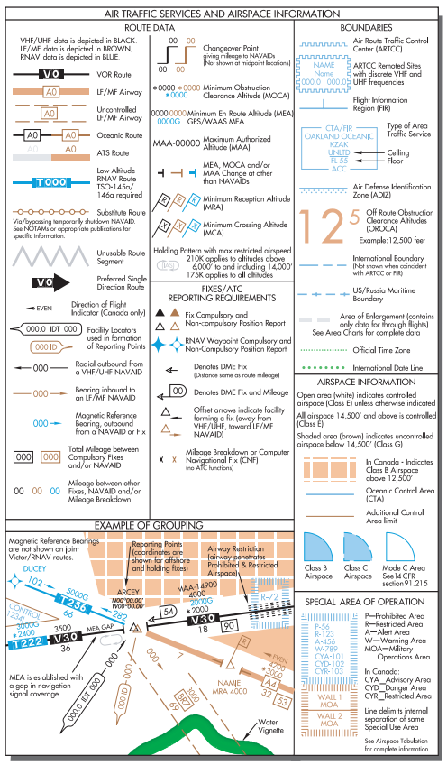
Identifying Intersections
- Intersections along the airway route are established by a variety of NAVAIDs
- An open triangle indicates the location of an ATC reporting point at an intersection
- If the triangle is solid , a report is compulsory [Figure 1-4]
- NDBs, localizers, and off-route VORs are used to establish intersections
- NDBs are sometimes collocated with intersections, in which case passage of the NDB would mark the intersection
- A bearing to an off-route NDB also can provide intersection identification
- A localizer course used to identify an intersection is depicted by a feathered arrowhead symbol on the en route chart ()
- If feathered markings appear on the left-hand side of the arrowhead (), a back course (BC) signal is transmitted
- On AeroNav Products en route charts, the localizer symbol is only depicted to identify an intersection
- Off-route VORs remain the most common means of identifying intersections when traveling on an airway
- Arrows depicted next to the intersection indicate the NAVAID to be used for identification
- Another means of identifying an intersection is with the use of DME
- A hollow arrowhead indicates DME is authorized for intersection identification
- If the DME mileage at the intersection is a cumulative distance of route segments, the mileage is totaled and indicated by a D-shaped symbol with a mileage number inside
- [Figure 1-4] Approved IFR global positioning system (GPS) units can also be used to report intersections
Other Route Information
- DME and GPS provide valuable route information concerning such factors as mileage, position, and ground speed
- Even without this equipment, information is provided on the charts for making the necessary calculations using time and distance
- The en route chart depicts point-to-point distances on the airway system
- Distances from VOR to VOR are charted with a number inside of a box
- To differentiate distances when two airways coincide, the word "TO" with the three-letter VOR identifier appear to the left of the distance boxes
- VOR changeover points (COPs) are depicted on the charts by this symbol
- The numbers indicate the distance at which to change the VOR frequency
- The frequency change might be required due to signal reception or conflicting frequencies
- If a COP does not appear on an airway, the frequency should be changed midway between the facilities
- A COP at an intersection may indicate a course change
- Occasionally an "x" appears at a separated segment of an airway that is not an intersection
- The "x" is a mileage breakdown or computer navigation fix and may indicate a course change
- Today's computerized system of ATC has greatly reduced the need for holding en route
- However, published holding patterns are still found on charts at junctures where ATC has deemed it necessary to enable traffic flow
- When a holding pattern is charted, the controller may provide the holding direction and the statement "as published."
- Boundaries separating the jurisdiction of Air Route Traffic Control Centers (ARTCC) are depicted on charts with blue serrations
- The name of the controlling facility is printed on the corresponding side of the division line
- ARTCC remote sites are depicted as blue serrated boxes and contain the center name, sector name, and the sector frequency. [Figure 1-4]
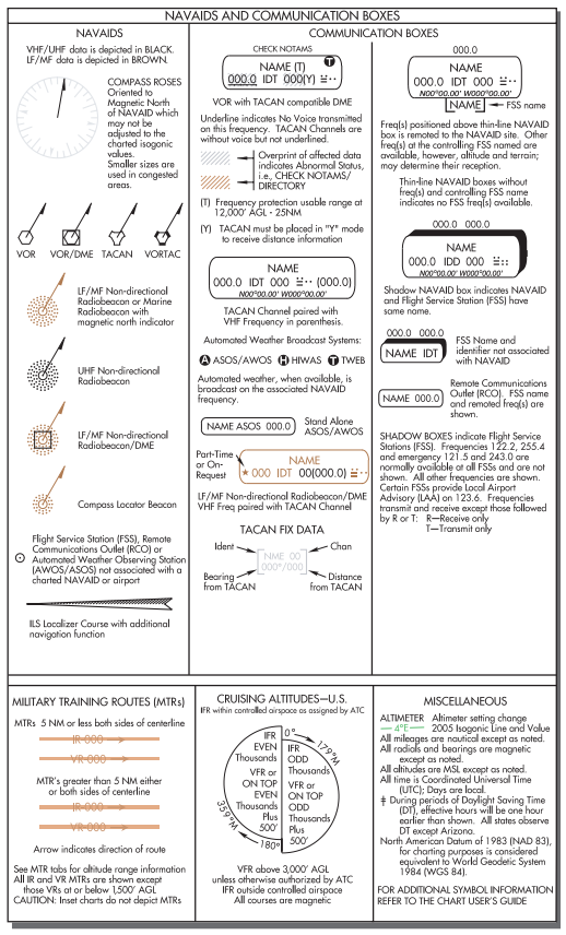
Weather Information and Communication Features
- En route NAVAIDs also provide weather information and serve communication functions
- When a NAVAID is shown as a shadowed box, an automated flight service station (AFSS) of the same name is directly associated with the facility
- If an AFSS is located without an associated NAVAID, the shadowed box is smaller and contains only the name and identifier
- The AFSS frequencies are provided above the box
- (Frequencies 122.2 and 255.4, and emergency frequencies 121.5 and 243.0 are not listed).
- Without an associated facility, the thin-lined RCO box contains the AFSS name and remote frequency
- A Remote Communications Outlet (RCO) associated with a NAVAID is designated by a thin-lined box with the controlling AFSS frequency above the box and the name under the box
- Automated Surface Observing Station (ASOS) and Automated Weather Observing Station (AWOS) are continuously transmitted over selected NAVAIDs and depicted in the NAVAID box
- ASOS/AWOS are depicted by a white "A" in a solid black circle in the upper right or left corner
IFR En Route Charts Conclusion
- IFR enroute charts can be obtained through Amazon
- Still looking for something? Continue searching: