Radar
RADARs use radio waves, transmitted into the air are then received once reflected by an object in the path of the beam.
Introduction to Radar
- ATC uses Radio Detection And Ranging (RADAR) which create radio waves, transmitted into the air that are then received when they have been reflected (echo) by an object in the path of the beam
- Range is determined by measuring the time it takes (at the speed of light) for the radio wave to go out to the object and then return to the receiving antenna
- Direction of a detected object from a radar site is determined by the position of the rotating antenna when the reflected portion of the radio wave is received
- Precision Approach Radars (PARs) may be used as a primary aid, or to monitor approaches
Radar Key Highlights
- Radar systems allow air traffic control to detect, identify, and track aircraft within controlled airspace.
- Primary radar detects aircraft by reflecting radio waves off the aircraft structure without requiring onboard equipment.
- Secondary surveillance radar uses transponder signals to provide aircraft identification and altitude information.
- Radar services improve traffic separation, situational awareness, sequencing, and overall airspace efficiency.
- Controllers use radar information to provide vectors, traffic advisories, weather avoidance assistance, and navigation support.
- Radar coverage limitations can occur due to terrain, altitude, distance, and equipment performance factors.
- Transponders and ADS-B equipment enhance radar surveillance capability and aircraft identification accuracy.
- Pilots receiving radar services remain responsible for complying with air traffic control instructions and maintaining situational awareness.
- Loss of radar contact may require controllers and pilots to transition to non-radar separation procedures.
- Understanding radar operations improves communication effectiveness, IFR navigation, and overall flight safety.
Radar Limitations
- The characteristics of radio waves are such that they normally travel in a continuous straight line unless they are:
- "Bent" by abnormal atmospheric phenomena such as temperature inversions
- Reflected or attenuated by dense objects such as heavy clouds, precipitation, ground obstacles, mountains, etc.
- Screened by high terrain features
- The bending of radar pulses, often called anomalous propagation or ducting, may cause many extraneous blips to appear on the radar operator's display if the beam has been bent toward the ground or may decrease the detection range if the wave is bent upward
- It is difficult to solve the effects of anomalous propagation, but using beacon radar and electronically eliminating stationary and slow moving targets by a method called moving target indicator (MTI) usually negate the problem
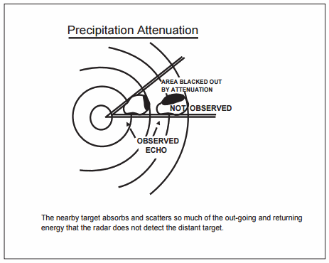
- Radar energy that strikes dense objects will be reflected and displayed on the operator's scope thereby blocking out aircraft at the same range and greatly weakening or completely eliminating the display of targets at a greater range
- Again, radar beacon and MTI are very effectively used to combat ground clutter and weather phenomena, and a method of circularly polarizing the radar beam will eliminate some weather returns
- A negative characteristic of MTI is that an aircraft flying a speed that coincides with the canceling signal of the MTI (tangential or "blind" speed) may not be displayed to the controller
- Relatively low altitude aircraft will not be seen if they are screened by mountains or are below the radar beam due to earth curvature
- The historical solution to screening has been the installation of strategically placed multiple radars, which has been done in some areas, but ADS-B now provides ATC surveillance in some areas with challenging terrain where multiple radar installations would be impractical
- There are several other factors which affect radar control:
- The amount of reflective surface of an aircraft will determine the size of the radar return
- Therefore, a small light airplane or a sleek jet fighter will be more difficult to see on primary radar than a large commercial jet or military bomber
- Here again, the use of transponder or ADS-B equipment is invaluable
- In addition, FAA ATC Facilities display automatically reported altitude information to the controller from appropriately equipped aircraft
- At some locations within the ATC en route environment, secondary-radar-only (no primary radar) gap filler radar systems are used to give lower altitude radar coverage between two larger radar systems, each of which provides both primary and secondary radar coverage. ADS-B serves this same role, supplementing both primary and secondary radar. In those geographical areas served by secondary radar only or ADS-B, aircraft without either transponders or ADS-B equipment cannot be provided with radar service. Additionally, transponder or ADS-B equipped aircraft cannot be provided with radar advisories concerning primary targets and ATC radar-derived weather
-
Wind Turbines:
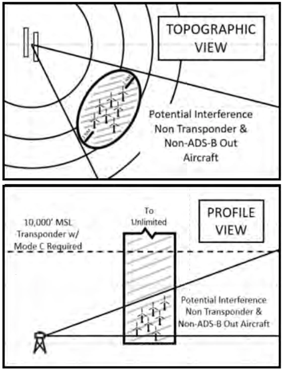
- With regard to air traffic radar reception, wind turbines generally do not affect the quality of air traffic surveillance radar returns for transponder and ADS-B Out equipped aircraft. Air traffic interference issues apply to the search radar and Non-Transponder/Non-ADS-B Out equipped aircraft. Note that generally, one or two wind turbines don't present a significant radar reception loss. A rule of thumb is three (3) or more turbines constitute a wind turbine farm and thus negatively affect the search radar product
- Detection loss in the area of a wind turbine farm is substantial. In extreme circumstances, this can extend for more than 1.0 nautical mile (NM) horizontally around the nearest turbine and at all altitudes above the wind turbine farm. Remember that all aircraft should comply with 14 CFR §91.119(c) "...aircraft may not be operated closer than 500 feet to any person, vessel, vehicle, or structure" [Figure 2]
- To avoid interference Non-Transponder/Non-ADS-B Out equipped aircraft should avoid flight within 1.0 NM horizontally, at all altitudes, from the wind turbine farms
- Because detection loss near and above wind turbine farms for search-only targets causes dropped tracks, erroneous tracks, and can result in loss of separation, it is imperative that Non-Transponder/Non-ADS-B Out equipped aircraft operate at the proper VFR altitudes per hemispheric rule and utilize see-and-avoid techniques
- Pilots should be aware that air traffic controllers cannot provide separation from Non-Transponder/Non-ADS-B Out equipped aircraft in the vicinity of wind turbine farms. See-and-avoid is the pilot's responsibility, as these non-equipped aircraft may not appear on radar and will not appear on the Traffic Information Services-Broadcast (TIS-B)
- With regard to air traffic radar reception, wind turbines generally do not affect the quality of air traffic surveillance radar returns for transponder and ADS-B Out equipped aircraft. Air traffic interference issues apply to the search radar and Non-Transponder/Non-ADS-B Out equipped aircraft. Note that generally, one or two wind turbines don't present a significant radar reception loss. A rule of thumb is three (3) or more turbines constitute a wind turbine farm and thus negatively affect the search radar product
- The controller's ability to advise a pilot flying on instruments or in visual conditions of the aircraft's proximity to another aircraft will be limited if the unknown aircraft is not observed on radar, if no flight plan information is available, or if the volume of traffic and workload prevent issuing traffic information. The controller's first priority is given to establishing vertical, lateral, or longitudinal separation between aircraft flying IFR under the control of ATC
- FAA radar units operate continuously at the locations shown in the Chart Supplement U.S.
- Their services are available to all pilots both civil and military
- Contact the associated FAA control tower or ARTCC on any frequency guarded for initial instructions, or in an emergency, any FAA facility for information on the nearest radar service
Air Traffic Control Radar Beacon System (ATCRBS)
- ATCRBS, sometimes referred to as secondary surveillance radar, consists of three main components:
-
Interrogator:
- Primary radar relies on a signal being transmitted from the radar antenna site and for this signal to be reflected or "bounced back" from an object (such as an aircraft)
- This reflected signal is then displayed as a "target" on the controller's radarscope
- In the ATCRBS, the Interrogator, a ground based radar beacon transmitter-receiver, scans in synchronism with the primary radar and transmits discrete radio signals which repetitiously request all transponders, on the mode being used, to reply
- The replies received are then mixed with the primary returns and both are displayed on the same radarscope
-
Transponder:
- This airborne radar beacon transmitter-receiver automatically receives the signals from the interrogator and selectively replies with a specific pulse group (code) only to those interrogations being received on the mode to which it is set
- These replies are independent of, and much stronger than a primary radar return
-
Radarscope:
- The radarscope used by the controller displays returns from both the primary radar system and the ATCRBS
- These returns, called targets, are what the controller refers to in the control and separation of traffic
-
- The job of identifying and maintaining identification of primary radar targets is a long and tedious task for the controller
- Some of the advantages of ATCRBS over primary radar are:
- Reinforcement of radar targets
- Rapid target identification
- Unique display of selected codes
- A part of the ATCRBS ground equipment is the decoder
- This equipment enables a controller to assign discrete transponder codes to each aircraft under his/her control
- Normally only one code will be assigned for the entire flight
- Assignments are made by the ARTCC computer on the basis of the National Beacon Code Allocation Plan (NBCAP)
- The equipment is also designed to receive Mode C altitude information from the aircraft.
- It should be emphasized that aircraft transponders greatly improve the effectiveness of radar systems
Airport Surface Detection Equipment (ASDE-X)/Airport Surface Surveillance Capability (ASSC)
- Airport Surface Detection Equipment - Model-X (ASDE-X)/ASCC is a multi-sensor surface surveillance system the FAA is acquiring for airports in the United States
- The system provides high resolution, short-range, clutter free surveillance information about aircraft and vehicles, both moving and fixed, located on or near the airport surface under all weather and visibility conditions
- The combination of multiple sensors ensures that the most accurate information about aircraft location is received in the tower, thereby increasing surface safety and efficiency
- The system consists of four main components:
-
Primary Radar System:
- Covers surface to up to 200' above the surface
- Typically located on the Air Traffic Control Tower or other strategic location on the airport
- Able to detect and display aircraft that are not equipped with or have malfunctioning transponders or ADS-B
-
Interfaces:
- Contains an automation interface for flight identification via all automation platforms and interfaces with the terminal radar for position information
-
Automation:
- A Multi-sensor Data Processor (MSDP) combines all sensor reports into a single target which is displayed to the air traffic controller
Air Traffic Control Tower Display:
- A high resolution, color monitor in the control tower cab provides controllers with a seamless picture of airport operations on the airport surface
-
Doppler Radar
- Doppler Radar is a semi-automatic self-contained dead reckoning navigation system (radar sensor plus computer) which is not continuously dependent on information derived from ground based or external aids
- The system employs radar signals to detect and measure ground speed and drift angle, using the aircraft compass system as its directional reference
- Doppler is less accurate than INS, however, and the use of an external reference is required for periodic updates if acceptable position accuracy is to be achieved on long range flights
Surveillance Radar
- Surveillance radars scan through 360 degrees of azimuth and present target information on a radar display located in a tower or center
- This information is used independently or in conjunction with other navigational aids in the control of air traffic
- Surveillance radars are divided into two general categories:
- Airport Surveillance Radar
- Air Route Surveillance Radar
-
Airport Surveillance Radar (ASR):
- Designed to provide relatively short-range coverage in the general vicinity of an airport and to serve as an expeditious means of handling terminal area traffic through observation of precise aircraft locations on a radarscope
- The ASR can also be used as an instrument approach aid
- Enables radar vectors and azimuth in conjunction with approaches
-
Air Route Surveillance Radar (ARSR):
- Long-range system designed primarily to provide a display of aircraft locations over large areas
- Used for en-route traffic
- May be used for terminal operations (approach)
Precision Approach Radar
- Precision Approach Radar (PAR) is a highly accurate system designed for use as a landing aid rather than an aid for sequencing and spacing aircraft but may be used to monitor other types of approaches
- See: Radar Approaches
- PAR is designed to display range, azimuth, and elevation information
- Two antennas are used in the PAR array, one scanning a vertical plane, and the other scanning horizontally
- Since the range is limited to 10 miles, azimuth to 20°, and elevation to 7°, only the final approach area is covered
- Each scope is divided into two parts
- The upper half presents altitude and distance information
- The lower half presents azimuth and distance information
Radar Limitations
- May be unable to issue traffic advisories for aircraft not in control
- Can have interference (clouds, terrain, weather)
- Dense objects can cause blind spots
- Low altitude aircraft may not be seen
- Smaller aircraft have smaller returns
Radar Conclusion
- More reliable maintenance and improved equipment have reduced radar system failures to a negligible factor
- Most facilities actually have some components duplicated, one operating and another which immediately takes over when a malfunction occurs to the primary component
- It is very important however, for the aviation community to recognize the fact that there are limitations to radar service and that ATC controllers may not always be able to issue traffic advisories concerning aircraft which are not under ATC control and cannot be seen on radar
- ASDE-X is useful in identifying areas of concerns, potentially even hotspots, that can be release, like this Safety Alert for Operators regarding high collision risk during runway crossings
- Still looking for something? Continue searching:
Radar References
- Federal Aviation Administration - Pilot/Controller Glossary
- Aeronautical Information Manual (1-1-16) Doppler Radar
- Aeronautical Information Manual (4-1-20) Transponder and ADS-B Out Operation
- Aeronautical Information Manual (4-5-1) Radar
- Aeronautical Information Manual (4-5-2) Air Traffic Control Radar Beacon Code System (ATCRBS)
- Aeronautical Information Manual (4-5-3) Surveillance Radar
- Aeronautical Information Manual (4-5-4) Precision Approach Radar (PAR)
- Aeronautical Information Manual (4-5-5) Airport Surface Detection Equipment (ASDE-X)/Airport Surface Surveillance Capability (ASSC) (ASDE-X)
- CFI Notebook.net - Chart Supplement U.S.
- CFI Notebook.net - Transponder
- Weather Underground - Understanding Weather Radar