Instrument Landing System
The Instrument Landing System (ILS) provides an approach path for precise alignment and descent of an aircraft on final approach to a runway.
Introduction to Instrument Landing System
- The Instrument Landing System provides an approach path for the exact alignment and descent of an aircraft on the final approach to a runway
- The pilot receives guidance information through a ground-based directional transmitter:
- The localizer, providing horizontal guidance, and;
- The glide-slope, providing vertical guidance.
- Landing information is then supplemented with range information through:
- Marker Beacons;
- Compass Locators, or;
- Distance Measuring Equipment, which is simplified via frequency pairing.
- Finally, to aid the transition, visual information is provided through the use of airport lighting
- Other approaches use the same equipment but are similar to localizers, such as Localizer Type Directional Aid Approaches and Simplified Directional Facility Approaches.
- These approaches all come with their unique set of minimums to provide a margin for error and safety buffer to compensate for potential limitations and malfunctions.
- The system is not foolproof, however, and so pilots must be aware of the factors which can cause course distortion to ensure they are receiving reliable signals
- With a background in system function, pilots then perform an instrument landing procedure as published or via radar vectors.
Instrument Landing System Key Highlights
- The Instrument Landing System (ILS) provides precise lateral and vertical guidance for instrument approaches and landings.
- ILS approaches use a localizer for lateral guidance and a glideslope for vertical descent guidance toward the runway.
- Marker beacons, DME, or GPS fixes may provide additional distance and position awareness during ILS operations.
- ILS approaches support low-visibility landings by guiding aircraft along a stabilized approach path to the runway environment.
- Approach minimums vary by ILS category and depend on runway equipment, aircraft capability, and pilot qualifications.
- Pilots must properly identify and monitor localizer and glideslope indications throughout the approach procedure.
- False glideslopes, signal interference, and improper interception angles can affect ILS approach accuracy.
- Approach lighting systems and runway environment cues assist pilots during transition from instrument to visual references.
- ILS critical areas protect signal integrity by limiting aircraft and vehicle movement near sensitive equipment.
- Understanding ILS operation improves instrument approach proficiency, situational awareness, and overall flight safety.
Guidance Information
- Guidance is provided through a ground based system that consists of several components. []
-
Localizer:
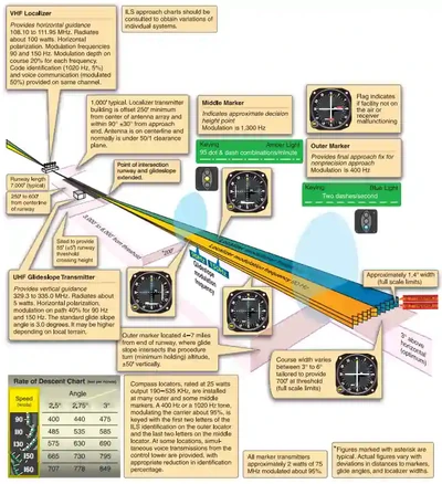
- The localizer (LOC) provides lateral course guidance during an approach to landing.
- Instrumentation operates between 108 - 111.95 MHz on one of 40 channels that transmits from a ground node.
- The localizer's approach course, used with other functional parts (glide-slope, marker beacons, etc.), is called the front course.
- Some localizers may transmit the course line along the extended centerline of a runway, in the opposite direction to the front course, which is called the back course.
- CAUTION:
Unless the aircraft's Instrument Landing System (ILS) equipment includes reverse sensing capability, when flying inbound on the back course, it is necessary to steer the aircraft in the direction opposite the needle deflection when making corrections off-course to on-course. This "flying away from the needle" is also required when flying outbound on the localizer's front course. Do not use back course signals for approach unless there is a published back course approach procedure for that particular runway and Air Traffic Control (ATC) authorizes the approach.
- The localizer's approach course, used with other functional parts (glide-slope, marker beacons, etc.), is called the front course.
- The localizer signal transmits at the far end of the runway.
- Adjusted for a course width of (full-scale fly-left to a full scale fly-right) of 700' at the runway threshold.
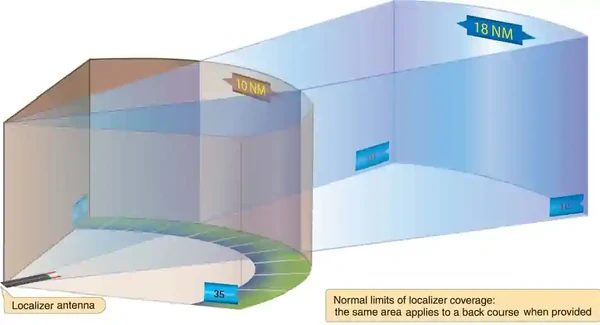
- The localizer provides course guidance throughout the descent path to the runway threshold from a distance of 18 Nautical Miles (NM) from the antenna between an altitude of 1,000 feet above the highest terrain along the course line and 4,500 feet above the elevation of the antenna site.
- Proper off-course indications are provided throughout the following angular areas of the operational service volume: []
- To 10° on either side of the course along a radius of 18 NM from the antenna; and.
- From 10 to 35° on either side of the course along a radius of 10 NM.
- Unreliable signals may be received outside of operational service volume areas.
- ATC may clear aircraft on procedures beyond the service volume when the controller initiates the action or when the pilot requests, and radar monitoring is provided.
- The areas described and depicted in [] represent a Standard Service Volume (SSV) localizer
- All charted procedures with localizer coverage beyond the 18 NM SSV have been through the approval process for Expanded Service Volume (ESV) and validated by flight inspection. []
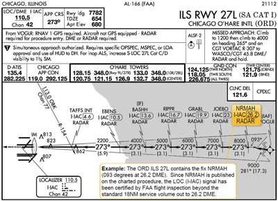
- Identification is in International Morse Code and consists of a three-letter identifier preceded by the letter I (- -) transmitted on the localizer frequency.
- Three letter id preceded by I (i.e., I-DAB)
- The approach plate displays the Morse code pattern.
-
Glide-Slope/Glide Path:
- The UHF glide-slope transmitter, operating on one of the 40 ILS channels within the frequency range 329.15 MHz to 335.00 MHz radiates its signals in the direction of the localizer front course.
- The term glide path means that portion of the glide-slope that intersects the localizer.
- CAUTION: False glide-slope signals may exist in the area of the localizer back course approach, which can cause the glide-slope flag alarm to disappear and present unreliable glide-slope information. Disregard all glide-slope signal indications when making a localizer back course approach unless the approach and landing charts specify a glide-slope.
- The transmitter is located 750 - 1,250' from the approach end offset 250 - 650' from centerline.
- It transmits a glide-path beam 1.4° wide (vertically).
- The signal is considered accurate down to the lowest decision height (DH) published on an ILS approach procedure.
- Any reference to glide-path indications below that height is supplemented by visual reference to the runway environment.
- Glide-paths with no published DH are usable to runway threshold.
- The glide-slope is normally usable to a distance of 10 NM.
- However, at some locations, the glide-slope has been certified for an extended service volume that exceeds 10 NM.
- Be alert for false glide-slopes and reverse sensing when intercepting the glide-slope.
- False courses and reverse sensing can occur when intercepting the ILS at angles considerably greater than the published path.
- It is therefore extremely important to maintain glide-slope to assure obstacle/terrain clearance is maintained.
- The published glide-slope threshold crossing height (TCH) DOES NOT represent the height of the actual glide path on-course indication above the runway threshold.
- It is a reference for planning purposes which represents the height above the runway threshold that an aircraft's glide-slope antenna should be if that aircraft remains on a trajectory formed by the four-mile-to-middle marker glide-path segment.
- TCH does not coincide with GS altitude over threshold, but rather with the antennas should be (think bigger aircraft)
- Pilots must be aware of the vertical height between the aircraft's glide-slope antenna and the main gear in the landing configuration and, at the DH, plan to adjust the descent angle accordingly if the published TCH indicates the wheel crossing height over the runway threshold may not be satisfactory.
- Tests indicate a comfortable wheel crossing height is approximately 20 to 30', depending on the type of aircraft.
- TCH for a runway is established based on several factors, including the largest aircraft category that normally uses the runway, how airport layout affects the glide-slope antenna placement, and terrain. A higher than optimum TCH, with the same glide path angle, may cause the aircraft to touch down further from the threshold if the approache's trajectory is maintained until the flare. Pilots should consider the effect of a high TCH on the runway available for stopping the aircraft.


Range Information
-
Distance Measuring Equipment:
- When installed with the ILS and specified in the approach procedure, Distance Measuring Equipment (DME) may be used:
- In lieu of the Outer Marker (OM);
- As a back course (BC) Final Approach Fix (FAF); and.
- To establish other fixes on the localizer course.
- In some cases, DME from a separate facility may be used within Terminal Instrument Procedures (TERPS) limitations:
- To provide an arc for the initial approach segment;
- FAF for BC approaches; and.
- Substitute for OM.
- When installed with the ILS and specified in the approach procedure, Distance Measuring Equipment (DME) may be used:
-
Marker Beacons:
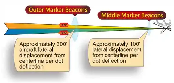
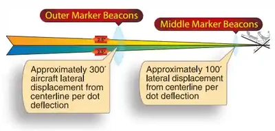
- ILS marker beacons have a rated power output of 3 watts or less and an antenna array designed to produce an elliptical pattern with dimensions, at 1,000 feet above the antenna, of approximately 2,400 feet in width and 4,200 feet in length.
- Airborne marker beacon receivers with a selective sensitivity feature should always be operated in the "low" sensitivity position for proper reception of ILS marker beacons.
- ILS systems may have an associated OM. A Middle Marker (MM) is no longer required. Locations with a Category II ILS also have an Inner Marker (IM).
- Due to advances in both ground navigation equipment and airborne avionics, as well as the numerous means that may substitute a marker beacon, the current requirements for the use of marker beacons are:
- An OM or suitable substitute identifies the FAF for non-precision approach (NPA) operations (for example, localizer only); and.
- The MM indicates a position approximately 3,500 feet from the landing threshold. This is also the position where an aircraft on the glide path will be at an altitude of approximately 200 feet above the touchdown zone's elevation. An MM is no longer operationally required. There are some MMs still in use, but no MMs are being installed at new ILS sites by the FAA; and.
- An IM, where installed, indicates the point at which an aircraft is at decision height on the glide path during a Category II ILS approach. An Initial Marker (IM) is only required for CAT II operations that do not have a published radio altitude (RA) minimum.
- Due to advances in both ground navigation equipment and airborne avionics, as well as the numerous means that may substitute a marker beacon, the current requirements for the use of marker beacons are:
- A back course marker normally indicates the ILS back course final approach fix where approach descent is commenced.
- The following means may be used to substitute for the OM:
- Compass locator; or.
- Precision Approach Radar (PAR); or.
- Airport Surveillance Radar (ASR); or.
- DME, Very-High Frequency Omni-directional Range (VOR) radial intersections or Nondirectional Beacon (NDB) fixes authorized in the Standard Instrument Approach Procedure; or.
- A suitable RNAV system with a Global Positioning System (GPS), capable of fix identification on a Standard Instrument Approach Procedure.
-
Compass Locator:
- Similar to an NDB, a compass locator is a low to medium powered beacon, which is the precursor to modern-day marker beacons
- Compass locators provide the same basic information to the pilot as a marker beacon
- Compass locator transmitters are often situated at the MM and OM sites.
- The transmitters have a power of less than 25 watts, a range of at least 15 miles, and operate between 190 and 535 kHz.
- At some locations, higher-powered radio beacons, up to 400 watts, are used as OM compass locators.
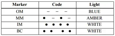
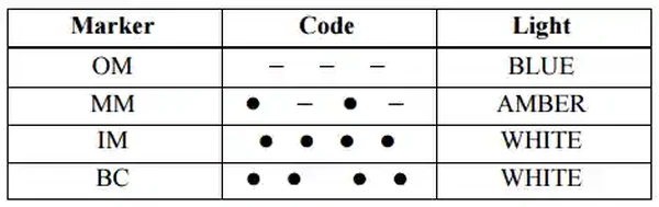
- Compass locators transmit two-letter identification groups. []
- The outer locator transmits the first two letters of the localizer identification group, and the middle locator transmits the last two letters of the localizer identification group.
- Provide a transition from en-route to approach phase
- The transmitters have a power of less than 25 watts, a range of at least 15 miles, and operate between 190 and 535 kHz
- At some locations, higher-powered radio beacons, up to 400 watts, are used as OM compass locators
- OM: First 2 letters of loc id group
- MM: Last 2 letters of loc id group
ILS Frequency Pairs
- The ILS pairs frequencies to give localizer and glide-slope information on a single frequency
- As far as the pilot is concerned, you only need to input the Very-High Frequency (VHF) frequency, as the Ultra-High Frequency (UHF) is automatically tied to that
- This single ILS frequency is found in the top left of the approach plate
- The list of paired frequencies is in the Aeronautical Information Manual under paragraph 1-1-9, Instrument Landing System
Localizer Type Directional Aid
- The LDA is of comparable use and accuracy to a localizer but is not part of a complete ILS
- The LDA course usually provides a more precise approach course than the similar Simplified Directional Facility (SDF) installation, which may have a course width of 6 or 12°
- LDAs are not aligned with the runway
- If less than 30° off, straight in minimums are published
- If more than 30° off, circle to land minimums are published
- Some approaches have glide-slopes referred to Approaches with Vertical Guidance (APVs).
- APVs are annotated in the plan view of the instrument approach chart with a note, "LDA/Glide-slope".
- These procedures fall under a newly defined category of approaches called Approaches with Vertical Guidance (APV).
- LDA minima for with and without glide-slope (GS) is provided and annotated on the minima lines of the approach chart as S-LDA/GS and S-LDA.
- Because the final approach course is not aligned with the runway centerline, additional maneuvering will be required compared to an ILS approach.
- Note that approaches with vertical guidance are just that, guidance.
- These approaches are non-precision approaches, not precision.
Simplified Directional Facility
- The SDF provides a final approach course similar to that of the ILS localizer but no glide-slope information
- Operates on the same localizer frequency (108.10 to 111.95)
- Techniques and procedures used in an SDF instrument approach are the same as those in a localizer, except the final approach course may not be aligned with the runway, and the course may be wider, resulting in less precision.
- Note that as the approach course originates at the antenna site, an approach that flown beyond the runway threshold will lead the aircraft to the SDF offset position rather than along the runway centerline.
- Usable to 35° on either side of course line, same as a localizer.
- Any signals received outside of this range shall be considered unusable for navigation.
- The antenna may be offset from the runway centerline, and so the final approach course and the runway bearing should be referenced on the IAP chart.
- Normally not more than 3°; however, if the approach continues beyond the runway threshold, you will be in a bad position to land.
- The signal is fixed at either 6 or 12° as necessary to provide maximum fly-ability and optimum course quality
- Identification is provided through a 3-letter Morse code indicated on the instrument approach chart for a particular airport
ILS Minimums
- The lowest authorized ILS minimums, with all required ground and airborne systems components operative, are:
-
Category (CAT) I:
- Decision Height (DH): 200'.
- Runway Visual Range (RVR): 2,400' (1,800 w/ Touch Down Zone (TDZ) and centerline lighting) or (with Autopilot or Flight Director (FD) or Heads Up Display (HUD), RVR 1,800').
-
Category (CAT) II:
- DH: 100'
- RVR: 1,200' with auto-land or HUD to touchdown and noted on authorization, RVR 1,000'.
-
Category (CAT) IIIa:
- No DH or DH below 100'.
- RVR not less than 700'.
-
Category (CAT) IIIb:
- No DH or DH below 50'.
- RVR Less than 700' but not less than 150'.
-
Category (CAT) IIIc:
- No DH.
- No RVR minimum.
- Note that special authorization and equipment required for Categories II and III
ILS Limitations and Malfunctions
-
Inoperative ILS Components:
Inoperative localizer:
ILS not authorized.Inoperative glide-slope:
ILS reverts to a non-precision, localizer approach if you have a failure of the GS after the FAF inform the controller you are switching to a localizer approach while climbing or descending to the Minimum Descent Altitude (MDA) (no longer a DH).- See the inoperative component table in the U.S. Government Terminal Procedures Publication (TPP) for adjustments to minimums due to inoperative airborne or ground system equipment.
-
ILS Course Distortion:
- All pilots should be aware that ILS installations are subject to signal interference by surface vehicles and aircraft (either on the ground or airborne).
- ILS CRITICAL AREAS are established near each localizer and glide slope antenna
- Pilots should be aware of the level of critical area protection they can expect in various weather conditions and understand that signal disturbances may occur as a result of normal airport operations irrespective of the official weather observation.
- When in use, these areas require the pilot to keep the entire aircraft clear of the associated marking and remain on the safe side of the ILS Critical Area.
- ATC is not always required to issue control instructions to avoid interfering operations within ILS critical areas at controlled airports during the hours the Airport Traffic Control Tower (ATCT) is in operation.
- ATC responsibilities vary depending on the official weather observation and are described as follows:
-
Weather Conditions (greater than 800' and 2 miles visibility):
- When official weather observation indicates a ceiling of 800 feet or higher and visibility 2 miles or greater, no localizer or glideslope critical area protection is provided by ATC unless specifically requested by the flight crew.
-
Weather Conditions (less than 800' or 2 miles visibility):
- When official weather observation indicates a ceiling of less than 800 feet or visibility less than 2 miles:
-
Holding:
- Aircraft holding below 5,000 feet between the outer marker and the airport may cause localizer signal variations for aircraft conducting the ILS approach.
- Accordingly, such holding will not be authorized by ATC.
- Aircraft holding below 5,000 feet between the outer marker and the airport may cause localizer signal variations for aircraft conducting the ILS approach.
-
Localizer Critical Area:
- When an arriving aircraft is inside the outer marker (OM) or the fix used in lieu of the OM, vehicles and aircraft will not be authorized in or over the precision approach critical area except:
- A preceding arriving aircraft on the same or another runway may pass over or through the localizer critical area, and;
- A preceding departing aircraft or missed approach on the same or another runway may pass through or over the localizer critical area.
- When an arriving aircraft is inside the outer marker (OM) or the fix used in lieu of the OM, vehicles and aircraft will not be authorized in or over the precision approach critical area except:
-
Glide Slope Critical Area:
- ATC will not authorize vehicles or aircraft operations in or over the glideslope critical area when an arriving aircraft is inside the outer marker (OM), or the fix used in lieu of the OM, unless the arriving aircraft has reported the runway in sight and is circling or side-stepping to land on another runway.
-
- When official weather observation indicates a ceiling of less than 800 feet or visibility less than 2 miles:
-
Weather Conditions (less than 200' ceiling or 2000' RVR:
- When Official weather observation indicates a ceiling less than 200 feet or runway visual range (RVR) less than 2000 feet:
-
Localizer Critical Area:
- In addition to the critical area protection described above, when an arriving aircraft is inside the middle marker (MM), or in the absence of a MM, 1/2 mile final, ATC will not authorize:
- A preceding arriving aircraft on the same or another runway to pass over or through the localizer critical area, or;
- A preceding departing aircraft or missed approach on the same or another runway to pass through or over the localizer critical area.
- In addition to the critical area protection described above, when an arriving aircraft is inside the middle marker (MM), or in the absence of a MM, 1/2 mile final, ATC will not authorize:
-
- When Official weather observation indicates a ceiling less than 200 feet or runway visual range (RVR) less than 2000 feet:
- To ensure that pilot and controller expectations match with respect to critical area protection for a given approach and landing operation, a flight crew should advise the tower any time it intends to conduct any autoland operation or use an SA CAT I, any CAT II, or any CAT III line of minima anytime the official weather observation is at or above a ceiling of 800 feet and 2 miles visibility
- If ATC is unable to protect the critical area, they will advise the flight crew.
- Pilot: "Denver Tower, United 1153, Request [Autoland/Coupled] Approach [Runway]"
- ATC: "United 1153, Denver Tower, Roger, Critical Areas not protected"
- Pilots are cautioned that even when the critical areas are considered to be protected, unless the official weather observation including controller observations indicates a ceiling less than 200 feet or RVR less than 2000 feet, ATC may still authorize a preceding arriving, departing, or missed approach aircraft to pass through or over the localizer critical area and that this may cause signal disturbances that could result in an undesired aircraft state during the final stages of the approach, landing, and rollout
- Pilots are cautioned that vehicular traffic not subject to ATC may cause momentary deviation to ILS course or glide slope signals.
- Also, critical areas are not protected at uncontrolled airports or at airports with an operating control tower when weather or visibility conditions are above those requiring protective measures. Aircraft conducting coupled or autoland operations should be especially alert in monitoring automatic flight control systems and be prepared to intervene as necessary. []
- Unless otherwise coordinated through Flight Standards, ILS signals to Category I runways are not flight inspected below the point that is 100 feet less than the decision altitude (DA).
- Guidance signal anomalies may be encountered below this altitude
Instrument Landing System Procedure
- Request the ILS approach from ATC
- Follow the assigned clearance or radar vectors, as assigned by ATC
- Complete any appropriate checklists, ensuring the aircraft is in the landing configuration before intercepting the glide-slope
- Upon intercepting the glide-slope (FAF), reduce power,. and adjust pitch. to maintain glide-slope
- The glideslope angle is on the instrument approach chart, generally around 3°
- Whatever 3° corresponds to on your vertical speed indicator relative to your ground speed is a good place to start
- Make small adjustments as required
- Corrections will become more sensitive as you get closer to the airport, so it is imperative to stabilize your approach as early as possible
- To recapture the glideslope, corrections should be within a degree or two of pitch, or a couple of hundred feet per minute on the rate of descent
- To recapture the localizer, stay inside of the heading bug, if available, or 5 degrees left or right of center if none is
- At the OM or Locator Outer Marker (LOM):
- Check the altimeter crossing the OM/LOM
- Perform the 5Ts:
- Time: Note the time
- Turn: to track the inbound course
- Twist: Verify the Omni Bearing Selector (OBS) is set to inbound course:
- Throttle: Maintain approach speed.
- Talk: Make required reports
- At 1000' above DA(H), call out "1000 above DA(H)"
- At 500' above DA(H), call out "500 above DA(H)," and complete a "GUMP" (Gas, Undercarriage, Mixture, Propeller) check
- At 100' above DA(H), call out "100 above DA(H)"
- Upon reaching DA(H):
- Continue the approach if the runway environment is in sight, or;
- Descend no lower than 100 above touchdown zone elevation when referencing the approach light system without seeing the red terminating bars or red side-row bars
- Call out "missed approach," and execute the published missed approach procedure if ATC does not direct a different procedure
- Continue the approach if the runway environment is in sight, or;
- With the runway in sight and when in a position from which a descent to a landing on the indented runway can be made at a normal rate of descent using normal maneuvers
- Callout (over the ICS), "Runway in Sight, Landing"
- Maintain the localizer and glideslope during the visual descent to a point over the runway where the a normal landing can be performed
- At or below VFE, set the flaps as appropriate for landing
Radar Vectors
- On dogleg to final when within 5-7 NM of the FAF execute the above procedures accomplish the same procedures as above starting with step 6
- If above the localizer minimums and you lose glide-slope then you may request the localizer if you lost a localizer approach, however, if you lose glide-slope below localizer minimums, go mist and if you lose the localizer in any situation, go missed
Instrument Landing System Knowledge Check
Private Pilot

Core Knowledge Review
Review the foundational knowledge, key concepts, and practical considerations for Instrument Landing System.
Foundational
Immediate Feedback
Answer Explanations
Commercial Pilot

Advanced Application
Apply your knowledge of Instrument Landing System to advanced operational scenarios, risk management, and aeronautical decision-making.
Advanced
Scenario Based
Risk Management
Why Take a Quiz?
Quizzes reinforce key concepts, identify knowledge gaps, and build confidence for real-world decisions in the cockpit.
Instrument Landing System Interactive Scenario
Interactive Scenario
Loading scenario details...
Decision 1
0%
Scenario Complete
Instrument Landing System Conclusion
- The components of an ILS can be remembered by GLAM (Glideslope, Localizer, Approach Lights, and Marker Beacons
- Some final approach fixes may be designated with cross radials using VORs, however, de-selecting the ILS is NOT an acceptable method of identifying the FAF
- Where a complete ILS system is installed on each end of a runway; (i.e., the approach end of Runway 4 and the approach end of Runway 22), the ILS systems are not in service simultaneously
- Pilots should be aware of the possibility of momentary erroneous indications on cockpit displays when the primary signal generator for a ground-based navigational transmitter is inoperative.
- Pilots should disregard any navigation indication, regardless of its apparent validity, if designated inoperative by Notice to Airmen.
- See also:
- Ground control will advise you when to hold short of critical areas.
- Safety works best when we help each other, so if the weather is at or below 800' or 2 miles and ATC hasn't issued you an ILS hold, it doesn't hurt to hold short and ask anyway.
- Remember, ILS Critical Areas are only mandatory when ATC issues a hold. If the field is uncontrolled, there is no requirement to hold short of the ILS Critical Area.
- That said, be mindful of the weather and inbound aircraft, and consider holding short if conditions warrant.
- Remember, the FAA requests user reports on NAVAID outages.
- Review your ILS knowledge by taking the Air Safety Institute's "The Almost ILS" quiz
- Review your instrument landing safety knowledge by taking the Air Safety Institute's "LDA into Hartford" quiz
- Still looking for something? Continue searching:
Instrument Landing System References
- Federal Aviation Administration - Pilot/Controller Glossary.
- Aeronautical Information Manual (1-1-9) Instrument Landing System (ILS).
- Aeronautical Information Manual (1-1-10) Simplified Directional Facility (SDF).
- Aeronautical Information Manual (5-4-5) Instrument Approach Procedure Charts.
- Aeronautical Information Manual (5-4-13) ILS Approaches to Parallel Runways.
- Aeronautical Information Manual (5-4-14) Parallel ILS/MLS Approaches (Dependent).
- Aeronautical Information Manual (5-4-15) Simultaneous Parallel ILS/MLS Approaches (independent).
- Instrument Flying Handbook (9-35) Instrument Landing System (ILS).