Descent & Landing Performance
Descent and landing performance determine how safely an aircraft transitions from cruise to touchdown. Pilots must understand glide planning, approach energy management, environmental effects, and landing distance calculations.
Introduction to Descent & Landing Performance
- Expected landing performance drives airfield suitability decisions and impacts the conduct of the approach and landing.
- Landing performance starts with the descent.
- Landing distance depends on several factors, most of which are based on engineering data and can be determined by referencing performance charts.
- Some variables must be considered, such as:
- Balancing all these variables yields a series of best practices for achieving optimal landing performance.
- Still, the pilot can affect performance through techniques such as slips to landing, whether it is through forward or side slips.
- Finally, on the approach, determining the approach rate of descent.
- Think you've got a solid understanding of landing performance? Don't miss the landing performance quiz below and the topic summary.
WARNING:
All procedures are GENERALIZED.
Use the Pilot Operating Handbook (POH) procedures for specific aircraft performance and limitations.
and/or current Standard Operating Procedures (SOPs).
Descent & Landing Performance Key Highlights
- Descent and landing performance are affected by aircraft weight, configuration, atmospheric conditions, runway characteristics, and pilot technique.
- Proper descent planning helps ensure stabilized approaches, efficient energy management, and safe landing operations.
- Flap configuration increases drag and lift, allowing steeper descent angles and lower landing speeds.
- Excessive airspeed during approach increases landing distance and reduces safety margins during touchdown and rollout.
- Density altitude, temperature, wind, runway slope, and surface conditions directly affect landing performance calculations.
- Headwinds generally reduce landing distance, while tailwinds significantly increase required runway length.
- Landing distance performance data published in the Pilot’s Operating Handbook (POH) should be adjusted for actual operating conditions.
- Stabilized approaches improve landing consistency by maintaining appropriate airspeed, descent rate, alignment, and aircraft configuration.
- Go-arounds should be initiated whenever a safe landing cannot be assured due to unstable approach conditions or runway hazards.
- Effective descent and landing planning supports safe runway operations, aircraft control, and aeronautical decision-making.
Descent Planning
- Planning for descent ensures the accurate and timely arrival at the desired space in time, typically to prepare for landing.
- Pilots often chose between maintaining power during the descent, pitching forward to achieve a faster airspeed, or reducing power during the descent to maintain a desired airspeed.
- While differences in aircraft, avionics, and technique flown exist, the 60:1 rule allows for basic in-flight calculations in preparation for descent.
-
Descent Planning With The 60-to-1 Rule:
- The 60 to 1 rule states that for every 1 degree of shift (up/down/left/right), an offset of 100 feet per 1 Nautical Mile (NM) occurs.
- As it relates to descent planning, this means that for every 1° the pitch is lowered (relative to level flight), you will lose 100 feet every NM.
-
Practical Application:
- Example: A pilot is 20 NM away from an airport at 6,000' MSL to enter the downwind at 1000' Mean Sea Level.
-
Determining Pitch Angle:
- We have 5,000' to lose over 20 NM.
- If we take the altitude loss and divide it by the distance (5,000'/20NM), we see that we need to lose 250 feet for every 1 NM.
- Referencing the 60-to-1 rule, if a 1-degree pitch down is 100' per 1 NM, then a 2.5-degree pitch down is 250' per 1 NM.
-
Determining Vertical Speed:
- We determined that our pitch must be 2.5 degrees down. Since we're flying at a constant speed, this translates to a predictable vertical speed, which we can calculate.
- If you multiply the descent angle (2.5 degrees in the above example) by the Nautical Miles-per-minute and then multiply that number by 100, you get the Feet Per Minute (FPM) descent rate.
- Shown another way: (NM per Min * Pitch down * 100 = Descent in Feet per Minute).
- First, determine nautical miles per minute:
- Divide the airspeed (NM per Hour) by 60 (Minutes per hour) to get Nautical Miles per minute.
- If we intend to descend at 90 knots, we divide that by 60 and get 1.5 NM per minute.
- Second, determine vertical speed:
- If we then multiply our NM per minute by our pitch-down of 2.5 degrees, we get 3.75.
- Multiply 3.75 by 100, and you get 375 feet per minute.
- Another way to achieve the same result is to recognize that we have 20 NM to travel at 1.5 NM/Minute; this allows us to determine that we have approximately 13 minutes to lose 5,000 feet.
- 5000 divided by 13 = 384 FPM.
-
Working Backward:
- We can work backward, too.
- For example, let's say we wish to descend at 200 FPM for passenger comfort.
- If we are traveling at 1.5 NM per minute, and we have 5,000' to lose at 200 FPM, it will take 25 minutes to accomplish this descent (5,000'/200 FPM).
- Since we calculated that ~375 FPM was required to be 20 NM out, and we plan to reduce our rate of descent, we need to begin descending earlier.
- Assuming we are flying at 1.5 NM per minute and need 25 minutes to descend, we must begin our descent 37.5 NM away (25 minutes* 1.5 NM per minute).
- Additionally, instrumentation may indicate the distance of the aircraft from a known point.
- If instrumentation displays 5 minutes to a point, and the pilot needs to descend 1000' in that time, then feet (1,000) divided by minutes (5) equals the required feet per minute, in this case 200 feet per minute.
- If we are traveling at 1.5 NM per minute, and we have 5,000' to lose at 200 FPM, it will take 25 minutes to accomplish this descent (5,000'/200 FPM).
- Note that the 60-to-1 rule is a guideline, not an exact science, but it is accurate enough to inform basic decisions and verify expected performance.
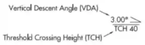
- When flying a non-precision approach, a Vertical Descent Angle (VDA) and Threshold Crossing Height (TCH) may be published. For copter approach procedures, a Heliport Crossing Height (HCH) replaces the TCH. The VDA is strictly advisory and provides a means to establish a stabilized descent to the Minimum Descent Altitude (MDA). The presence of a VDA does not guarantee obstacle protection in the visual segment. If there are obstacles in the visual segment that could cause an aircraft to destabilize the approach between MDA and touchdown, the profile will not display a VDA. It will instead show a note stating "Visual Segment-Obstacles." []
- When descending to MDA, consider the time desired to level off and stabilize to see the landing environment and "break out" to land.
- Pay attention to shock cooling, whereby operations at a lower engine setting for extended periods can cause the engine to cool quickly.
- Bold Method has several excellent articles that discuss descent planning, including: "How The 60:1 Rule Helps You Plan A Perfect Descent" (think what to do when hearing "descend at pilot's discretion), and "How To Calculate Your Descent Rate To MDA".
-
The Rule of 3:
- Multiply the thousands of feet required to descend by 3 to find the distance a pilot must begin descent at a slope of approximately 3 degrees.
-
Quick Math:
- If you know the total altitude you want to lose (i.e., 6,500 ft), divide by 1000 to calculate the 1000 FPM descent, which gives you 6.5 minutes.
- Double the time if considering a 500 FPM descent.
- If you know your ground speed and want to determine rate of descent to maintain a 3° glide slope, divide ground speed by 2 and add a 0.
- For example, if flying 100 knots ground speed, divide by 2 for 50 and add a 0 for 500 FPM.
- If you know the total altitude you want to lose (i.e., 6,500 ft), divide by 1000 to calculate the 1000 FPM descent, which gives you 6.5 minutes.
-
Induction System Performance:
- On normally aspirated engines, changes in altitude alter the mixture received by the engine due to the changing air density.
- Specifically during descent, the air becomes denser, resulting in a leaner mixture.
- Engine temperature will rise if the mixture becomes too lean, potentially leading to decreased performance, increased oil consumption, and detonation.
- When operating at low power settings during descent (i.e., pulling power to descend), pilots should enrich the mixture as necessary to maintain smooth operation.
- Especially true for those operating lean of peak during cruise.
- When operating at higher power settings during descent (i.e., nosing over to descend), pilots should proactively richen the engine to maintain the higher engine performance required.
- Especially true for those operating "rich of peak" (best economy).

Approach Performance
-
Compensating for Winds on Approach:
- Compensating for winds on approach will change based on wind direction, approach angle sought, and other factors.
- Pilots will generally elect to conduct a crab, followed by a slip to landing.
- In instances requiring a stepper approach, the pilot may use a forward slip.
-
Crab:
- Crabbing is a technique where you point the aircraft's nose in coordinated flight upwind enough to keep the airplane's ground track straight.
- The angle by which the aircraft is flying relative to the runway is the crosswind correction.
- It is preferable, in general aviation, to fly a crab and transition to a slip for landing to avoid side-loading the landing gear.
- At some point during the final approach, the crab must transition to a side-slip for the landing flare and touchdown.
-
Slips to Landing:
- A slip is a cross-control procedure where you use "wing-low, top-rudder" to track the aircraft straight while dropping altitude (forward slip) or to compensate for crosswind (side slip).
- In doing this, you will need to lower the nose as the increase in drag without an increase in thrust will cause a rapid loss of airspeed, risking a stall.
- The higher the angle of bank, the lower the nose must be.
- Slips to landing can be used for obstacle avoidance or (more commonly) when too high on final approach.
-
Forward-slip:
- A forward slip enables pilots to increase the aircraft's rate of descent without simultaneously increasing airspeed.
- The pilot accomplishes a forward slip by hanging as much of the fuselage (increasing drag) in the breeze as possible.
- This increase in drag bleeds energy.
- Assuming proper runway alignment, the forward slip will allow the aircraft's track to be maintained while steepening the descent without adding excessive airspeed.
- Accomplished by applying full rudder and utilizing the angle of bank to maintain a ground track.
- Since the aircraft's heading does not align with the runway, the pilot must remove the slip before touchdown to avoid excessive side loading on the landing gear. If a crosswind is present, the pilot may need to apply an appropriate side-slip at touchdown, as described below.
- Using the maximum amount of rudder deflection possible will create only one variable (the aileron).
- With the flaps set to the final setting, set the throttle to idle.
- Initiate the slip by simultaneously providing aileron input (bank) to lower a wing (upwind wing in a crosswind condition) and rudder input (yaw) in the opposite direction so that the longitudinal axis is at an angle to the original flight path.
- Maintain the appropriate amount of bank and yaw to maintain the extended runway centerline.
- Note that the amount of slip (sink rate) depends on the bank angle: the steeper the bank, the greater the descent rate, the steeper the descent angle, the greater the need for opposite direction yaw (rudder) up to the "practical slip limit" (banking capacity exceeds rudder effectiveness).
- Adjust the pitch attitude as appropriate to maintain airspeed.
- Trim as necessary.
- Note that because of the location of the pitot tube and static course, pilots may encounter airspeed indicator errors when performing slips.
- Recognize a properly performed slip by the airplane's attitude, the sound of the airflow, and the feel of the flight controls.
- Before the roundout, discontinue the forward slip.
- Complete the appropriate approach and landing procedure.
-
Side-slip:
- A side-slip allows pilots to compensate for a crosswind on final approach.
- Think side-wind, side-slip, as described here.
- First, you apply aileron into the wind to compensate for the crosswind blowing you off the centerline.
- Next, you use the rudder to maintain alignment with the runway centerline.
- The horizontal component of lift forces the airplane to move sideways toward the low wing.
- Use the aircraft's rudder to align the aircraft to the runway centerline while dipping the wings (toward the wind) to maintain track (drift).
- Held to touchdown, this will result in the low-side wheel touching down first, followed by the high-side wheel, and lastly, the nose/tail wheel.
- Note that when performing a slip, the Pilot Operating Handbook may impose certain restrictions, such as:
- Avoiding slips with full flaps.
- Avoiding slips for prolonged periods can cause fuel ports to become uncovered.
- Airspeed indications may vary due to static ports receiving direct wind.
- Suppose your static port is on the left side of the fuselage. In that case, a slip using the right rudder will cause the perceived static pressure to be higher than actual, as ram air is forced into the static port, resulting in your indicated airspeed indicating less than actual. Therefore, it would generally be advisable to maintain an airspeed comfortably within the middle range of the white arc (flap operating range) to avoid being either too close to a cross-control stall or a flap overspeed condition.
- A side-slip allows pilots to compensate for a crosswind on final approach.
- A slip is a cross-control procedure where you use "wing-low, top-rudder" to track the aircraft straight while dropping altitude (forward slip) or to compensate for crosswind (side slip).
-
Tailwinds:
- Tailwinds increase an aircraft's ground speed.
- Flying the same indicated approach speed, therefore, results in a faster-than-normal ground speed.
- As a result of a faster approach, the approach angle must be steeper than normal if flying a regular pattern.
- Furthermore, the landing distance increases, as there is more energy to dissipate to come to a stop.
- Unless forced to land in a tailwind, pilots should always opt for landing in the opposite direction, thereby having a headwind.
- Tailwind impacts are often far more detrimental than many realize.
- Tailwinds increase the runway required for landing.
- Tailwinds may decrease directional stability, particularly before the control surfaces have the authority to counteract them.
Determining Landing Distances
- Locate the aircraft performance charts within the Pilot Operating Handbook/Pilot Information Manual.
- Note that most manuals will include an example with which you can follow if you're unsure of how to begin.
- The Federal Aviation Regulations (FARs) requires pilots to know the lengths of runways they intend to use; however, plans sometimes have to change.
- If, for whatever reason, you cannot determine a runway length (uncontrolled field, not data), you can calculate it by conducting a low approach.
- Divide your airspeed by 60 to convert it to Nautical Miles per minute. Divide by 60 again to get NM per second. Multiply NM per second by the time it took to fly the length of the runway. The result is a number in NM; multiplying it by 6076 feet gives the length of the runway in feet.
-
Landing Distance Variables:
-
Flight Profile Flown:
- Landing profiles are procedures and settings as recommended by your Pilot Operating Handbook/Pilot Information Manual.
- These conditions and settings for performance data are labeled on the chart and consist of factors such as weight, flap settings, and approach speeds.
-
Use of Flaps on Landing:
- Flaps are considered high-lift devices.
- The use of flaps allows the aircraft to fly a slower, steeper approach.
- When lowering flaps, you are changing the chord line, which increases the angle of attack (AOA).
- This increase in AOA causes the aircraft's wing to create more lift suddenly, and therefore, the aircraft will "balloon."
- Pilots recognize this ballooning by a gain in altitude and a pitch down.
- Flaps that create the most lift with the least drag to offset will cause the most dramatic pitching moment.
- When lowering flaps, anticipate this balloon effect by being ready to drop the nose.
-
Outside Air Temperature:
- As the temperature increases (while pressure remains constant), the air becomes less dense, and it is as though you're flying at a higher altitude.
-
Field Elevation/Altitude:
- More specifically, density altitude.
-
Gross Weight:
- High gross weights result in faster approach speeds.
- High gross weights result in longer stopping distances.
-
Winds
- Headwinds provide airflow (lift) over an airfoil before adding forward motion.
- These conditions allow the aircraft to "feel" as if it is flying at a speed faster than it is moving across the ground.
- Headwinds therefore reduce inertia and make an aircraft easier (faster) to stop.
- Tailwinds do the exact opposite and require extra speed to achieve the desired lift needed to maintain approach parameters.
-
Runway Slope
- Same as if you were driving a car or, for that matter, walking, it is easier to keep up speed going downhill than up.
- Landing downhill increases the roll-out distance, while landing uphill reduces it.
- Remember, varying runway slopes can induce illusions.
-
Wind Shear:
- Wind shear is a wind speed and direction change over a short distance.
- It can occur horizontally or vertically and is most often associated with strong temperature inversions or density gradients.
- Four common sources of low-level wind shear are:
- Frontal activity.
- Thunderstorms.
- Temperature inversions.
- Surface obstructions.
- Read more here.
- If available, utilize information from Low-Level Wind Shear and Microburst Detection Systems.
-
Runway Surface Condition:
- Runway conditions will vary, but the typical surface conditions are pavement, grass, gravel, and rubber slicks.
-
Grass Runway Surface:
- Grass can be slippery when wet, as it absorbs and retains moisture.
- Landing distance on grass increases due to reduced braking effectiveness, particularly when the surface is wet.
- Additionally, the use of a wet runway may cause treads to dig into the surface, making it uneven.
- Grass runways will necessitate the use of a soft-field approach & landing procedure.
-
Hydroplaning:
- When a fast-moving object collides with water, the water is difficult to penetrate, often likened to the properties of concrete.
- When a fast-moving tire contacts standing water, it may not penetrate the film on the pavement, resulting in hydroplaning.
- The three types of hydroplaning are dynamic, viscous, and rubber reversion.
-
Dynamic Hydroplaning:
- Dynamic hydroplaning occurs when standing water on a wet runway is not displaced from under the tires quickly enough to allow the tire to make contact with the pavement over its entire footprint area.
- The tire rides on a wedge of water under part of the tire surface.
- It can be partial or total hydroplaning, meaning the tire is no longer in contact with the runway surface.
- As the tire breaks contact with the runway, the center of pressure in the tire footprint area could move forward.
- At this point, total spin-down could occur, causing the wheel to stop rotating and resulting in a complete loss of braking action.
- The speed at which this happens is the minimum total hydroplaning speed.
- Vhydroplane = 9 √ (tire pressure).
-
Viscous Hydroplaning:
- A wet runway contaminated with a film of oil, dust, grease, rubber, or if the runway is just smooth, can cause viscous hydroplaning and, therefore, a complete loss of braking action at lower speeds.
- Realize that wheels take time to spin up to match the aircraft's speed, meaning they drag on the runway and deposit rubber in the touchdown zone.
- The contamination combines with the water and creates a more viscous (slippery) mixture.
- Note that viscous hydroplaning can occur with a water depth less than that required for dynamic hydroplaning, and skidding can occur at lower speeds, such as taxiing during light rain, applying the brakes, or rolling over an oil spill.
- Regarding rubber, note that it is typically found primarily on the approach and departure ends of the runway.
- A wet runway contaminated with a film of oil, dust, grease, rubber, or if the runway is just smooth, can cause viscous hydroplaning and, therefore, a complete loss of braking action at lower speeds.
-
Rubber Reversion Hydroplaning:
- Rubber reversion hydroplaning is less known, caused by the friction-generated heat that produces superheated steam at high pressure in the tire footprint area.
- The high temperature causes the rubber to revert to its uncured state, forming a seal around the tire area that traps the high-pressure steam.
- This condition can occur on damp runways or when touchdown occurs on an isolated damp spot of a dry runway, resulting in no spin-up of the tires and a reverted rubber skid.
-
Hydroplaning Mitigation:
- Utilization of graded runways removes water, while grooves in pavement help to "raise" the paved surface above where water gathers.
- Similarly, deep treads or channels in tires may allow up to 2 inches of water before hydroplaning occurs.
- Touchdown speed should be as low as practical, consistent with safety.
- Braking should be light to assess performance initially.
- Aerodynamic braking by raising the nosewheel may cause a hydroplane to cease.
- Identify the hotspots in your field where water tends to accumulate or rubber may compromise the integrity of the runway's surface.
- Despite these mitigations, the speed of hydroplaning depends on tire pressure, not weight.
- In the case of heavier airplanes, a larger tire "footprint" spreads the load.
- Minimum total hydroplaning speed (knots) = 9 x square root of tire inflation pressure (psi).
-
Tire Pressure:
- Braking effectiveness is a factor of tire pressure.
- Pressure also impacts the speed at which hydroplaning can occur.
-
Inoperative Equipment & Systems
- Loss of flaps means higher approach speeds and generally lower approach angles, which increase landing distance.
-
Region of Reverse Command
- The region of reverse command, also known as the backside of the power curve, is a condition in which pilots operate counterintuitively to normal conditions.
- Whereas pilots normally add power to maintain a higher forward speed, when operating in the region of reverse command, pilots must actually increase power to maintain slower airspeeds.
- Said another way, pilots pitch for airspeed and use power for altitude, whereas in cruise, pitch sets the airspeed, and power sets the altitude.
- Pilots find themselves in a region of reverse command when drag is high and power is low, both of which are themes in the approach to landing.
Flaps in Icing Conditions
- As flaps extend, the center of lift moves aft; the horizontal stabilizer must overcome this force.
- As the nose pitches down, the angle of attack on the horizontal stabilizer increases, driving it closer to the stalling angle of attack.
- If ice contaminates the horizontal stabilizer, this may induce a stall.
- Similarly, application of full power with flaps deployed could also induce a tail stall.
- Pilots may experience lightness in the controls, difficulty trimming, or PIO.
- Pilots should firmly hold the yoke to prevent pitch over and then gradually raise the flaps to a suitable setting, managing speed to avoid stalling.
- If the nose drops due to a tail stall, pull the yoke back enough to regain control of the pitch attitude, reduce flap settings, and, on some aircraft, ease the power off.
- Recovery is the opposite of a wing stall.
- With flaps, you're likely not experiencing a tail stall.
Descent and Landing Performance Best Practices
- Do not be afraid to delay landing.
- Under zero wind conditions, most runways have adequate cross-fall (rounding of the runway surfaces or crown) to provide drainage under high rates of precipitation.
- Drainage can be seriously affected in crosswinds above 10 knots; however, a 15- to 20-minute waiting period after a downpour is usually sufficient to drain the water.
- Be knowledgeable of the many variables associated with landing under wet runway conditions:
- Landing weather forecast.
- Aircraft weight and approach speed.
- Hydroplaning speed.
- Conditions of tires - if the tread depth of the tires on an aircraft is greater than the depth of the water on the runway, then hydroplaning will not occur. Knowledge of the general condition of the tires (which is why we perform pre-flights) should be helpful when potential hydroplaning conditions exist.
- Brake characteristics.
- Wind effects on the aircraft while landing on a wet runway (crabbing).
- Runway length and slope.
- Glide path angle.
- Do not exceed 1.3 Vs plus wind additives at the runway threshold.
- Establish and maintain a stabilized approach.
- Maximum flaps provide minimum approach speeds.
- Be prepared to go around from the threshold.
- Do not perform a long flare.
- Do not allow the aircraft to drift during the flare.
- Touch down firmly and do not allow the aircraft to bounce.
- If a crosswind is present, apply lateral wheel control into the direction of the wind.
- Keep the aircraft centerline aligned with the runway centerline.
- Anti-skid braking should be applied steadily to full pedal deflection when automatic ground spoilers deploy and the main wheel begins to spin up. Do not modulate brake pressure.
- The anti-skid system will not operate until the main wheels of the aircraft spin; don't lock your brakes before touchdown.
- Be prepared to deploy ground spoilers manually if automatic deployment does not occur. Spoiler deployment greatly assists wheel spin-up during wet runway operations by materially reducing the wing lift and increasing the weight on the wheels, thus shortening your stopping distance.
- Apply maximum reverse thrust as soon as possible after main gear touchdown; this is when it is most effective.
- Get the nose of the aircraft down quickly.
- Do not attempt to hold the nose off for aerodynamic braking.
- Apply forward column pressure as soon as the nose wheel touches the runway to increase the nose wheel's weight and improve steering effectiveness. Do not, however, apply excessive forward column pressure because the down elevator will, to some extent, unload the main wheels and decrease braking effectiveness.
- If the aircraft is in a skid, align the aircraft's centerline with the runway's centerline. Release the brakes to maximize cornering capability and return the aircraft to the center of the runway.
- If you are in a crab and cannot align the aircraft centerline with the runway centerline, and attempted cornering is not effective, get out of reverse thrust to eliminate reverse thrust component side forces tending to push the aircraft off the side of the runway.
Determining Top of Descent
- When transitioning from the en route to the terminal environment, the pilot must consider their distance from the destination and begin their descent accordingly.
- This distance, also known as Top of Descent (TOD), is not to the airport itself, but to a point where terminal procedures commence.
- For a VFR flight, this may be a distance from which to enter the traffic pattern.
- For an IFR flight, this may be a distance from which to begin an approach (FAF or feeder fix).
- Note for IFR, ATC instructions may dictate that a descent begin at a distance different from the calculated top of descent; however, knowing these numbers allows pilots to be proactive in requesting a descent if the instructions are not conducive to safe operations.
-
Top of Descent Formula:
- Formula: TOD = Tan(descent angle) x change in altitude.
- Rule of Thumb: TOD = (change in altitude ÷ 1000) x 3 = Top of Descent (NM).
-
Top of Descent Calculation Example:
- First, determine the desired MSL altitude:
- Assume a pilot is descending to enter a 1,000-ft traffic pattern at their destination airport.
- Desired altitude: 1,000 ft AGL (traffic pattern altitude).
- Airport elevation: 1,000 ft.
- Desired MSL altitude = desired AGL altitude + airport elevation.
- Desired MSL altitude = 1,000 ft + 1,000 ft.
- Desired MSL altitude = 2,000 ft.
- Second, determine the altitude to lose:
- Current altitude: 7,000 ft.
- Desired MSL altitude: 2,000 ft.
- Assuming a 3° glide slope.
- Altitude to lose = current altitude - desired MSL altitude.
- Altitude to lose = 7,000 ft - 2,000 ft.
- Altitude to lose = 5,000 ft.
- If using our rule of thumb, TOD = (5,000 ft ÷ 1,000 ft) x 3 = 15 NM
- If using trigonometry:
- Determine the tangent angle, in this case, 90 - 3° = 87°.
- TOD = Tan (87) x 5,000 ft.
- TOD = 95,406 ft.
- Finally, convert ft to NM by dividing by 6,076 ft (the number of feet in a NM).
- TOD = 95,406 ft/6076 ft.
- TOD = 15.7 NM.
- First, determine the desired MSL altitude:
- It is a good idea to provide a buffer to level out and stabilize before reaching the desired altitude.
- Consider adding a few NM to the TOD to provide that buffer.
Determining Approach Rate of Descent
- The rate of descent is another factor to consider when descending to a lower altitude or reaching the terminal environment.
- Key considerations include time available, passenger comfort, and safety.
- When flying an instrument approach, determining the descent rate for a non-precision approach enables pilots to fly a stabilized approach, ensuring the aircraft reaches the MDA at a distance from the threshold that allows for a safe landing in the touchdown zone.
- Assuming a pilot desires to fly a 3° descent angle, the rate of descent is simply ground speed multiplied by 5.
-
Rate of Descent (3° glide slope) Formula:
- Formula 1: Rate of Descent = Ground Speed (GS) x 5.
- Formula 2: Rate of Descent = Half of GS, then add a zero.
-
Rate of Descent Calculation (3° glide slope) Example:
- Formula 1:
- GS = 120.
- Rate of Descent = 120 x 5.
- Rate of Descent = 600 FPM.
- Formula 2:
- GS = 120.
- 120 ÷ 2 = 60 x 10.
- 60 x 10 = 600 FPM.
- Formula 1:
Rate of Descent Required
- Specific situations, such as instrument approaches, may require a minimum rate of descent to achieve the required altitudes.
-
Rate of Descent Required Formula:
- Rate of Descent Required: altitude to lose ÷ time to travel.
-
Rate of Descent Required Calculation Example:
- TDZE altitude: 400 ft MSL.
- FAF altitude: 2,000 ft MSL.
- GS: 120 knots.
- Distance between FAF and MDA: 4 NM.
- Altitude to lose: Touchdown Zone Elevation (TDZE) - Final Approach Fix (FAF) altitude.
- Altitude to lose: 2,000 ft - 400 ft.
- Altitude to lose: 1,600 ft.
- Time to travel: (FAF - MDA) x (GS ÷ 60).
- Time to travel: 4 NM x (120/60).
- 4 * 2 min = 800 FPM.
- Again, consider arriving at your desired altitude with some time (maybe 1 minute) to stabilize and re-establish cruise before performing the next maneuver.
Determining Descent to Landing Point on Approach
- When reaching a minimum descent altitude, pilots are permitted to remain at that altitude until reaching the missed approach point.
- Unfortunately, oftentimes the missed approach point is at or very close to the airport, making a safe landing hazardous.
- Pilots can calculate the point from the runway threshold at which they are no longer in a position to maintain a 3° glideslope.
-
MDA Descent Point Formula:
- Descent point (3° glideslope) = (MDA-TDZE)/300.
-
MDA Descent Point Calculation Example:
- MDA: 800' MSL.
- TDZE: 400' MSL.
- Descent Point: (800 - 400)/300.
- Descent Point: 1.3 NM from threshold.
- Note pilots should be crossing the runway threshold at a nominal height of 50' above the TDZE.
Determining Descent to Landing Rate on Approach
- Knowing the descent point helps pilots make decisions.
- Knowing the rate of descent required ensures pilots know what performance to expect on the descent.
-
MDA Descent Point Rate of Descent Formula:
- DP Rate of Descent = GS ÷ 2 x 10.
-
MDA Descent Point Rate of Descent Calculation Example:
- Ground speed: 90 Knots.
- DP Rate of Descent: 90 knots/2 = 45.
- DP Rate of Descent: 45 x 10 = 450 FPM.
Constant-Speed Propeller Considerations
- For aircraft equipped with a constant speed propeller, as altitude decreases, the manifold pressure increases.
- Pilots must therefore increase the throttle position as RPM increases, assuming it was previously retarded to avoid an "oversquare" situation.
Descent and Landing Performance Lessons & Case Studies
- National Transportation Safety Board Identification: ERA20CA139:
- The NTSB determined the probable cause(s) of this accident to be: The airplane hydroplaning while landing on a wet runway, which degraded its braking capability and resulted in a runway overrun onto grass and mud, and the nose landing gear collapsing. Contributing to the accident was the pilot's improper decision to land the airplane before it reached the midpoint of the runway, due to fog over the approach end of the runway.
- National Transportation Safety Board Identification: ERA13CA394:
- The NTSB determined the probable cause(s) of this accident to be: The pilot's loss of directional control during takeoff due to right main landing gear contact with a pool of standing water on the runway, which resulted in a runway excursion.
- National Transportation Safety Board Identification: CEN13LA02:
- The NTSB determined the probable cause(s) of this accident to be: The pilot's decision to continue the landing after touching down long and on a wet runway that reduced the airplane's braking capability, which resulted in an overrun.
Descent & Landing Performance Knowledge Check


Descent & Landing Performance Conclusion
- Consider using altitude bugs during descent to avoid overshooting.
- POH numbers require the POH technique, which may not be the type of takeoff (normal, short, soft, etc.) that you plan to execute.
- Test conditions determine the book numbers, so pilots should apply a safety margin.
- Margins should be higher when more variables apply, such as additional baggage or an increased number of passengers.
- Consider also the conditions beneath you, as icing, turbulence, or passengers with ear issues, which may necessitate a faster or slower descent plan.
- The flight ends only after you shut down the engine(s) and chock the tires.
- Concerning viscous hydroplaning, consider where you will see that rubber build-up.
- Hydroplaning is an extremely under-appreciated and dangerous hazard that exists not only during but also after inclement weather.
- Rubber is not only on the approach end but on the departure end of the runway.
- If you find yourself behind the aircraft, scrambling to stop, and you slam on the brakes over this rubber, you may do more harm than good!
- Pilot Workshops says it well: "Some pilots believe that applying rudder during a stall will automatically cause a spin. That’s not always the case. A cross-controlled stall shouldn’t be confused with stalling during a skid. When skidding, yaw and bank are in the same direction. This is the scenario that can kill when it turns into a low-altitude spin. In a cross-controlled stall, the yaw and the bank oppose each other, effectively canceling out the forces that typically lead to a spin. As a result, the airplane remains stable and won’t enter a spin."
- Pay attention to winds before landing - save tailwinds for cruise.
- Always compare your expected landing distance with the available landing distance in the Chart Supplement, not just the length of the runway, as displaced thresholds may significantly reduce the available runway for landing.
- If you experience hydroplaning, GO-AROUND!
- Still looking for something? Continue searching:
Descent & Landing Performance References
- Advisory Circular (91-79) Aircraft Landing Performance and Runway Excursion Mitigation.
- Aircraft Owners and Pilots Association - Tips for Landing in the Grass.
- Bold Method - The 3 Types Of Hydroplaning, And How To Prevent Them.
- Federal Aviation Administration - Pilot/Controller Glossary.
- Plane and Pilot - IFR Descent Hacks.