Airport Markings & Signs
Airport markings and signs are standards used to identify various locations and their purpose around an airfield.
Introduction to Airport Markings & Signs
- Like roads, which take us from our home to our destination, airports have taxiways that take us to and from our runway.
- Along those roads (taxiways), there are a variety of markings and signs that guide pilots operating on the airport surface during arrival and departure.
- These airport markings and signs, both in the United States and internationally, are standardized by the International Civil Aviation Organization (ICAO) to enhance safety and improve efficiency.
- Runway markings provide pilots with essential visual guidance during takeoff, landing, and taxiing, ensuring safe operations by identifying runway numbers, headings, boundaries, and alignment.
- Taxiway Markings.
- Holding Position Markings.
- Other Markings.
- Mandatory Instruction Signs.
- Direction Signs.
- Destination Signs.
- Location Signs.
Airport Markings & Signs Key Highlights
- Airport markings and signs provide standardized visual guidance for aircraft movement, runway operations, and airport safety.
- Runway markings identify runway alignment, thresholds, aiming points, touchdown zones, and centerlines.
- Taxiway markings help pilots navigate airport surfaces safely while maintaining proper aircraft separation.
- Mandatory instruction signs display critical operational information such as runway holding positions and restricted areas.
- Location signs identify the aircraft’s current position on taxiways, runways, or airport movement areas.
- Direction signs provide routing information to runways, taxiways, ramps, and other airport destinations.
- Surface painted signs supplement airport signage and improve situational awareness during ground operations.
- Runway hold-short markings indicate locations where aircraft must stop unless cleared to proceed by air traffic control.
- Incorrect interpretation of airport markings and signs can contribute to runway incursions and surface navigation errors.
- Understanding airport markings and signs improves ground movement safety, communication accuracy, and operational situational awareness.
Marking Colors
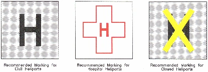
- Markings on runways are white.
- Markings defining the landing area on a heliport are also white except for hospital heliports, which use a red "H" on a white cross.
- Markings for taxiways, areas not intended for aircraft use (such as closed and hazardous areas), and holding positions (even if on a runway) are yellow.
Runway Markings
-
Runways Classification:
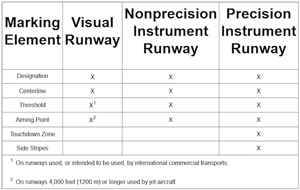
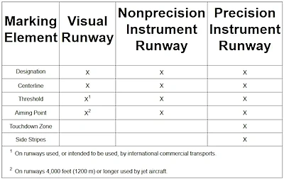
- There are three types of runways, each with an associated level of markings: []
-
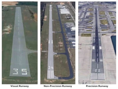
Visual Runways:
- Visual runways are runways without an existing or planned instrument approach procedure.
- Airports mark visual runways with the runway number and a dashed runway centerline. []
- Visual runways may also include threshold markings if intended for international operations.
- Aiming points may be included on runways 4,000' or longer used by jet aircraft.
-
Non-Precision Runways:
- Non-precision runways are those with at least one end that has a non-precision approach procedure.
- Non-precision runways do not incorporate an electric glide slope, and the corresponding runway markings vary accordingly. []
- In many cases, however, non-precision runways will look similar to visual runways.
-
Precision Runways:
- Precision runways are those that have at least one runway with non-visual precision approach aids such as an Instrument Landing System (ILS) or Precision Approach Radar (PAR). []
- These types of runways typically provide some type of glide-slope information, including what is available on the non-precision runway: side stripes, touchdown zone markings, and fixed-distance markings.
-
- There are three types of runways, each with an associated level of markings: []
-
Runway Designators:
- Because wind affects aircraft during takeoff and landing, engineers design runways to align with the local prevailing winds.
- Numbers identify runways, indicating that runway's magnetic heading to the nearest 10° increment of the azimuth of the runway centerline. []
- Example: 084° is marked 8.
- Example: 085° is marked 8 or 9.
- Example: 086° is marked 9.
- Example: 210° is marked 21.
- This number becomes the runway's name and is how Air Traffic Control (ATC) and others refer to it.
- Airports mark the opposite end of the runway with the reciprocal heading.
- Reciprocal heading is determined by adding or subtracting 180° from the runway heading.
- You must therefore add 180 to any runway 180 or below, and subtract 180 to anything 180 or above.
- Example: (using runway 26) 260° - 180° = 080° (runway 8).
- Example: (using runway 8) 080° + 180° = 260° (runway 26).
- If your answer comes out to be greater than 360, or negative, then you added when you should have subtracted, or vice versa.
- Parallel runways are designated by numbers and/or "L," "C," and/or "R," which stand for left, center, and/or right.
- Example: 21L, 21C, and/or 21R.
- When there are only two parallel runways, the "center" is omitted, and only "left" and "right" are used.
- When multiple parallel runways at the same airport are separated by a large distance, such as by a central terminal or several terminals, the runways may be designated as non-parallel runways to avoid pilot confusion.
- Note that wind directions are reported in degrees magnetic to provide an applicable reference to the runway direction.
-
Runway Centerline Marking:
- Runway centerline markings identify the center of the runway for guidance on takeoff and landing. []
- Painted white in color.
- One centerline marking is 120' in length, and the gap between markings is 80', giving 200' for a full set.
-
Runway Aiming Point:
- Aiming point markers serve as a visual target for landing aircraft. []
- Consists of two broad white stripes located on each side of the runway, about 1,000' from the landing threshold.
-
Runway Touchdown Zone Markings:
- Thin white stripes mark the touchdown zone for landing operations and appear at 500-foot (150-meter) intervals. []
- Three, two, and then one thin striped symmetrical bars arranged in pairs on each side of the runway centerline.
- For runways with touchdown zone markings on both ends, airports remove any pairs of markings that extend to within 900 feet (270 meters) of the midpoint between the thresholds.
-
Runway Side Stripe Markings:
- White lines identifying the edges of the runway provide visual contrast between the runway and the abutting terrain or shoulders. []
-
Runway Shoulder Markings:
- Yellow lines may supplement runway side stripes to mark pavement areas beside the runway that aircraft should not use.
-
Runway Threshold Markings:
- Runway threshold markings identify the beginning of the runway that is available for landing and come in two configurations:
- They either consist of eight longitudinal stripes of uniform dimensions disposed symmetrically about the runway centerline, or the number of stripes is related to the runway width. []
- White stripes correspond to the width of the runway:
- 4 stripes = 60' wide.
- 6 stripes = 75' wide.
- 8 stripes = 100' wide.
- 12 stripes = 150' wide.
- 16 stripes = 200' wide.
- In some instances, the landing threshold may be relocated or displaced.
-
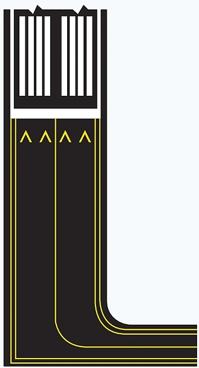
Displaced Threshold:
- A displaced threshold is a threshold located at a point on the runway other than the designated beginning of the runway. []
- Displacement of a threshold is usually the result of obstruction mitigation.
- Displacement of a threshold therefore reduces the length of runway available for landings.
- Pilots may use the portion of the runway behind a displaced threshold for taxi, takeoff, and landing rollout, but not for touchdown.
- Exists usually because of obstructions.
- On runways with a displaced threshold, airports mark the beginning of the landing zone with a 10-foot solid white line.
- White arrows are located along the centerline in the area between the beginning of the runway and the displaced threshold.
- The demarcation bar separates the displaced threshold area from a blast pad, stopway, or taxiway that precedes the runway.
- A displaced threshold is a threshold located at a point on the runway other than the designated beginning of the runway. []
-
Relocated Runway Threshold:
- Due to construction, maintenance, or other activities, a threshold may be closed/moved for varying periods of time.
- When the threshold is relocated, the closed portion of the runway is not available for aircraft takeoff or landing, but it is available for taxiing.
- When airports relocate thresholds, it closes not only a set portion of the approach end of a runway but also shortens the length of the opposite-direction runway.
- Closure will be noted via Notice to Airmen (NOTAM) (for example, 10/28 W 900 CLSD), but the method of marking may vary.
- Methods of identifying the new threshold may vary, with one common practice being to use a white threshold bar 10 feet wide across the runway.
- Although the runway lights in the area between the old threshold and the new threshold will not be illuminated, the runway markings in this area may or may not be obliterated, removed, or covered.
- Yellow arrowheads are placed across the width of the runway just before the threshold bar. []
- Runway threshold markings identify the beginning of the runway that is available for landing and come in two configurations:
-
Demarcation Bar:
- Delineates a runway with a displayed threshold from a blast pad, stop-way, or taxiway that precedes the runway.
- The demarcation bar is 3' (1m) wide and yellow.
-
Chevrons:
- Used to show pavement areas aligned with the runway that are unusable for landing, takeoff, and taxiing.
- Chevrons are yellow.
-
Runway Threshold Bar:
- Runway threshold bars delineate the beginning of the available runway for landing when the threshold has been displayed or relocated.
- A 10' (3M) wide bar extends across the width of the runway.
-
Blast-pad/Stop-way:
- Referred to as an overrun and may be used as such. []
- Cannot be used for normal operation.
- Allows propeller or jet blasts to dissipate safely.
-
Runway Safety Area:
- The runway safety area (RSA) is a defined surface surrounding the runway, prepared or suitable to reduce the risk of airplane damage in the event of an undershoot, overshoot, or excursion from the runway.
- The dimensions of the RSA vary and can be determined using the criteria in AC 150/5300-13, Airport Design, Chapter 3.
- Figure 3-1 in AC 150/5300-13 depicts the RSA.
- Additionally, it provides greater accessibility for firefighting and rescue equipment in emergencies.
- The RSA is typically graded and mowed.
- The presence of the runway holding position signs and markings on the adjoining taxiway stubs usually identifies the lateral boundaries.
- Aircraft should not enter the RSA without making sure of adequate separation from other aircraft during operations at uncontrolled airports.
- The runway safety area (RSA) is a defined surface surrounding the runway, prepared or suitable to reduce the risk of airplane damage in the event of an undershoot, overshoot, or excursion from the runway.


Taxiway Markings
-
Centerline Markings:
- Centerline markings provide a visual cue to permit taxiing along a designated path.
- Ideally, pilots should maintain centerline, but be aware that this does not guarantee wingtip clearance of obstacles on either side.
-
Two Types of Taxiway Centerline Markings:
-
Normal Taxiway Centerline:
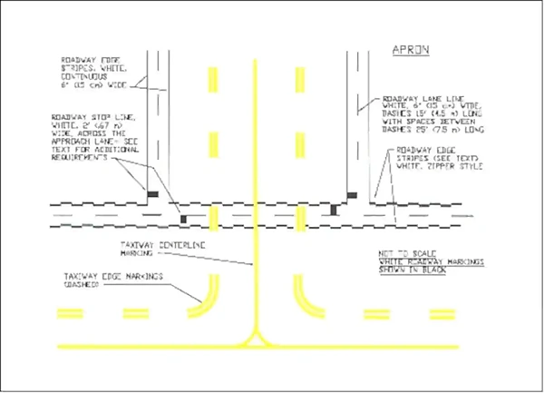
- Normal taxiway centerlines consist of a single continuous yellow line, 6 inches (15 cm) to 12 inches (30 cm) in width. []
-
Enhanced Taxiway Centerline:
- Some airports, mainly larger commercial service airports, use an enhanced taxiway centerline.
- The enhanced taxiway centerline marking consists of a parallel line of yellow dashes on either side of the normal taxiway centerline.
- Airports enhance taxiway centerlines with up to 150 feet of warning before a runway holding position marking, alerting pilots that they are approaching the marking and must prepare to stop unless ATC has cleared them to enter or cross the runway. []
-
- Note that taxiway markings are present on runways to guide pilots off the runway onto a taxiway.
- Taxiway markings are absent at runway intersections to avoid pilots accidentally taxiing off one runway onto another.
-
Taxiway Edge Markings:
- Airports use taxiway edge markings to define the taxiway edge, especially when the pavement and taxiway edges do not align.
-
Two Types of Taxiway Edge Markings:
-
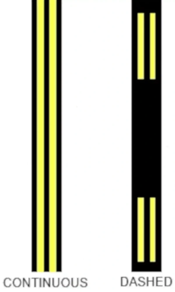
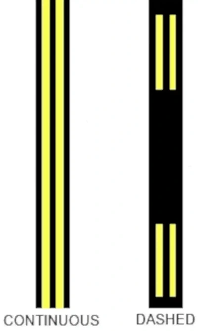
Continuous Markings:
- Consists of a double yellow line, each 6 inches (15cm) in width, separated by 6 inches. []
- These continuous markings delineate areas where aircraft operation is not intended.
-
Dashed Markings:
- These markings are used when there is an operational need to define the edge of a taxiway or taxilane on a paved surface where the adjoining pavement to the taxiway edge is intended for use by aircraft, e.g., an apron.
- Consists of a broken double yellow line, with each line being at least 6 inches (15 cm) in width, spaced 6 inches (15 cm) apart (edge to edge).
- These lines are 15' (4.5m) in length with 25' (7.5m) gaps. []
-
-
Taxi Shoulder Markings:
- Although shoulders may appear to be full-strength pavement, they are not intended for aircraft use and may be unable to support an aircraft.
- In these areas, taxiway shoulder markings indicate that the pavement is unusable.
- Examples: taxiways, holding bays, and aprons are sometimes provided with paved shoulders to prevent blast and water erosion, which are not intended for aircraft use.
- Used where conditions exist, such as islands or taxiway curves, that may confuse as to which side of the edge stripe is for use by aircraft. []
- Consists of yellow lines perpendicular to the taxiway edge markings.
-
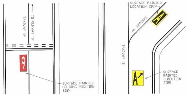
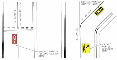
Surface Painted Taxiway Direction Signs:
- Written with a yellow background with black inscription.
- Supplement location signs, located alongside the taxiway, assist the pilot in confirming the taxiway designation on the right side of the centerline.
- These markings are on the right side of the centerline. []
- Turns to the left, being on the left side of the taxiway centerline; right, being on the right side.
-
Surface Painted Location Signs:
- Surface-painted location signs have a black background and yellow inscription.
- Supplement location signs, located alongside the taxiway and assist the pilot in confirming the designation of the taxiway on which the aircraft is located, on the right side of centerline. []
-
Geographic Position Markings:
- Located at points along low-visibility taxi routes designated in the airport's Surface Movement Guidance Control System (SMGCS) plan. []
- Identifies the location of taxiing aircraft when Runway Visual Range (RVR) is below 1200' (360m).
- Positioned to the left of the centerline in the direction of taxi.
- Comprised of a black circle contiguous to a white ring with a pink circle in the middle.
- The FAA reverses the white and black rings on blacktop to improve readability.
- Designated with a number or a number and letter to correspond to the consecutive position of the marking on the route.


Hold Position Markings
-
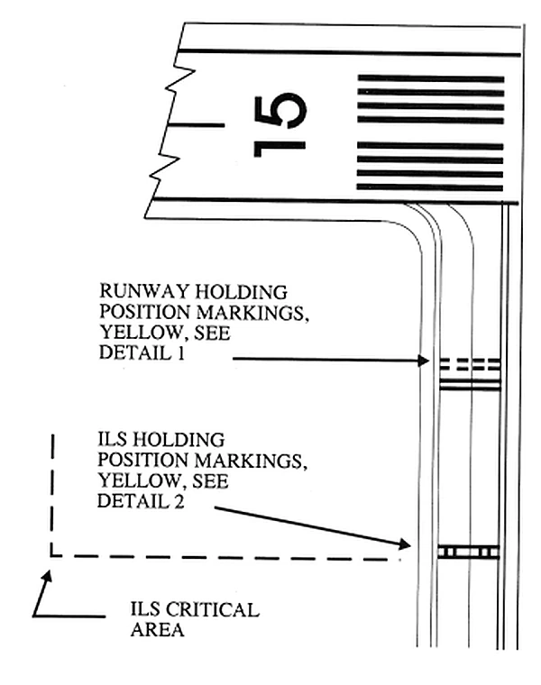
Runway Holding Position Markings:
- Runway hold position signs denote the designation of an intersecting runway.
- On runways, these markings indicate where aircraft MUST STOP as they approach.
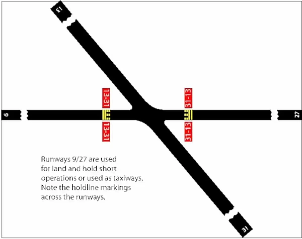
- They may also be placed where a runway intersects a runway for Land and Hold Short operations (LAHSO).
- Generally placed between 125-250' from the runway centerline.
- Consists of four yellow lines, two solid and two dashed, spaced 6 to 12 inches apart, and extending across the width of the taxiway or runway.
- The solid lines are always on the side where the aircraft is to hold.
- There are three locations where runway holding position markings are encountered.
-
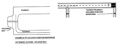
Runway Holding Position Markings on Taxiways:
- These markings indicate points on a taxiway where aircraft must stop if ATC has not issued clearance to enter or cross the runway. [/]
- Generally, runway holding position markings also identify the boundary of the runway safety area (RSA) for aircraft exiting the runway.
- When instructed by ATC, "Hold short of [Runway]," the pilot MUST STOP so that no part of the aircraft extends beyond the runway holding position marking.
- ATC will state "Cleared to cross [Runway]" when approved to proceed beyond the hold line.
- When approaching runways at airports with an operating control tower, pilots must not cross the runway holding position marking without ATC clearance.
- Pilots approaching runways at airports without an operating control tower must ensure adequate separation from other aircraft, vehicles, and pedestrians before crossing the holding position markings.
- An aircraft exiting a runway is not clear of the runway until all parts of the aircraft have crossed the applicable holding position marking.
-
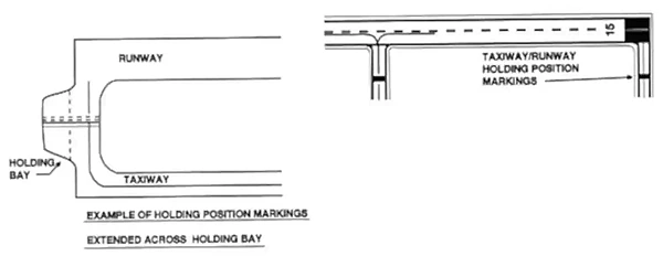
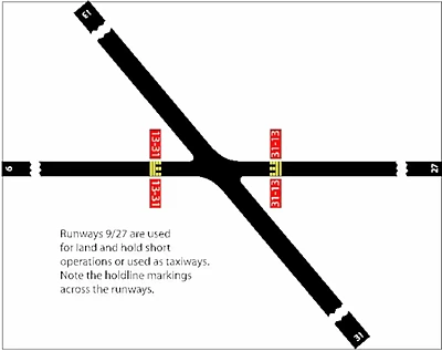
Runway Holding Position Markings on Runways:
- These markings identify the locations on runways where aircraft MUST STOP.
- These markings are located on runways used by ATC for Land and Hold Short Operations and Taxiing operations.
- For taxiing operations, the pilot MUST STOP before the holding position markings unless ATC explicitly authorizes crossing.
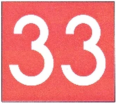
- A sign with a white inscription on a red background is located adjacent to these holding position markings. []
- The holding position markings are placed on runways prior to the intersection with another runway, or some designated point.
- Pilots receiving instructions "cleared to land, [Runway]" from ATC are authorized to use the entire landing length of the runway and should disregard any holding position markings located on the runway.
- Pilots receiving and accepting instructions "cleared to land [Runway], hold short of [Runway]" from ATC must either exit [Runway] or stop at the holding position before.
- Otherwise, pilots are authorized to use the entire landing length of the runway and disregard the holding position markings.
-
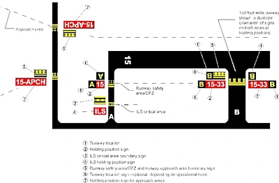
Holding Position Markings on Taxiways Located in Runway Approach Areas:
- These markings are used at some airports where it is necessary to hold an aircraft on a taxiway in the approach or departure area of a runway to prevent it from interfering with runway operations. []
- This marking is collocated with the holding position sign for the runway approach area.
- When specifically instructed by ATC "Hold short of [Runway Approach Area]," the pilot MUST STOP so that no part of the aircraft extends beyond the holding position marking.
-
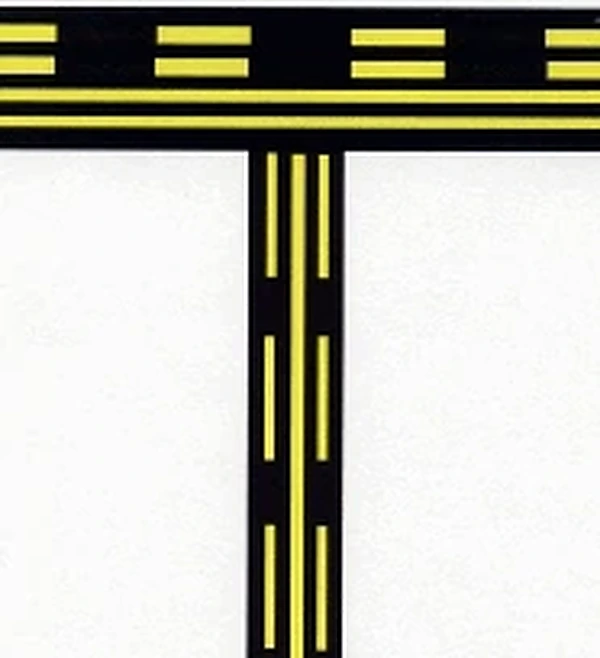
Holding Position Markings for Instrument Landing System (ILS):
- At airports equipped with an ILS, they may move the hold line back or create an ILS hold line for that type of operation.
- Holding position markings for ILS critical areas consist of two yellow solid lines spaced two feet apart, connected by pairs of solid lines spaced ten feet apart, extending across the width of the taxiway as shown. []
- A sign with white text on a red background is located adjacent to these hold position markings. []
- When instructed by ATC to hold short of the ILS critical area, pilots MUST STOP so that no part of the aircraft extends beyond the holding position marking.
- When approaching the holding position marking, pilots must not cross the marking without ATC clearance.
- The ILS critical area is not clear until all parts of the aircraft have crossed the applicable holding position marking.
-
Holding Position Markings for Intersecting Taxiways:
- Holding position markings for taxiway/taxiway intersections consist of a single dashed line extending across the width of the taxiway. []
- They are located on taxiways where ATC holds aircraft short of a taxiway intersection.
- When instructed by ATC "hold short of [Taxiway]," the pilot MUST STOP so that no part of the aircraft extends beyond the holding position marking.
- When the marking is not present, the pilot MUST STOP the aircraft at a point which provides adequate clearance from an aircraft on the intersecting taxiway.
-
Surface Painted Holding Position Signs:
- Surface-painted holding position signs have a red background with white inscription and supplement the signs at the holding position.
- This type of marking is normally used where the width of the holding position on the taxiway is greater than 200' (60m).
- It is located on the left side of the taxiway centerline, on the holding side, before the holding position marking. []


Other Markings
-
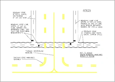
Vehicle Roadway Markings:
- Used when necessary to define a pathway for vehicle operations on or crossing areas that are also intended for aircraft.
- Markings consist of a white solid line to delineate each edge of the roadway and a dashed line to separate lanes within the edges of the roadway.
- In lieu of the solid lines, zipper markings may be used to delineate the edges of the vehicle roadway. [/]
-
Very-High Omni-Directional Range (VOR) Receiver Checkpoint Markings:
- The VOR receiver checkpoint marking allows the pilot to check aircraft instruments with navigational aid signals.
- Consists of a painted circle with an arrow in the middle; the arrow is aligned in the direction of the checkpoint azimuth.
- This marking, and an associated sign, is located on the airport apron or taxiway at a point selected for easy access by aircraft but where other airport traffic is not to be unduly obstructed. []
- The associated sign contains the VOR station identification letter and course selected (published) for the check, the words "VOR check course," and Distance Measuring Equipment (DME) data (when applicable) using black numerals on a yellow background.
- The letters and numerals are black on a yellow background.
- These locations on the airfield and information about them can be found in the Chart Supplement U.S..
- Example:
- DCA 176-356
VOR check course
DME XXX.
- DCA 176-356
-
Non-movement Area Boundary Markings:
- These markings delineate the movement area, i.e., area under ATC.
- These markings are yellow and located on the boundary between the movement and non-movement area.
- The non-movement area boundary markings consist of two yellow lines (one solid and one dashed) 6 inches (15cm) in width.
- The solid line is located on the non-movement area side, while the dashed yellow line is located on the movement area side. []
-

Non-movement Area Boundary Markings
-
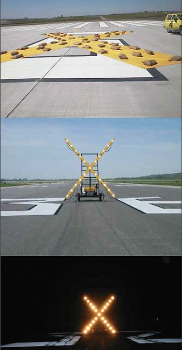
Marking and Lighting of Permanently Closed Runways and Taxiways:
- For permanently closed runways and taxiways, airports disconnect lighting circuits.
- Airports remove the runway threshold, runway designation, and touchdown markings, and yellow crosses are placed at each end of the runway and at 1,000' intervals.
-
Temporarily Closed Runways and Taxiways:
- To provide a visual indication to pilots that a runway is temporarily closed, yellow "Xs" are placed on the runway only at each end of the runway. []
- A raised lighted yellow cross may be placed on each runway end in place of permanent markings to indicate the runway is closed.
- A visual indication may not be present depending on the reason for the closure, the closure duration, the airfield configuration, and the existence and hours of operation of an airport traffic control tower.
- Pilots should check NOTAMs and the Automated Terminal Information System (ATIS) for local runway and taxiway closure information.
- Temporarily closed taxiways are usually treated as hazardous areas, in which no part of an aircraft may enter, and are blocked with barricades.
- Alternatively, a yellow cross may be installed at each taxiway entrance.
- Depending on the reason for the closure, duration of closure, airfield configuration, and the existence and the hours of operation of an ATC tower, a visual indication may not be present.
- You must always check NOTAMs and ATIS for runway and taxiway closure information.
- Air traffic control towers are not permitted to issue a taxi clearance for a closed runway.
- To provide a visual indication to pilots that a runway is temporarily closed, yellow "Xs" are placed on the runway only at each end of the runway. []
-
Special Purpose Areas:
- Closed or overrun stopway areas are special-purpose areas.
- Any surface or area which appears usable, but which, due to the nature of its structure, is unusable.
- See EMAS below.
-
Short Takeoff and Landing:
- Short takeoff and landing (STOL) runways will have STOL painted on the approach end.
-
Helicopter Landing Areas:
- Used to identify the landing and takeoff area at a public use heliport and a hospital heliport. []
- The letter "H" in the markings is oriented to align with the intended direction of approach.
-
Helicopter Landing Areas


Airport Signs
- There are six types of signs installed on airfields:
- Mandatory instruction signs, location signs, direction signs, destination signs, information signs, and runway distance remaining signs.
-
Mandatory Instruction Signs:
- Mandatory signs have a red background with a white inscription, used to denote an entrance to a runway or critical area, or an area where an aircraft is prohibited from entering.
- Note that holding position signs provide the pilot with a visual cue as to the location of the holding position marking.
-
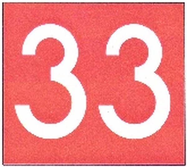
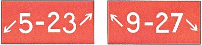
Runway Holding Position Sign:
- This sign is located at the holding position on taxiways that intersect a runway or on runways that intersect other runways and contains the designation of the intersecting runway. []
- Runway numbers are arranged to correspond to the respective runway threshold.
- Example: "15-33" indicates that the threshold for Runway 15 is to the left and the threshold for Runway 33 is to the right.
- On taxiways that intersect the beginning of the takeoff runway, only the designation of the takeoff runway may appear on the sign. []
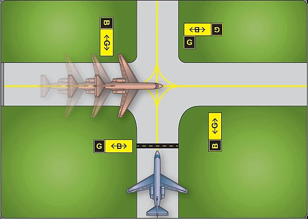
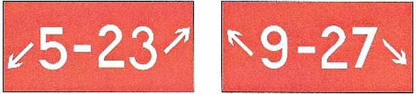
- If the sign is located on a taxiway that intersects the intersection of two runways, the designations for both runways will be shown on the sign along with arrows showing the approximate alignment of each runway. []
- In addition to showing the approximate runway alignment, the arrow indicates the direction to the threshold of the runway whose designation is immediately next to the arrow.
- A runway holding position sign on a taxiway will be installed adjacent to holding position markings on the taxiway pavement.
- On runways, holding position markings will be located only on the runway pavement adjacent to the sign, if the runway is normally used by air traffic control for "Land, Hold Short" operations or as a taxiway.
-
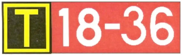
Runway Approach Area Holding Position Sign:
- At some airports, it is necessary to hold an aircraft on a taxiway located in the approach or departure area for a runway so that the aircraft does not interfere with operations on that runway. []
- A sign with the runway designation(s) and the protected area(s) will be located at applicable holding positions on the taxiway.
- For locations protecting only the approach area, the holding position on the taxiway includes a sign identifying the approach end runway designation (e.g., 15) followed by a dash (-) and the letters "APCH."
- For locations protecting both the approach and departure areas, the holding position on the taxiway includes a sign with the approach end runway designation and letters "APCH" followed by a dash (-), the departure end runway designation and the letters "DEP."
- The arrangement of the runway designations and protected areas legend on the sign reflects the orientation of the runway as viewed from the holding position. Holding position markings in accordance with Holding Position Markings, are co−located on the taxiway pavement in line with the sign.
-
ILS Critical Area Holding Position Sign:
- At some airports, when the instrument landing system is being used, it is necessary to hold an aircraft on a taxiway at a location other than the holding position.
- In these situations, the holding position sign for these operations will have the inscription "ILS" and be located adjacent to the holding position marking on the taxiway. []
-
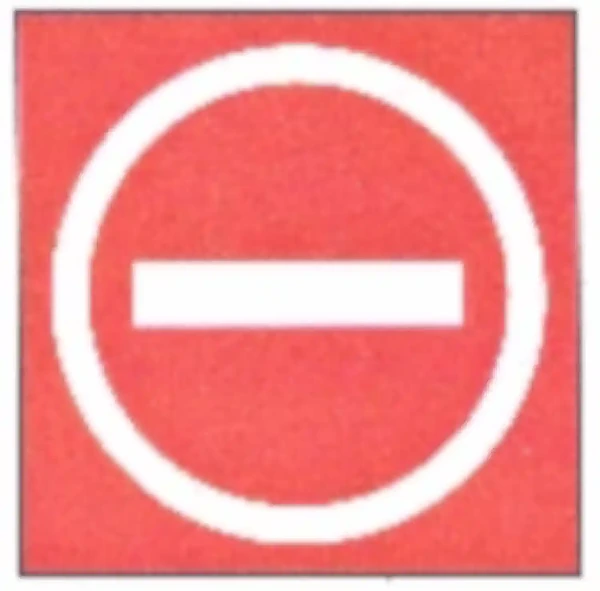
No Entry Sign:
- No entry signs prohibit aircraft from entering areas on taxiways intended for one-way use or at intersections where vehicle roadways might be mistaken for taxiways or other aircraft movement surfaces. []
-
Location Signs:
- Identify either the taxiway or runway where your aircraft is located.
- Other location signs provide a visual cue to pilots to assist them in determining when they are entering/exiting an area.
-
Taxiway Location Sign:
- Has a black background with a yellow inscription and yellow border. []
- The inscription designates the taxiway on which the aircraft is located.
- These signs are installed along taxiways, either alone or in conjunction with direction signs or runway holding position signs. [/]
-
Runway Location Sign:
- Utilizes a black background with a yellow inscription and yellow border. []
- The inscription designates the runway on which the aircraft is located.
- These signs supplement the information pilots obtain from their magnetic compass and are typically installed where two or more nearby runways could cause confusion about which runway the aircraft is on.
-
Runway Boundary Sign:
- The sign has a yellow background with a black inscription with a graphic depicting the pavement holding position marking. []
- This sign, which faces the runway and is visible to the pilot exiting the runway, is located adjacent to the holding position marking on the pavement.
- The sign is intended to provide pilots with another visual cue which they can use as a guide in deciding when they are "clear of the runway."
-
ILS Critical Area Boundary Sign:
- The sign has a yellow background with a black inscription with a graphic depicting the ILS pavement holding position marking. []
- The sign is located adjacent to the ILS holding position marking on the pavement and can be seen by pilots leaving the critical area.
- The sign is intended to provide pilots with a visual cue to ensure "clear of the ILS critical area."
- Aircraft and vehicle access to the ILS critical area must be controlled (by ATC) to ensure the integrity of ILS course signals whenever the official weather observation is a ceiling of less than 800 feet or visibility less than 2 miles.
- It is advisable at non-towered locations to observe the same restriction.
-
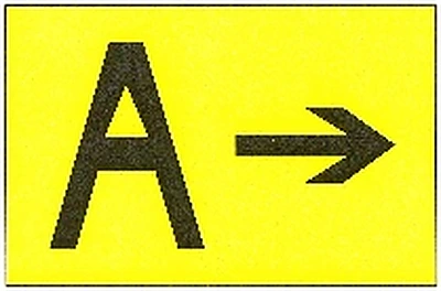
Direction Signs:
- Direction signs have a yellow background with a black inscription.
- The inscription identifies the designation(s) of the intersecting taxiway(s) leading out of the intersection that a pilot would normally be expected to turn onto or hold short of.
- Each designation is accompanied by an arrow indicating the direction of the turn.
- When more than one taxiway designation is shown on the sign each designation and its associated arrow is separated from the other taxiway designations by either a vertical message divider or a taxiway location sign. []
- Direction signs are normally located on the left before the intersection.
- When used on a runway to indicate an exit, the sign is located on the same side of the runway as the exit. []
- The taxiway designations and their associated arrows on the sign are arranged clockwise, starting from the first taxiway on the pilot's left. []
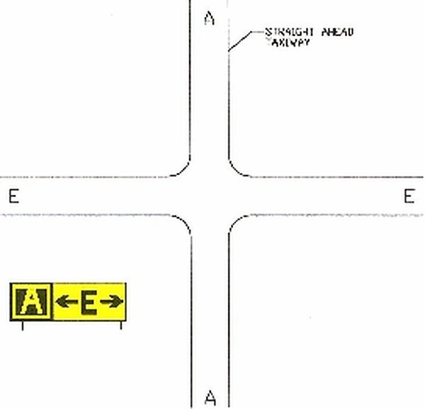
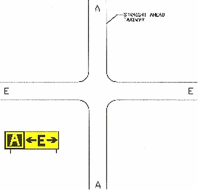
- If a location sign is located with the direction signs, it is placed so that the designations for all turns to the left will be to the left of the location sign; the designations for continuing straight ahead or for all turns to the right would be located to the right of the location sign.
- When only one taxiway crosses an intersection, the sign may display two arrows for that crossing taxiway. [/]
- In this case, the location sign is located to the left of the direction sign.
-
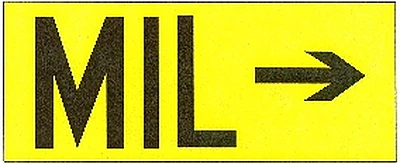
Destination Signs:
- Destination signs also have a yellow background with a black inscription indicating a destination at the airport.
- These signs always have an arrow showing the direction of the taxiing route to that destination.
- When the arrow on the destination sign indicates a turn, the sign is located prior to the intersection.
- Destinations commonly shown on these types of signs include runways, aprons, terminals, military areas, civil aviation areas, cargo areas, international areas, and fixed base operators. []
- An abbreviation may be used as the inscription on the sign for some of these destinations.
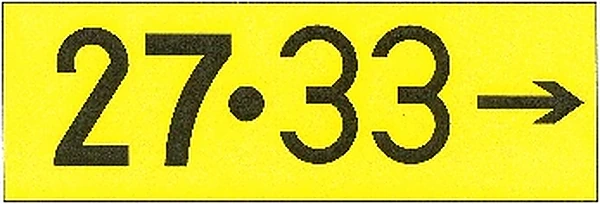
- When a sign lists two or more destinations that share a common taxi route, a "dot" (·) separates the destinations, and a single arrow indicates the direction. []
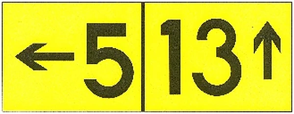
- When the inscription on a sign lists two or more destinations with different taxiing routes, each destination will be accompanied by an arrow and separated from the others on the sign by a vertical black message divider. []
-
Information Signs:
- Information signs have a yellow background with a black inscription.
- Advise pilots on areas not visible from the control tower, applicable radio frequencies, and procedures.
- The airport operator determines the need, size, and location for these signs.
-
Runway Distance Remaining Signs:
- Runway distance remaining signs have a black background with a white numeral inscription and may be installed along one or both sides of the runway. []
- The number on the signs indicates the distance (in thousands of feet) of landing runway remaining.
- The last sign (i.e., the sign with the numeral "1") will be located at least 950 feet from the runway end.


Use of Runway Halfway Signs at Unimproved Airports
- When installed, runway halfway signs provide the pilot with a reference point to judge takeoff acceleration trends.
- Assuming that the runway length is appropriate for takeoff (considering runway condition and slope, elevation, aircraft weight, wind, and temperature), typical takeoff acceleration should allow the airplane to reach 70% of liftoff airspeed by the midpoint of the runway.
- The "rule of thumb" is that if the airplane's acceleration does not allow the airspeed to reach this value by the midpoint, the pilot should abort the takeoff, as it may not be possible to lift off on the remaining runway.
"Rule of Thumb" Considerations:
- Airspeed indicators in small airplanes are not required to be evaluated at speeds below stalling, and may not be usable at 70% of liftoff airspeed.
- Based on a uniform surface condition.
- Puddles, soft spots, areas of tall and/or wet grass, loose gravel, upslope, winds, etc., may impede acceleration or even cause deceleration.
- Even if the airplane reaches 70% of liftoff airspeed by the midpoint, the condition of the remaining runway may not allow further acceleration.
- Pilots should inspect the entire length of the runway before takeoff to ensure the surface is usable.
- Applies only to the runway required for actual liftoff.
- If obstacles affect the takeoff climb path, an appropriate distance must be available after liftoff to accelerate to the best angle-of-climb speed and clear the obstacles.
- This will, in effect, require the airplane to accelerate to a higher speed by the midpoint, particularly if the obstacles are close to the end of the runway.
- In addition, this technique does not account for the effects of upslope or tailwind conditions on takeoff performance.
- These factors will also require greater acceleration than normal and, under some circumstances, prevent takeoff entirely.
- Use of this "rule of thumb" does not alleviate the pilot's responsibility to comply with applicable Federal Aviation Regulations, the limitations and performance data provided in the FAA-approved Airplane Flight Manual (AFM), or, in the absence of an FAA-approved AFM, other data provided by the aircraft manufacturer.
- In addition to their use during takeoff, runway halfway signs provide the pilot with increased awareness of their position along the runway during landing operations.
- Note that there is no standardized symbology for a runway halfway sign. []


Arresting Systems
- Particular military aircraft, when properly equipped, can be rapidly brought to a stop on a runway using cables supported by rubber donuts.
- Solid yellow circles (10' diameter) 30' on center show the location of cables.
- Engineers construct engineered materials arresting systems (EMAS) from high-energy-absorbing materials.
- Crush under the weight of commercial aircraft to slow them.
- More can be found on the aircraft arresting systems page.
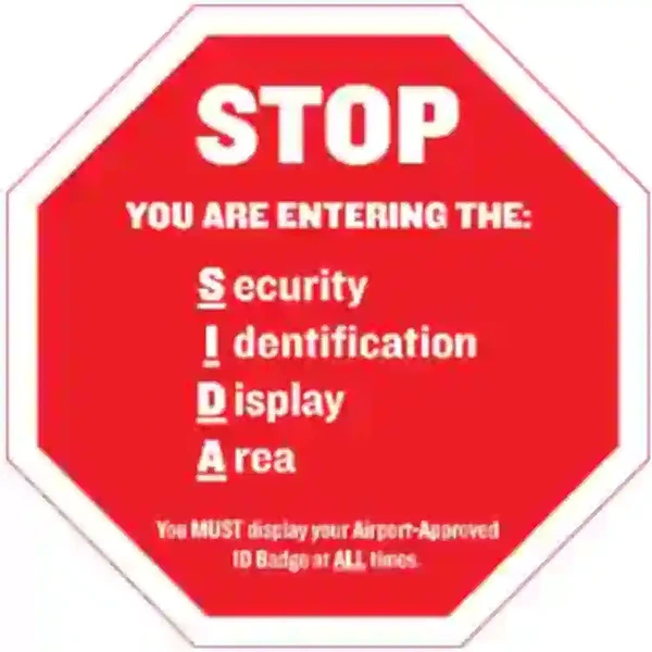
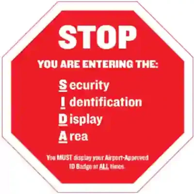
Security Identification Display Areas
- Security Identification Display Areas, or SIDAs, are limited-access areas that require a badge issued in accordance with procedures in CFR 49 Part 1542. []
- A SIDA can include the Air Operations Area (AOA), e.g., aircraft movement area or parking area, or a Secured Area, such as where commercial passengers enplane.
- The AOA may not be a SIDA, but a Secured Area is always a SIDA.
- Individuals may not move through or enter a SIDA unless they are authorized and display proper identification.
- If you are unsure of the location of a SIDA, contact the airport authority for additional information.
- Airports that have a SIDA will have a description and a map detailing the boundaries and pertinent features.
- Authorities may report pilots or passengers who enter a SIDA without proper identification to the Transportation Security Administration (TSA) or airport security, and officials may subject them to civil or criminal fines and prosecution.
- Pilots must brief passengers accordingly.
- Report suspicious activity to the TSA by calling AOPA's Airport Watch Program, 866-427-3287.
- 49 CFR 1540 requires each individual who holds an airman certificate, medical certificate, authorization, or license issued by the FAA to present it for inspection upon a request from TSA.
Use of Runway Declared Distances
- Airport owners are responsible for leading local efforts to manage aviation noise.
- Accordingly, they may propose specific noise abatement plans to the FAA.
- If approved, these plans are implemented through Formal or Informal Runway Use Programs for noise abatement purposes.
- ATC will assign the runway/s most nearly aligned with the wind when 5 knots or more, or the "calm wind" runway when less than 5 knots, unless:
- Use of another runway is operationally advantageous.
- A Runway Use Program is in effect.
- Note: Tailwind and crosswind considerations take precedence over delay/capacity considerations and noise abatement operations/procedures.
- ATC will assign the runway/s most nearly aligned with the wind when 5 knots or more, or the "calm wind" runway when less than 5 knots, unless:
- If a pilot prefers to use a runway other than the one specified, the pilot must advise ATC. ATC may honor such requests as soon as is operationally practicable.
- ATC will advise pilots when the requested runway is noise sensitive.
- When use of a runway other than the assigned one is requested, pilot cooperation is encouraged to prevent disruption of traffic flows or the creation of conflicting patterns.
-
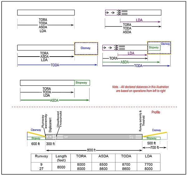
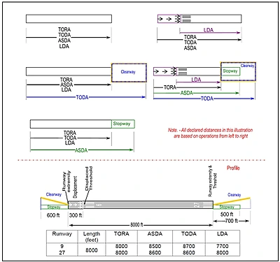
Declared Distances:
- Declared distances for a runway represent the maximum distances available and suitable for meeting takeoff and landing distance performance requirements. [/]
- FAA runway design standards determine this distance by adding to the physical length of the paved runway any clearway or stopway and subtracting from that sum any lengths necessary to obtain the standard runway safety areas, runway object-free areas, or runway protection zones.
- As a result of these additions and subtractions, the declared distances for a runway may be more or less than the physical length of the runway as depicted on aeronautical charts and related publications, or available in electronic navigation databases provided by either the U.S. Government or commercial companies.
- All 14 CFR Part 139 airports report declared distances for each runway. Other airports may also report declared distances for a runway if necessary to meet runway design standards or to indicate the presence of a clearway or stopway. Where reported, declared distances for each runway end are published in the Chart Supplement U.S. For runways without published declared distances, the declared distances may be assumed to be equal to the physical length of the runway unless there is a displaced landing threshold, in which case the Landing Distance Available (LDA) is shortened by the amount of the threshold displacement.
- A "D" symbol is shown on U.S. Government charts to indicate that runway declared distance information is available (See appropriate Chart Supplement U.S., Alaska, or Pacific).
- The FAA uses the following definitions for runway declared distances:
-
Takeoff Run Available (TORA):
- The runway length declared available and suitable for the ground run of an airplane taking off.
- The TORA is typically the physical length of the runway, but it may be shorter than the runway length if necessary to satisfy runway design standards.
- For example, the TORA may be shorter than the runway length if a portion of the runway must be used to satisfy runway protection zone requirements.
- The runway length declared available and suitable for the ground run of an airplane taking off.
-
Takeoff Distance Available (TODA):
- The takeoff run available plus the length of any remaining runway or clearway beyond the far end of the takeoff run available.
- The TODA is the distance declared available for satisfying takeoff distance requirements for airplanes, where the certification and operating rules, and available performance data, allow for the consideration of a clearway in takeoff performance computations.
- The length of any available clearway will be included in the TODA published in the entry for that runway end within the Chart Supplement U.S.
- The takeoff run available plus the length of any remaining runway or clearway beyond the far end of the takeoff run available.
-
Accelerate-Stop Distance Available (ASDA):
- The runway plus stopway length declared available and suitable for the acceleration and deceleration of an airplane aborting a takeoff.
- The ASDA may be longer than the physical length of the runway when a stopway has been designated available by the airport operator, or it may be shorter than the physical length of the runway if necessary to use a portion of the runway to satisfy runway design standards; for example, where the airport operator uses a portion of the runway to achieve the runway safety area requirement.
- ASDA is the distance used to satisfy the airplane accelerate-stop distance performance requirements, where the certification and operating rules require accelerate-stop distance computations.
- The Chart Supplement U.S. entry for each runway end includes the length of any available stopway in the published ASDA.
- The runway plus stopway length declared available and suitable for the acceleration and deceleration of an airplane aborting a takeoff.
-
Landing Distance Available (LDA):
- The runway length declared available and suitable for a landing airplane.
- The LDA may be less than the physical length of the runway, or the length of the runway remaining beyond a displaced threshold, if necessary to satisfy runway design standards; for example, where the airport operator uses a portion of the runway to meet the runway safety area requirement.
- Although some runway elements (such as stopway length and clearway length) may be available information, pilots must use the declared distances determined by the airport operator and not attempt to independently calculate declared distances by adding those elements to the reported physical length of the runway.
- The runway length declared available and suitable for a landing airplane.
-
- The airplane operating rules and/or the airplane operating limitations establish minimum takeoff and landing distance requirements. Manufacturers base these figures on performance data provided in the Airplane Flight Manual or Pilot's Operating Handbook.
- The minimum distances required for takeoff and landing, obtained either during planning before takeoff or during performance assessments conducted at the time of landing, must fall within the applicable declared distances before the pilot can accept that runway for takeoff or landing.
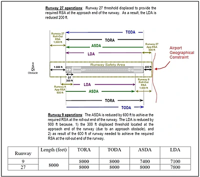
- Runway design standards may impose restrictions on the amount of runway available for use in takeoff and landing that are not apparent from the reported physical length of the runway or from runway markings and lighting.
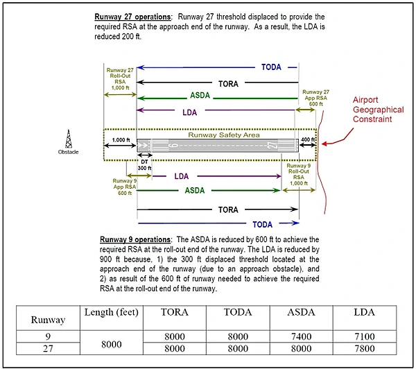
- The runway elements of Runway Safety Area (RSA), Runway Object Free Area (ROFA), and Runway Protection Zone (RPZ) may reduce a runway's declared distances to less than the physical length of the runway at geographically constrained airports.
- When calculating takeoff or landing performance, pilots must use the declared distances published for a runway rather than its physical length.
- While some runway elements associated with declared distances may be identifiable through runway markings or lighting (for example, a displaced threshold or a stopway), the individual declared distance limits are not marked or otherwise identified on the runway.
- An aircraft may operate beyond a declared distance limit during the takeoff, landing, or taxi operation, provided proper marking of the runway surface as usable runway.
- EXAMPLE:
- The declared LDA for runway "9" must be used when demonstrating compliance with the landing distance requirements of the applicable airplane operating rules and/or airplane operating limitations, or when performing a before-landing performance assessment. The LDA is less than the physical runway length, not only because of the displaced threshold, but also because of the subtractions necessary to meet the RSA beyond the far end of the runway. However, during the actual landing operation, it is permissible for the airplane to roll beyond the unmarked end of the LDA.
- The declared ASDA for runway "9" must be used when demonstrating compliance with the accelerate-stop distance requirements of the applicable airplane operating rules and/or airplane operating limitations. The ASDA is less than the physical length of the runway due to the subtractions necessary to achieve the full RSA requirement. However, in the event of an aborted takeoff, it is permissible for the airplane to roll beyond the unmarked end of the ASDA as the aircraft comes to a full stop on the remaining usable runway.
- Declared distances for a runway represent the maximum distances available and suitable for meeting takeoff and landing distance performance requirements. [/]
Airport Markings & Signs Knowledge Check
Private Pilot

Core Knowledge Review
Review the foundational knowledge, key concepts, and practical considerations for Airport Markings & Signs.
Foundational
Immediate Feedback
Answer Explanations
Commercial Pilot

Advanced Application
Apply your knowledge of Airport Markings & Signs to advanced operational scenarios, risk management, and aeronautical decision-making.
Advanced
Scenario Based
Risk Management
Why Take a Quiz?
Quizzes reinforce key concepts, identify knowledge gaps, and build confidence for real-world decisions in the cockpit.
Airport Markings & Signs Interactive Scenario
Interactive Scenario
Loading scenario details...
Decision 1
0%
Scenario Complete
Airport Markings & Signs Conclusion
- It is essential to understand the meanings of the signs, markings, and lights used at airports as surface navigational aids.
- Pilots should report ineffective, incorrect, or confusing markings in at least one of three ways:
- To the airport operator;
- To the FAA regional airport division, and/or;
- Entered into the Aviation Safety Reporting Program.
- All taxiways should have centerline markings and runway holding position markings whenever they intersect a runway.
- Airports use taxiway edge markings to separate the taxiway from pavement not intended for aircraft use or to delineate the taxiway's edge clearly.
- Taxiways may also have shoulder markings and holding position markings for Instrument Landing System (ILS) critical areas, as well as taxiway/taxiway intersection markings.
- Additional resources are available through tools such as the FAA's Runway Safety Simulator.
- Want to test your knowledge? Consider the following quiz:
- Be mindful of markings and signs obscured by snow, rubber buildup, and other debris.
- To learn more about airport rubber removal, see: Why 10,000 pounds of rubber are stripped from runways.
-
Wrong Surface Landings/Takeoffs:
- Familiarize pilots with Chart Supplements, Airport Diagrams, NOTAMs, and other preflight resources.
- Use the FAA's From the Flight Deck videos! www.faa.gov/airports/runway_safety/videos/.
- Share techniques to verify correct runway alignment, like magnetic compass orientation, referencing underlying instrument approach courses, mnemonic devices, etc.
- Electronic Flight Bags and moving map displays should increase pilot situational awareness and safety.
- Do not become overly reliant on technology as a compensating skill or a distraction.
- Encourage runway safety checks on short final, including verifying the correct runway and ensuring there are no vehicles or aircraft present.
- Strictly enforce a go-around policy when there is any doubt about making a safe landing on the correct surface.
- For more information or resources, check out SAFO 17010.
- Familiarize pilots with Chart Supplements, Airport Diagrams, NOTAMs, and other preflight resources.
- Still looking for something? Continue searching:

Airport Markings & Signs References
- AOPA - Runway Safety Flashcards.
- Federal Aviation Administration - Pilot/Controller Glossary.
- Advisory Circular (150/5340-1) Standards for Airport Markings.
- Advisory Circular (150/5390-2D) Heliport Design.
- Advisory Circular (150/5300-13) Airport Design.
- Advisory Circular (150/5345-44) Specification for Runway and Taxiway Signs.
- Advisory Circular (150/5340-18) Standards for Airport Sign Systems.
- Aeronautical Information Manual (2-3-1) General.
- Aeronautical Information Manual (2-3-2) Airport Pavement Markings.
- Aeronautical Information Manual (2-3-3) Runway Markings.
- Aeronautical Information Manual (2-3-4) Taxiway Markings.
- Aeronautical Information Manual (2-3-5) Holding Position Markings.
- Aeronautical Information Manual (2-3-6) Other Markings.
- Aeronautical Information Manual (2-3-7) Airport Signs.
- Aeronautical Information Manual (2-3-8) Mandatory Instruction Signs.
- Aeronautical Information Manual (2-3-9) Location Signs.
- Aeronautical Information Manual (2-3-10) Direction Signs.
- Aeronautical Information Manual (2-3-11) Destination Signs.
- Aeronautical Information Manual (2-3-12) Information Signs.
- Aeronautical Information Manual (2-3-13) Runway Distance Remaining Signs.
- Aeronautical Information Manual (2-3-14) Aircraft Arresting Systems.
- Aeronautical Information Manual (2-3-15) Security Identifications Display Area (Airport Ramp Area).
- Aeronautical Information Manual (4-3-6) Use of Runways/Declared Distances.
- Aeronautical Information Manual (4-3-20) Exiting the Runway After Landing.
- Aeronautical Information Manual (7-6-8) Use of Runway Half-way Signs at Unimproved Airports.
- AOPA Air Safety Institute - Runway Safety Flashcards.
- AOPA - Safety Quiz: Airport Signs and Markings.
- AOPA - Runway Markings.
- Bold Method - ILS Critical Area: When Should You Hold Short?.
- JO 7110.65Z (3-7-5) Precision Approach Critical Area.
- FAA InFO (12007) Instrument Landing System (ILS) Fluctuations Caused by Movement through the ILS Critical Area.
- International Civil Aviation Organization (ICAO).
- Gizmodo - A beginner's Guide to the Secret Language of Airport Runways.
- Federal Aviation Administration - Pilots' Guide to Airport Signs and Markings.