Visual Glide Slope Indicators
Visual Glide Slope Indicators provide aid pilots in landing through the use of lighted or other visual glide slope indications.
Introduction to Visual Glide Slope Indicators
- Visual Glide Slope Indicators provide descent guidance [Figure 1-3]
- The Visual Approach Slope Indicator (VASI) is the most common visual glidepath systems in use today
- Closely following the VASI in popularity is the Precision Approach Path Indicator which functions much in the same way as a VASI
- Other systems that are significantly less common that you may see are Tri-Color Systems, Pulsating Systems, and Alignment of Elements Systems.
- A system referred to as the Stand-Alone Final Approach Runway Occupancy Signal also exists not as a means of visual glide slope indication, but as a safety feature as to the status of the runway
Visual Glide Slope Indicators Key Highlights
- Visual glide slope indicators provide pilots with visual descent guidance during approach and landing operations.
- Common visual glide slope systems include VASI, PAPI, tri-color, and pulsating visual approach slope indicators.
- Visual glide slope indicators help pilots maintain a stabilized approach path to the runway touchdown zone.
- VASI and PAPI systems use combinations of red and white lights to indicate whether the aircraft is above, below, or on glidepath.
- Maintaining the proper glidepath improves obstacle clearance, runway alignment, and landing consistency.
- Visual glide slope systems are typically aligned to provide safe obstacle clearance for standard aircraft operations.
- Approach slope indications may not provide adequate clearance for all aircraft types or unusual approach configurations.
- Environmental conditions such as haze, precipitation, and bright sunlight can affect visibility of glide slope lighting systems.
- Pilots should cross-check visual glide slope indications with runway environment cues and instrument information when available.
- Understanding visual glide slope indicators improves approach stability, situational awareness, and overall landing safety.
Visual Approach Slope Indicator
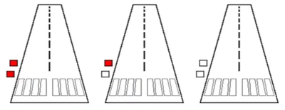
- The Visual Approach Slope Indicator, or VASI, is a system of lights so arranged to provide visual descent guidance information during the approach to a runway
- The principle is color differentiation between the white and red lamps
- Each light unit projects a beam of light having a white segment in the upper part of the beam and red segment in the lower part of the beam
- The light units are arranged so that the pilot using the VASIs during an approach will see the combination of lights [//]
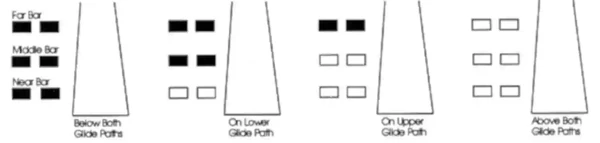
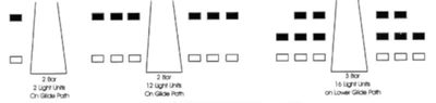
- Consists of either 2, 4, 6, 12, or 16 light units arranged in bars referred to as near, middle, and far bars
- Most VASI installations consist of 2 bars, near and far, and may consist of 2, 4, or 12 light units
- Some VASIs consist of three bars, near, middle, and far, which provide an additional visual glide path to accommodate high cockpit aircraft
- This installation may consist of either 6 or 16 light units
- VASI installations consisting of 2, 4, or 6 light units are located on one side of the runway, usually the left
- Where the installation consists of 12 or 16 light units, the units are located on both sides of the runway
- Visible 3-5 miles during the day and up to 20 or more at night
-
Visual Approach Slope Indicator Lateral Guidance:
- Lateral course guidance is generally provided by the runway or runway lights.
-
Visual Approach Slope Indicator Vertical Guidance:
- The VASI consists of light units arranged in bars
- There are two-bar and three-bar VASIs:
- Two bar VASI consists of a near and far light which provides a single glideslope, typically 3°
- Three bar VASI consists of near, middle and far light bars which provide two glideslopes
- Lower provided by the near and middle bar usually provides a 3° glide slope
- Upper provided by the middle and far bars typically set 1/4° higher for high cockpit aircraft to provide safe threshold crossing heights
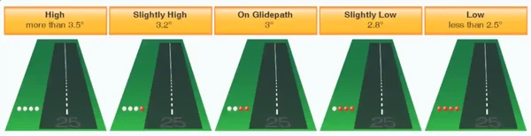
- Although normal glide path angles are 3°, angles at some locations may be as high as 4.5° for obstacle clearance
- Pilots of high performance aircraft are cautioned that use of VASI angles in excess of 3.5 degrees may cause an increase in runway length required for landing and rollout
- In addition to the runway however, VASI's provide safe obstruction clearance within plus or minus 10° of the extended runway centerline and to 4 NM from the threshold
- Glideslope guidance is only accurate when the aircraft is visually aligned with the runway
- Descent, using the VASI, should not be initiated until the aircraft is visually aligned with the runway
- In certain circumstances, the safe obstruction clearance area may be reduced by narrowing the beam width or shortening the usable distance due to local limitations, or the VASI may be offset from the extended runway centerline
- This will be noted in the Chart Supplement U.S. and/or applicable Notices to Air Missions (NOTAMs).
Rules of thumb:
- Red over red, you're dead
- Red over white, you're alright
- White over white, fly all night
- To differentiate between a VASI and PAPI, think V, vertical


Precision Approach Path Indicator
- Similar to a VASI, the Precision Approach Path Indicator, or PAPI, is installed in a row of 2 or 4 light unit providing the same guidance criteria []
- Best effective range is 5 miles during the day and 20 miles at night
- Usually installed on the left side of the runway
-
Lateral Guidance:
- Lateral course guidance provided by the runway or runway lights
-
Vertical Guidance:
- Provides safe obstruction clearance within plus or minus 10° of the extended runway centerline and to 3.4 SM from the threshold
- Glideslope guidance is only accurate when the aircraft is visually aligned with the runway
- In certain circumstances, the safe obstruction clearance area may be reduced by narrowing the beam width or shortening the usable distance due to local limitations, or the PAPI may be offset from the extended runway centerline
- This will be noted in the Chart Supplement U.S. and/or applicable NOTAMs
Tri-Color System
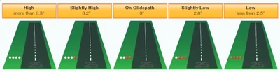
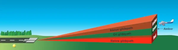
- Tri-color visual approach slope indicators normally consists of a single light unit projecting a three-color visual approach path into the final approach area of the runway upon which the indicator is installed []
- Typically useful from 1/2 to 1 mile during the day and up to 5 miles at night
- Below the glidepath is indicated by red, on the glidepath is indicated by green, and above the glidepath is indicated by amber
- Caution must be exercised not to confuse this system with other adjacent lights
- When the aircraft descends from green to red, the pilot may see a dark amber color during the transition
- Pilots should not mistake this area for an "above the glidepath" indication

Pulsating Systems
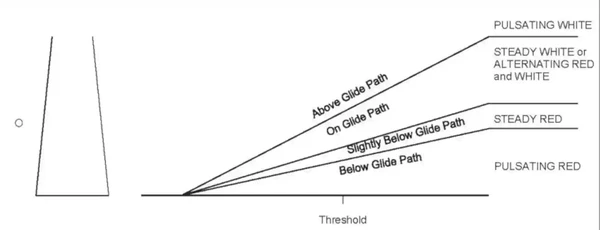
- Pulsating visual approach slope indicators normally consist of a single light unit projecting a two-color visual approach path []
- Useful range is 4 miles during the day and 10 miles at night
- The on glide path indication may be a steady white light or alternating red and white light
- The slightly below glide path indication is a steady red light
- If the aircraft descends further below the glide path, the red light starts to pulsate
- The above glide path indication is a pulsating white light
- The pulsating rate increases as the aircraft gets further above or below the desired glide slope
- As with the tri-color system, caution must be exercised not to confuse this system with other adjacent lights

Alignment of Elements Systems
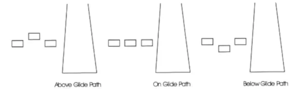
- Alignment of elements systems are installed on some small general aviation airports
- Low cost painted plywood panels, normally black and white or fluorescent orange []
- Some are lighted for night use
- Useful range is approximately 3/4 of a mile
- System works by illusions of the plywood where the aircraft is positioned

Visual Glide Slope Indicator Regulation
- Each pilot operating an airplane approaching to land on a runway served by a visual approach slope indicator must maintain an altitude at or above the glide path until a lower altitude is necessary for a safe landing
Visual Glide Slope Indicators Knowledge Check


Visual Glide Slope Indicators Conclusion
- Generally, glide slopes are set for around 3°, however, the local conditions dicate what is safety
- Exact numbers for each approach are published in the Chart Supplement
- VASI's are the most common approach light system
- Although only regulatory in Class D airspace according to FAR 91.129, each pilot operating an airplane approaching to land on a runway served by a visual approach slope indicator should maintain an altitude at or slightly above the glide path until a lower altitude is necessary for a safe landing
- Never land if PAPIs are flashing, as this could indicate the presence of an aircraft on the runway in accordance with runway status light system operation
- Still looking for something? Continue searching:
Visual Glide Slope Indicators References
- Federal Aviation Administration - Pilot/Controller Glossary.
- Aeronautical Information Manual (2-1-2) Visual Glideslope Indicators.
- CFI Notebook.net - Chart Supplement U.S..
- CFI Notebook.net - Notices to Airmen.
- Flight Information Handbook (FIH)
- Instrument Flying Handbook.
- FAA JO (6850.2B) Visual Guidance Lighting Systems.
- Pilot Handbook of Aeronautical Knowledge
- Airplane Flying Handbook