Pre-Flight Planning for Cold Temperature Altimeter Errors:
Flight planning into a CTA may be accomplished before flight. Use the predicted coldest temperature for plus or minus 1 hour of the estimated time of arrival and compare against the CTA published temperature. If the predicted temperature is at or below CTA temperature, calculate an altitude correction using [Figure 1]
This correction may be used at the CTA if the actual arrival temperature is the same as the temperature used to calculate the altitude correction during preflight planning
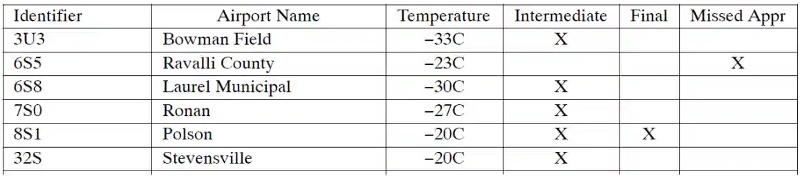
Example Cold Temperature Restricted Airport List - Required Segments
Cold Temperature Airports (CTA):
The FAA has determined that operating in cold temperatures has placed some 14 CFR Part 97 instrument approach procedures in the United States National Airspace System at risk for loss of required obstacle clearance (ROC)
An airport that is determined to be at risk will have an ICON and temperature published on the instrument approach procedure (IAP) in the terminal procedures publication (TPP)
CTA identification in TPP: A CTA is identified by a "snowflake" icon and temperature limit, in Celsius, on U.S. Government approach charts
Airports are listed by ICAO code, Airport Name, Temperature in Celsius, and affected segment(s)
Airport Criteria:
The CTA risk analysis is performed on airports that have at least one runway of 2500 ft
Pilots operating into an airport with a runway length less than 2500 ft may make a cold temperature altitude correction in cold temperature conditions, if desired
Comply with operating and reporting procedures for CTAs
ATC Reporting Requirements:
Pilots must advise ATC with the corrected altitude when applying an altitude correction on any approach segment with the exception of the final segment
Methods to Apply Correction
The FAA recommends operators/pilots use either the All Segments Method or the Individual Segments Method when making corrections at CTAs
Cold Temperature Airport Procedures:
PILOTS MUST NOT MAKE AN ALTIMETER CHANGE to accomplish an altitude correction
Pilots must ensure that the altimeter is set to the current altimeter setting provided by ATC in accordance with 14 CFR 91.121
Actions on when and where to make corrections: Pilots will make an altitude correction to the published, "at", "at or above", and "at or below" altitudes on all designated segment(s) to all runways for all published instrument approach procedures when the reported airport temperature is at or below the published CTA temperature on the approach plate
A pilot may request an altitude correction (if desired) on any approach at any United States airport when extreme cold temperature is encountered
Pilots making a correction must comply with ATC reporting requirements
Correctable altitudes: ATC does not apply a cold temperature correction to their Minimum Vectoring Altitude (MVA) or Minimum IFR Altitude (MIA) charts
Pilots must request approval from ATC to apply a cold temperature correction to any ATC assigned altitude. Pilots must not correct altitudes published on Standard Instrument Departures (SIDs), Obstacle Departure Procedures (ODPs), and Standard Terminal Arrivals (STARs)
Use of corrected MDA/DA: Pilots will use the corrected MDA or DA as the minimum altitude for an approach
Pilots must meet the requirements in 14 CFR Part 91.175 in order to operate below the corrected MDA or DA
Pilots must see and avoid obstacles when descending below the minimum altitude on the approach
Note: The corrected DA or MDA does not affect the visibility minima published for the approach. With the application of a cold temperature correction to the DA or MDA, the airplane should be in a position on the glide-slope/glide-path or at the published missed approach point to identify the runway environment
How to apply Cold Temperature Altitude Corrections on an Approach:
All Segments Method: Pilots may correct all segment altitudes from the initial approach fix (IAF) altitude to the missed approach (MA) final holding altitude. Pilots familiar with the information in this section and the procedures for accomplishing the all segments method, only need to use the published "snowflake" icon, /CTA temperature limit on the approach chart for making corrections. Pilots are not required to reference the CTA list. The altitude correction is calculated as follows:
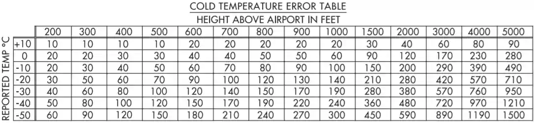
Manual correction: Pilots will make a manual correction when the aircraft is not equipped with a temperature compensating system or when a compensating system is not used to make the correction. Use the ICAO Cold Temperature Error Table to calculate the correction needed for the approach segment(s) [Figure 1]
Correct all altitudes from the final approach fix (FAF)/PFAF up to and including the IAF altitude: Calculate the correction by taking the FAF/PFAF altitude and subtracting the airport elevation. Use this number to enter the height above airport column in [Figure 1] until reaching the reported temperature from the "Reported Temperature" row. Round this number as applicable and then add to all altitudes from the FAF altitude through the IAF altitude
Correct all altitudes in the final segment: Calculate the correction by taking the MDA or DA for the approach being flown and subtract the airport elevation. Use this number to enter the height above airport column in [Figure 1] until reaching the reported temperature from the "Reported Temperature" row. Use this number or round up to next nearest 100. Add this number to MDA or DA, as applicable, and any applicable step-down fixes in the final segment. (3) Correct final holding altitude in the MA Segment: Calculate the correction by taking the final missed approach (MA) holding altitude and subtract the airport elevation. Use this number to enter the height above airport column in [Figure 1] until reaching the reported temperature from the "Reported Temperature" row. Round this number as applicable and then add to the final MA altitude only
Aircraft with temperature compensating systems: If flying an aircraft equipped with a system capable of temperature compensation, follow the instructions for applying temperature compensation provided in the airplane flight manual (AFM), AFM supplement, or system operating manual. Ensure that temperature compensation system is on and active prior to the IAF and remains active throughout the entire approach and missed approach
Pilots that have a system that is able to calculate a temperature-corrected DA or MDA may use the system for this purpose
Pilots that have a system unable to calculate a temperature corrected DA or MDA will manually calculate an altitude correction for the MDA or DA
Note: Some systems apply temperature compensation only to those altitudes associated with an instrument approach procedure loaded into the active flight plan while other systems apply temperature compensation to all procedure altitudes or user entered altitudes in the active flight plan, including altitudes associated with a STAR. For those systems that apply temperature compensation to all altitudes in the active flight plan, delay activating temperature compensation until the aircraft has passed the last altitude constraint associated with the active STAR
Individual Segment(s) Method: Pilots are allowed to correct only the marked segment(s) indicated in the CTA list. https://www.faa.gov/air_traffic/flight_info/aeronav/digital_products/dtpp /search/. Pilots using the Individual Segment(s) Method will reference the CTA list to determine which segment(s) need a correction. See FIG 7-3-1
Manual Correction: Pilots will make a manual correction when the aircraft is not equipped with a temperature compensating system or when a compensating system is not used to make the correction. Use [Figure 1], ICAO Cold Temperature Error Table, to calculate the correction needed for the approach segment(s)
Intermediate Segment: All altitudes from the FAF/PFAF up to but not including the intermediate fix (IF) altitude. Calculate the correction by taking FAF/PFAF altitude and subtracting the airport elevation. Use this number to enter the height above airport column in [Figure 1] until reaching the reported temperature from the "Reported Temperature" row. Round this number as applicable and then add to FAF altitude and all step-down altitudes within the intermediate segment (inside of the waypoint labeled "(IF)")
Final segment: Calculate correction by taking the MDA or DA for the approach flown and subtract the airport elevation. Use this number to enter the height above airport column in [Figure 1] until reaching the reported temperature from the "Reported Temperature" row. Use this number or round up to next nearest 100. Add this number to MDA or DA, as applicable, and any applicable step-down fixes in the final segment
Missed Approach Segment: Calculate the correction by taking the final MA holding altitude and subtract the airport elevation. Use this number to enter the height above airport column in [Figure 1] until reaching the reported temperature from the "Reported Temperature" row. Round this number as applicable and then add to the final MA altitude only
Aircraft with temperature compensating system: If flying an aircraft equipped with a system capable of temperature compensation, follow the instructions for applying temperature compensation provided in the AFM, AFM supplement, or system operating manual. Ensure the temperature compensation system is on and active prior to the segment(s) being corrected. Manually calculate an altimetry correction for the MDA or DA. Determine an altimetry correction from the ICAO table based on the reported airport temperature and the height difference between the MDA or DA, as applicable, and the airport elevation, or use the compensating system to calculate a temperature corrected altitude for the published MDA or DA if able
Acceptable Use of Table for manual CTA altitude correction: [Figure 1]
Pilots may calculate a correction with a visual interpolation of the chart when using reported temperature and height above airport. This calculated altitude correction may then be rounded to the nearest whole hundred or rounded up. For example, a correction of 130 ft. from the chart may be rounded to 100 ft. or 200 ft. A correction of 280 ft. will be rounded up to 300 ft. This rounded correction will be added to the appropriate altitudes for the "Individual" or "All" segment method. The correction calculated from the table for the MDA or DA may be used as is or rounded up, but never rounded down. This number will be added to the MDA, DA, and all step-down fixes inside of the FAF as applicable
No extrapolation above the 5000 ft. column is required. Pilots may use the 5000 ft. "height above airport in feet" column for calculating corrections when the calculated altitude is greater than 5000 ft. above reporting station elevation. Pilots must add the correction(s) from the table to the affected segment altitude(s) and fly at the new corrected altitude. Do not round down when using the 5000 ft. column for calculated height above airport values greater than 5000 ft. Pilots may extrapolate above the 5000 ft. column to apply a correction if desired
These techniques have been adopted to minimize pilot distraction by limiting the number of entries into the table when making corrections. Although not all altitudes on the approach will be corrected back to standard day values, a safe distance above the terrain/obstacle will be maintained on the corrected approach segment(s). Pilots may calculate a correction for each fix based on the fix altitude if desired
Note: Pilots may use Real Time Mesoscale Analysis (RTMA): Alternate Report of Surface Temperature, for computing altitude corrections, when airport temperatures are not available via normal reporting. The RTMA website is http://nomads.ncep.noaa.gov/pub/data/nccf/com/rtma/prod/airport_temps/
Communication: Pilots must request approval from ATC whenever applying a cold temperature altitude correction. Pilots do not need to inform ATC of the final approach segment correction (i.e., new MDA or DA). This request should be made on initial radio contact with the ATC facility issuing the approach clearance. ATC requires this information in order to ensure appropriate vertical separation between known traffic. Pilots should query ATC when vectored altitudes to a segment are lower than the requested corrected altitude. Pilots are encouraged to self-announce corrected altitude when flying into a non-towered airfield
The following are examples of appropriate pilot-to-ATC communication when applying cold-temperature altitude corrections
On initial check-in with ATC providing approach clearance: Missoula, MT (example below)
Vectors to final approach course: Outside of IAFs: "Request 9700 ft. for cold temperature operations"
Vectors to final approach course: Inside of ODIRE: "Request 7300 ft. for cold temperature operations"
Missed Approach segment: "Require final holding altitude, 12500 ft. on missed approach for cold temperature operations"
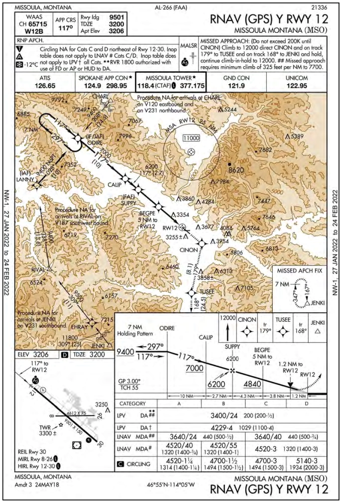
Pilots cleared by ATC for an instrument approach procedure; "Cleared the RNAV (GPS) Y RWY 12 approach (from any IAF)". Missoula, MT (example below)
IAF: "Request 9700 ft. for cold temperature operations at LANNY, CHARL, or ODIRE"
Instrument Approach Cold Temperature Operations:
Cold temperatures produce barometric altimetry errors, which affect instrument flight procedures
Currently there are two temperature limitations that may be published in the notes box of the middle briefing strip on an instrument approach procedure (IAP)
The two published temperature limitations are:
A temperature range limitation associated with the use of Baro-VNAV that may be published on an United States PBN IAP titled RNAV (GPS) or RNAV (RNP); and/or
A Cold Temperature Airport (CTA) limitation designated by a snowflake ICON and temperature in Celsius (C) that is published on every IAP for the airfield
Pilots should request the lowest forecast temperature +/- 1 hour for arrival and departure operations
If the temperature is forecast to be outside of the Baro-VNAV or at or below the CTA temperature limitation, consider the following:
When using Baro-VNAV with an aircraft that does not have an automated temperature compensating function, pilots should plan to use the appropriate minima and/or IAP
The LNAV/VNAV line of minima on an RNAV (GPS) may not be used without an approved automated temperature compensating function if the temperature is outside of the Baro-VNAV temperature range limitation. The LNAV minima may be used
The RNAV (RNP) procedure may not be accomplished without an approved automated temperature compensating function if the temperature is outside of the Baro-VNAV temperature range limitation
If the temperature is forecast to be at or below the published CTA temperature, pilots should calculate a correction for the appropriate segment/s or a correction for all the segments if using the "All Segments Method"
Pilots should review the operating procedures for the aircraft's temperature compensating system when planning to use the system for any cold temperature corrections
Any planned altitude correction for the intermediate and/or missed approach holding segments must be coordinated with ATC. Pilots do not have to advise ATC of a correction in the final segment
The charted Baro-VNAV temperature range limitation does not apply to pilots operating aircraft with an airworthiness approval to conduct an RNAV (GPS) approach to LNAV/VNAV minimums with the use of SBAS vertical guidance
Examples for Calculating Altitude Corrections on CTAs:
Cold Temperature Error Table
Missoula IAP Example
All 14 CFR Part 97 IAPs must be corrected at an airport. The following example provides the steps for correcting the different segments of an approach and will be applied to all 14 CFR Part 97 IAPs:
Missoula Intl (KMSO). Reported Temperature -12°C: RNAV (GPS) Y RWY 12
All Segments Method: All segments corrected from IAF through MA holding altitude
Manual Calculation:
Cold Temperature Restricted Airport Temperature Limit: -12°C
Altitude at the Final Approach Fix (FAF) (SUPPY) = 6200 ft
Airport elevation = 3206 ft
Difference: 6200 ft. - 3206 ft. = 2994 ft
Use [Figure 2], ICAO Cold Temperature Error Table, a height above airport of 2994 ft. and -12°C ad interpolate:
-10°C demands 290 ft correction, -20° demands a 420 ft correction (420-290=130 per degree), from -10°, add 26ft (13*2°) or 30 for even math... 320ft
Add 320 ft. to the FAF and all procedure altitudes outside of the FAF up to and including IAF altitude(s):
LANNY (IAF), CHARL (IAF), and ODIRE (IAF Holding-in-Lieu): 9400 + 320 = 9900 ft
CALIP (stepdown fix): 7000 + 320 = 7500 ft
SUPPY (FAF): 6200 + 320 = 6700 ft
Correct altitudes within the final segment altitude based on the minima used. LP MDA = 4520 ft
Difference: 4520 ft. - 3206 ft. = 1314 ft
[Figure 2]: 1314 ft. at -12°C is approximately 150ft. Use 150 ft. or round up to 200 ft
Add corrections to altitudes up to but not including the FAF:
BEGPE (stepdown fix): 4840 + 150 = 4990 ft
LNAV MDA: 4520 + 150 = 4670 ft
Correct JENKI/Missed Approach Holding Altitude: MA altitude is 12000:
JENKI: 12000 - 3206 = 8794 ft
[Figure 2]: 8794 ft. at -12°C. Enter table at -12°C and intersect the 5000 ft. height above airport column. The approximate value is 500 ft
Add correction to holding fix final altitude:
JENKI: 12000 + 500 = 12500 ft
Temperature compensating RNAV systems used to make altitude corrections will be set to the current airport temperature (-12°C) and activated prior to passing the IAF. A manual calculation of the cold temperature altitude correction is required for the MDA/DA
Individual Segments Method: Missoula requires correction in the intermediate and final segments. However, in this example, the missed approach is also shown
Manual Calculation: Use the appropriate steps in the All Segments Method above to apply a correction to the required segment
Intermediate. Use steps 7-3-6 a. 1. (a) (1) thru (6). Do not correct the IAF or IF when using individual segments method
Final. Use steps 7-3-6 a. 1. (a) (7) thru (10)
Missed Approach. Use steps 7-3-6 a, 1. (a) (11) thru (13)
Temperature Compensating System: Operators using a temperature compensating RNAV system to make altitude corrections will be set to the current airport temperature (-12°C) and activated at a point needed to correct the altitude for the segment. A manual calculation of the cold temperature altitude correction is required for the MDA/DA
Effects of Cold Temperature on Baro-Vertical Navigation (VNAV) Vertical Guidance:
Non-standard temperatures can result in a change to effective vertical paths and actual descent rates when using aircraft Baro-VNAV equipment for vertical guidance on final approach segments
A lower than standard temperature will result in a shallower descent angle and reduced descent rate
Conversely, a higher than standard temperature will result in a steeper angle and increased descent rate
Pilots should consider potential consequences of these effects on approach minima, power settings, sight picture, visual cues, etc., especially for high-altitude or terrain-challenged locations and during low-visibility conditions
Uncompensated Baro-VNAV note on 14 CFR Part 97 IAPs:
The area navigation (RNAV) global positioning system (GPS) and RNAV required navigation performance (RNP) notes, "For uncompensated Baro-VNAV systems, lateral navigation (LNAV)/VNAV NA below -XX°C (-XX°F) or above XX°C (XXX°F)" and "For uncompensated Baro-VNAV systems, procedure NA below -XX°C (-XX°F) or above XX°C (XXX°F)" apply to Baro-VNAV equipped aircraft
These temperatures and how they are used are independent of the temperature and procedures applied for a Cold Temperature Airport
The uncompensated Baro-VNAV chart note and temperature range on an RNAV (GPS) approach is applicable to the LNAV/VNAV line of minima
Baro-VNAV equipped aircraft without a temperature compensating system may not use the RNAV (GPS) approach LNAV/VNAV line of minima when the actual temperature is above or below the charted temperature range
The uncompensated Baro-VNAV chart note and temperature range on an RNAV (RNP) approach applies to the entire procedure
For aircraft without a Baro-VNAV and temperature compensating system, the RNAV (RNP) approach is not authorized when the actual temperature is above or below the charted uncompensated Baro-VNAV temperature range
Baro-VNAV temperature range versus CTA temperature:
The Baro-VNAV and CTA temperatures are independent and do not follow the same correction or reporting procedures
However, there are times when both procedures, each according to its associated temperature, should be accomplished on the approach
Operating and ATC reporting procedures:
Do not use the CTA operating or reporting procedure found in this section, 7-3-4a. thru 7-3-5e. when complying with the Baro-VNAV temperature note on an RNAV (GPS) approach
Correction is not required nor expected to be applied to procedure altitudes or VNAV paths outside of the final approach segment
Operators must advise ATC when making temperature corrections on RNP authorization required (AR) approaches while adhering to Baro-VNAV temperature note
Reporting altitude corrections is required when complying with CTAs in conjunction with the Baro-VNAV temperature note
The CTA altitude corrections will be reported in this situation
No altitude correction reporting is required in the final segment
Note: When executing an approach with vertical guidance at a CTA (i.e., ILS, localizer performance with vertical guidance (LPV), LNAV/VNAV), pilots are reminded to intersect the glideslope/glidepath at the corrected intermediate altitude (if applicable) and follow the published glideslope/glidepath to the corrected minima. The ILS glideslope and WAAS generated glidepath are unaffected by cold temperatures and provide vertical guidance to the corrected DA. Begin descent on the ILS glideslope or WAAS generated glidepath when directed by aircraft instrumentation. Temperature affects the precise final approach fix (PFAF) true altitude where a Baro-VNAV generated glidepath begins. The PFAF altitude must be corrected when below the CTA temperature restriction for the intermediate segment or outside of the Baro-VNAV temperature restriction when using the LNAV/VNAV line of minima to the corrected DA
Cold Temperature Engine Starting:
Starting an engine in the cold produces some challenges
Low vapor pressure combined with reduced battery efficiency can make cold temperature start-ups more difficult
Carburetor engines are more likely to experience difficulty starting as compared to fuel-injection
When engines fail to start, the chance of overpriming increases, and fuel may pool in the cylinders, disrupting the fuel/air ratio, posing a backfire or engine fire risk
Consider an external observer when starting engines in cold weather to provide advanced warning of fires
The aircraft's POH/PIM knows what is best for that specific aircraft but as a rule-of-thumb, cold weather starts can cause abnormal engine wear, reduced performance, and therefore decreased time between heavy maintenance like an overhaul
Some of this is due to metallurgy being out of tolerance, but also reduced oil flow
Cold engine temperatures can be mitigated by storing aircraft in heated hangars, or absent that, using a device that heats the engine before starting such as a pre-heater blowing hot air into the cowling, or an electronic engine-mounted heater
When using pre-heaters, follow the manufacturers guidance, to include your aircraft
Avoid excessive heat to non-metallic equipment
Do not leave the heater on for longer than recommended
Once complete with pre-heating, inspect the engine for any foreign objects, and once clear, start the engine before the aircraft's engine cools down again
Cold Weather Safety:
For cold weather safety, The FAA Safety Team recommends following the below tips may "SPARE" you from dangerous runway incursions
Speed:
When taxiing, keep it slow
Taxi slowly to avoid throwing up snow and slush into the wheel wells and onto aircraft surfaces
Taking it slow is also safer, providing more response time in case the tires decide to slide on an icy patch
Purpose:
Ensure you have a current airport diagram to reference prior to taxi as winter weather may obscure references
Plan your route ahead of time, knowing where the runway safety areas are
Runway safety happens on purpose because of your planning and airmanship
Aerodynamics:
Since braking is not effective on a wet or icy runway, take advantage of aerodynamic braking by holding the nose up as long as possible
Aircraft control can only be maintained if the main wheels are rolling
Any braking should be applied gently and evenly using care not to lock up the wheels
When the airplane slows down, control effectiveness from the rudder and ailerons are lost
The airplane does what comes naturally - it weathervanes into the wind
If there is ice, the amount of wind the airplane can tolerate drops dramatically
Land into the wind on icy surfaces, or divert to a less contaminated runway or one with less of a crosswind
Runway:
Offset, parallel runways continue to challenge GA pilots
Be aware that you may be looking at a dominate runway, not the one that you were cleared for
Snow covered terrain may add to the difficulty
Understand your clearance and reference the airport diagram. If you're not 100% sure, go around
Equipment:
Remove the airplane's wheel pants if equipped
Slush and ice can collect inside the wheel pant and freeze the brakes to the rotors making for an interesting landing with wheels that won't spin
Removal of the wheel pants will also allow you a clearer view to inspect tire condition and the possibility of leaking fluid
Check tire pressure as cold temperatures reduce pressure
Use pre-heater to ease starting, prevent engine flooding, and reduce the risk of air filter fires
Wear warming clothing and update survival gear as appropriate
Meteorological Considerations:
Frost:
Frost is the formation of thin ice crystals on the ground or other surfaces on solid objects below the freezing point of water
It develops in Arctic coastal areas during spring, autumn, and winter
Frost adds weight and disturbs smooth airflow over the aircraft and control surfaces
The closer dewpoint is to temperature, the increased risk of condensation, which when below freezing is frost
Remove all accumulation on the aircraft, especially flight surfaces as frost and ice may reduce lift by up to 30% and increase drag by up to 40%
Use a broom or a deicing liquid, if available, to avoid scratching the paint
Frost/ice should again be checked after the aircraft has taxied to the runway
Thin surfaces (tail) tend to accumulate ice/frost the fastests
Consider hand flying to maintain the tactile feel of ice accumulation
Taxi slowly to avoid throwing anything from the surface onto the wings
Avoid flying near cloud types as water droplets are concentrated most towards the top
Maintenance:
Review the Pilot Operating Handbook for any preventative maintenance that may be required
Change oil to a lower viscosity, if recommended by the manufacturer
Proper oil viscosity for the environment will help the aircraft during starting
Replace or add carbon monoxide detectors, especially if your engine heats air over the exhaust shroud
Add fuel additives, if recommended by the manufacturer
Technique:
Be more gentle with power changes that may abruptly change engine temperatures such as adding takeoff power to avoid shocking the engine
Icing Effects on Aircraft Control and Performance:
Structural icing, referring to the accumulation of ice on the exterior of the aircraft, will have impacts on control and performance
Forms on the external structure of the aircraft when supercooled droplets impinge on them and freeze
Small parts of the aircraft will develop ice (Pitot tube) before larger parts (wing)
Icing in strange places such as the windscreen is indicative of super-cooled droplets
The quicker you move, the more friction on the skin of the airplane, and thus the less icing would be expected; so a jet will not ice as fast as a Cessna in the same conditions
Icing decreases lift, thrust, and range, and increases drag, weight, fuel consumption, and stall speed
The most hazardous aspect of structural icing is its aerodynamic effects
Lift:
We know from our principles of flight that lift is generated mostly on the first 25% of our wingtip which is the same location ice will tend to build
[Figure 2-19] Ice alters the shape of an airfoil, reducing the maximum coefficient of lift and angle of attack at which the aircraft stalls
Note that at very low angles of attack, there may be little or no effect of the ice on the coefficient of lift
However, note that the ice significantly reduces the CL-MAX, and the angle of attack at which it occurs (the stall angle) is much lower
Thus, when slowing down and increasing the angle of attack for approach, the pilot may find that ice on the wing, which had little effect on lift in cruise now, causes stall to occur at a lower angle of attack and higher speed
Even a thin layer of ice at the leading edge of a wing, especially if it is rough, can have a significant effect in increasing stall speed
Its like flying at a very high altitude
Thrust:
Propeller icing reduces thrust for the same aerodynamic reason that wings tend to lose lift and increase drag
The accumulation of ice affects the coefficient of drag of the airfoil
[Figure 2-19] Note that the effect is significant even at very small angles of attack
A significant reduction in CL-MAX and a reduction in the angle of attack where stall occurs can result from a relatively small ice accretion
A reduction of CL-MAX by 30% is not unusual, and a large horn ice accretion can result in reductions of 40% to 50%
Drag tends to increase steadily as ice accretes
An airfoil drag increase of 100% is not unusual, and for large horn ice accretions, the increase can be 200% or even higher
Ice on an airfoil can have other effects not depicted in these curves
Even before airfoil stall, there can be changes in the pressure over the airfoil that may affect a control surface at the trailing edge
Furthermore, on takeoff, approach, and landing, the wings of many aircraft are multi-element airfoils with three or more elements
Ice may affect the different elements in different ways
Ice may also affect the way in which the air streams interact over the elements
Ice can partially block or limit control surfaces, which limits or makes control movements ineffective
Also, if the extra weight caused by ice accumulation is too great, the aircraft may not be able to become airborne and, if in flight, the aircraft may not be able to maintain altitude
Therefore any accumulation of ice or frost should be removed before attempting flight
Another hazard of structural icing is the possible un-commanded and uncontrolled roll phenomenon, referred to as roll upset, associated with severe in-flight icing
Pilots flying aircraft certificated for flight in known icing conditions should be aware that severe icing is a condition outside of the aircraft's certification icing envelope
Roll upset may be caused by airflow separation (aerodynamic stall), which induces self deflection of the ailerons and loss of or degraded roll handling characteristics [Figure 2-20]
These phenomena can result from severe icing conditions without the usual symptoms of ice accumulation or a perceived aerodynamic stall
Most aircraft have a nose-down pitching moment from the wings because the CG is ahead of the CP
It is the role of the tail-plane to counteract this moment by providing a downward force
[Figure 2-21] The result of this configuration is that actions which move the wing away from stall, such as deployment of flaps or increasing speed, may increase the negative angle of attack of the tail
With ice on the tail-plane, it may stall after full or partial deployment of flaps
[Figure 2-22] Since the tail-plane is ordinarily thinner than the wing, it is a more efficient collector of ice
On most aircraft the tail-plane is not visible to the pilot, who therefore cannot observe how well it has been cleared of ice by any deicing system
Thus, it is important that the pilot be alert to the possibility of tail-plane stall, particularly on approach and landing
Weight:
The more ice that accumulates, the more weight on the aircraft
The actual weight of the ice on the airplane is insignificant however, when compared to the airflow disruption it causes
Flight Controls:
As airfoils become less effective, so may flight control surfaces
This means more deflection will be required until the point where the control surface is ineffective
Fuel Consumption:
The more weight and drag increases, the more thrust is required
Since thrust can also be degrading, the engine must work even harder, increasing fuel consumption
Icing Effects on Aircraft Systems:
Induction Icing:
Engine icing occurs when ice forms on the induction or compressor sections of an engine, reducing performance
Ice in the induction system can reduce the amount of air available for combustion
The most common example of reciprocating engine induction icing is carburetor ice
Most pilots are familiar with this phenomenon, which occurs when moist air passes through a carburetor venturi and is cooled
As a result of this process, ice may form on the venturi walls and throttle plate, restricting airflow to the engine
This may occur at temperatures between 20°F (-7°C) and 70°F (21°C)
Applying carburetor heat, which uses the engine's exhaust as a heat source, is used to melt the ice or prevent its formation
On the other hand, fuel-injected aircraft engines are usually less vulnerable to icing but still can be affected if the engine's air source becomes blocked with ice
Manufacturers provide an alternate air source for use in case the normal system malfunctions
In turbojet aircraft, air ingested into the engines creates an area of reduced pressure at the inlet, which lowers the temperature below that of the surrounding air
In marginal icing conditions (i.e., conditions where icing is possible), this reduction in temperature may be sufficient to cause ice to form on the engine inlet, disrupting the airflow into the engine
Another hazard occurs when ice breaks off of an aircraft surface and is ingested into a running engine, which can cause damage to fan blades, engine compressor stall, or combustor flameout
When using anti-icing systems, run-back water can refreeze on unprotected surfaces of the inlet and, if excessive, reduce airflow into the engine or distort the airflow pattern in such a manner as to cause compressor or fan blades to vibrate, possibly damaging the engine
Another problem in turbine engines is the icing of engine probes used to set power levels (for example, engine inlet temperature or Engine Pressure Ratio (EPR) probes), which can lead to erroneous readings of engine instrumentation operational difficulties or total power loss
Communication & Navigation:
Antennas are quick to accumulate ice and typically do not have protection, leading to navigation and communication problems or failures
Avionics will perform slower until warmed up
Flight Instruments:
Flight instruments rely on data from external sources such as the Pitot tube, static ports, and stall warnings
Interruptions to external sources due to icing can result in instrument failures
Flight Control Systems:
Cold weather causes components, even flight controls and cables, to contract
Components contracting can cause previously unexperienced binding or tension
WeatherCams:
The FAA Weather Camera Program, in collaboration with State Departments of Transportation (DOT) hosts weather camera systems in the lower 48 states and lays the path for other state DOTs to implement the service for their aviation communities
The camera images are publicly available on a new website https://weathercams.faa.gov, with tutorials on how to use the information presented on the site
Cold/Winter Weather Storage and Preflight Preparation:
Preparing for Cold/Winter Storage:
Find and follow manufacturer procedures, if available
Clean the aircraft of any unncessary equipment, especially that which could freeze and explode (soda cans) inside of the aircraft
Consider approved methods to prevent corrosion (moisture) and stabilize fuel
Consider changing the oil (greater protection to internal parts) and filling the fuel tanks (to avoid moisture)
Chocking the breaks avoids any damage to the brake system cauesed by long-term parking brake use
Check on the aircraft over time to identify leaks caused by metal fittings contracting early
Keep the aircraft in an enclosed environment (tent, hangar, etc.) when possible
A canopy cover should be applied when windy weather is anticipated, but not left on so as to avoid damage from it freezing and crazing the windows
Orient the propeller spinner vertically to avoid contamination buildup
When storing in a hangar, lay antimal traps and still cover all appropriate ports and vents to avoid foreign intrusion
Consider moving the aircraft periodically to protect tires and shocks from becoming lodged in place or damaged
Consider supervised adjustment of control cables to compensate for cold contraction
Keep batteries (engine, ELT, etc.) charged or remove if parked outside
De-winterizing:
Conduct a thorough inspection, checking all cables, hoses, tubing, seals, etc. for cracks, hardening, distortion, and lumps
Tighten any loose clamps or fittings
Pay attention to the heater system or any Carbon Monoxide hazard
Check for nests or any foreign objects
Conclusion:
Always consult the aircraft's Pilot Operating Handbook for special procedures and limitations (such as engine starting) regarding cold temperature operations