The heading indicator, also called a directional gyro, is an instrument used to determine aircraft direction to aid the pilot in navigation
When set properly, heading indicators indicate primary heading and indirect bank (due to heading change)
Functions using the vacuum system and operates on the principle of torque-induced precession (gyroscopic precession)
Although very reliable, a magnetic compass has so many inherent errors, such as magnetic dip, that it has been supplemented with gyroscopic heading indicators
The heading of the aircraft is shown against the nose of the symbolic aircraft on the instrument glass, which serves as the lubber line to display directional (heading) information in reference to 360°
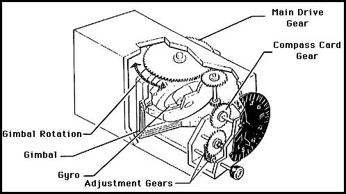
Senses rotation about vertical axis
Because airplane does more than yaw, additional gimbal is needed to allow free rotation (2 gimbals total)
Gyro heading indicators, with the exception of slaved gyro indicators, are not north seeking, therefore they must be manually set to the appropriate heading by referring to a magnetic compass
Rigidity causes them to maintain this heading indication, without the oscillation and other errors inherent in a magnetic compass
Older directional gyros use a drum-like card marked in the same way as the magnetic compass card
The gyro and the card remain rigid inside the case with the pilot viewing the card from the back
This creates the possibility the pilot might start a turn in the wrong direction similar to using a magnetic compass
Heading indicators like the one in Figure 3-31 work on the same principle as the older horizontal card indicators, except that the gyro drives a vertical dial that looks much like the dial of a vertical card magnetic compass
This could also be accomplished with a magnetic compass
Flux Gate System:
HSI Slave Switch and Indicator
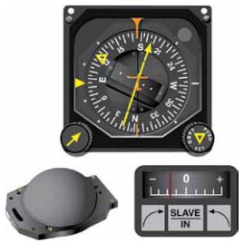
Some more expensive heading indicators are 'slaved' to a sensor (called a 'flux gate,' north seeking) [Figure 2]
The flux gate continuously senses the earth's magnetic field, and a servomechanism constantly corrects the heading indicator
These 'slaved gyros' reduce pilot workload by eliminating the need for manual realignment every ten to fifteen minutes
A concentration of lines of magnetic force, after being amplified, becomes a signal relayed to the heading indicator unit, which is also remotely mounted
This signal operates a torque motor in the heading indicator unit that processes the gyro unit until it is aligned with the transmitter signal
The magnetic slaving transmitter is connected electrically to the HSI (when in slaved mode)
There are a number of designs of the remote indicating compass; therefore, only the basic features of the system are covered here
Instrument pilots must become familiar with the characteristics of the equipment in their aircraft
As instrument panels become more crowded and the pilot's available scan time is reduced by a heavier flight deck workload, instrument manufacturers have worked toward combining instruments
When not in slaved mode, the HSI can be manually adjusted to reflect the desired reading
HSI Slave Switch and Indicator
Horizontal Situational Indicators:
Horizontal Situational Indicators (HSIs) combine navigation and heading instruments into one
HSIs align themselves with the flux gate and are usually electrically driven (electric gyro)
The gyro in a heading indicator is mounted in a double gimbal, as in an attitude indicator, but its spin axis is horizontal permitting sensing of rotation about the vertical axis of the aircraft
Instrument Flying Handbook, Pictorial Navigation Indicator (HSI Top), Slaving Control and Compensator Unit
Remote Indicating (RMI) Compass:
Developed to compensate for errors and limitations with older heading indicators
The two panel-mounted components of a typical system:
Pictorial navigation indicator, and;
Slaving control and compensator unit
The pictorial navigation indicator is commonly referred to as a Horizontal Situational Indicator (HSI)
The slaving control and compensator unit has a pushbutton that provides a means of selecting either the "slaved gyro" or "free gyro" mode
This unit also has a slaving meter and two manual heading-drive buttons
The slaving meter indicates the difference between the displayed heading and the magnetic heading
A right deflection indicates a clockwise error of the compass card; a left deflection indicates a counterclockwise error
Whenever the aircraft is in a turn and the card rotates, the slaving meter shows a full deflection to one side or the other
When the system is in "free gyro" mode, the compass card may be adjusted by depressing the appropriate heading-drive button
A separate unit, the magnetic slaving transmitter is mounted remotely, usually in a wingtip to eliminate the possibility of magnetic interference
It contains the flux valve, which is the direction-sensing device of the system
Instrument Flying Handbook, Driven by signals from a flux valve, the compass card in this RMI indicates the heading of the aircraft opposite the upper center index mark. The green pointer is driven by the ADF
Function:
The HI works using a gyroscope to establish an inertial platform, which will remain fixed in space
The HI is arranged so that only the horizontal axis is used to drive the display, which consists of a circular compass card calibrated in degrees
The gyroscope is spun either electrically; or using air from a vacuum pump (sometimes a pressure pump in high altitude aircraft) driven from the aircraft's engine
A knob on the front of the instrument, below the dial, can be pushed in to engage the gimbals
This locks the gimbals allowing the pilot to rotate the gyro and card until the number opposite the lubber line agrees with the magnetic compass
When the knob is pulled out, the gyro remains rigid and the aircraft is free to turn around the card
The knob is spring loaded so it disengages from the gimbals as soon as it is released
Compass Card
Instrument Errors:
Tumble:
Indicator may tumble if limits are exceeded
This means the gyro has been distributed so much to the point that it needs to find its axis again
This should not occur in most flight profiles but is a possibility when you start talking aerobatics
Precession:
Because the earth rotates (15° per hour) and because of small accumulated errors caused by friction, the HI will drift over time and must be reset from the magnetic compass periodically
Normal procedure is to reset the heading indicator once each fifteen minutes of flight
Must be done from straight and level, unaccelerated flight in order to be sure the magnetic compass heading displayed is accurate
Preflight Actions:
Once set, the heading indicator should not precess more than 3° in 15 minutes
Inertial Reference Unit (IRU), Inertial Navigation System (INS), and Attitude Heading Reference System (AHRS)
IRUs are self-contained systems comprised of gyros and accelerometers that provide aircraft attitude (pitch, roll, and heading), position, and velocity information in response to signals resulting from inertial effects on system components
Once aligned with a known position, IRUs continuously calculate position and velocity. IRU position accuracy decays with time
This degradation is known as "drift"
INSs combine the components of an IRU with an internal navigation computer
By programming a series of waypoints, these systems will navigate along a predetermined track
AHRSs are electronic devices that provide attitude information to aircraft systems such as weather radar and autopilot, but do not directly compute position information
Aircraft equipped with slaved compass systems may be susceptible to heading errors caused by exposure to magnetic field disturbances (flux fields) found in materials that are commonly located on the surface or buried under taxiways and ramps
These materials generate a magnetic flux field that can be sensed by the aircraft's compass system flux detector or "gate", which can cause the aircraft's system to align with the material's magnetic field rather than the earth's natural magnetic field
The system's erroneous heading may not self-correct
Prior to take off pilots should be aware that a heading misalignment may have occurred during taxi
Pilots are encouraged to follow the manufacturer's or other appropriate procedures to correct possible heading misalignment before take off is commenced