Cold Temperature Operations
Cold-weather flight requires pilots to manage frost, ice contamination, reduced battery performance, and aircraft system limitations.
Introduction to Cold Temperature Operations
- When the temperature drops, air density increases, potentially causing altimeters to read lower than the aircraft's actual altitude, which can affect instrument flight procedures.
- Planning for operating at airports with cold temperatures begins during the preflight planning phase, which includes a review of cold-temperature airports.
- Pilots flying to cold-temperature airports must follow unique procedures.
- Consider not only airport surface operations but also instrument approach cold temperature operations.
Cold Temperature Operations Key Highlights
- Cold temperature operations affect aircraft performance, engine starting, fuel management, visibility, and ground handling.
- Cold air increases aircraft performance by improving engine power, propeller efficiency, and wing lift.
- Aircraft performance may improve in cold air, but runway contamination can reduce acceleration, braking, and directional control.
- Frost, snow, and ice on aircraft surfaces disrupt airflow and can significantly reduce lift and control effectiveness.
- Pilots should remove all contamination from critical surfaces before flight to preserve expected aerodynamic performance.
- Cold weather can increase oil viscosity, reduce battery performance, and make engine starting more difficult.
- Preheating may be necessary to protect the engine and improve starting reliability in very cold conditions.
- Fuel system awareness is important because water contamination can freeze and restrict fuel flow.
- Cold temperature altimetry errors can cause the aircraft to be lower than indicated, especially during instrument approaches.
- Effective cold weather planning includes aircraft preparation, runway condition review, performance calculations, and conservative decision-making.
Effect of Cold Temperature on Barometric Altimeters
- Temperature affects the accuracy of barometric altimeters, as well as indicated altitude and true altitude.
- The standard temperature at sea level is 15°C (59°F).
- The temperature gradient from sea level is minus 2°C (3.6°F) per 1,000 feet.
- For example, at 5,000 feet above sea level, the ambient temperature on a standard day would be 5°C.
- 2°C per 1000 feet loss, subtracted from the standard sea level temperature of 15°C.
- When the ambient (at altitude) temperature is colder than standard, the aircraft's true altitude is lower than the indicated barometric altitude.
- When the ambient temperature is warmer than the standard day, the aircraft's true altitude is higher than the indicated barometric altitude.
- For example, at 5,000 feet above sea level, the ambient temperature on a standard day would be 5°C.
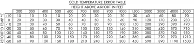
- The FAA provides a cold temperature error table to indicate the potential error that may occur when operating in non-standard cold temperatures. []
- To use the table, find the reported temperature in the left column, and read across the top row to locate the height above the airport (subtract the airport elevation from the flight altitude).
- Find the intersection of the temperature row and the height above airport column.
- This number represents the deviation from the indicated altitude that may occur due to errors induced by cold temperatures.

Preflight Planning for Cold Temperature Altimeter Errors
- Pilots must flight plan for CTAs before the flight.
- Use the predicted coldest temperature plus or minus 1 hour of the estimated time of arrival, and compare against the CTA published temperature.
- If the predicted temperature is at or below the CTA temperature, calculate the altitude correction using the appropriate formula. []
- Planned altitude corrections apply at the CTA only if the actual arrival temperature is the same as the temperature used to calculate the altitude correction during preflight planning.
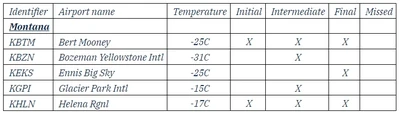
Cold Temperature Airports (CTA)
- Operating in cold temperatures poses a risk to 14 CFR Part 97 instrument approach procedures in the United States National Airspace System, potentially compromising the required obstacle clearance (ROC).
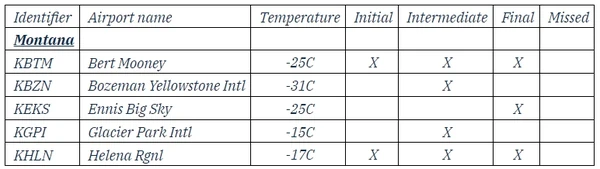
- If an airport is at risk, the U.S. Government instrument approach procedure (IAP) in the Terminal Procedures Publication (TPP) will show a "snowflake" icon and list its temperature in degrees Celsius.
- The FAA provides a current list of CTAs at: https://www.faa.gov/air_traffic/flight_info/aeronav/digital_products/dtpp/search/ under "Additional Resources," listed by ICAO code, airport name, temperature in Celsius, and affected segment(s).
-
Airport Criteria:
- The FAA performs a CTA risk analysis on airports that have at least one runway of 2500 ft.
- Pilots operating into an airport with a runway length less than 2500 ft may make a cold temperature altitude correction in cold temperature conditions, if desired.
- Comply with operating and reporting procedures for CTAs.
- Pilots operating into an airport with a runway length less than 2500 ft may make a cold temperature altitude correction in cold temperature conditions, if desired.
- The FAA performs a CTA risk analysis on airports that have at least one runway of 2500 ft.
-
ATC Reporting Requirements:
- Pilots must advise ATC of the corrected altitude when applying an altitude correction on any approach segment, except the final segment.
-
Methods to Apply Correction:
- The FAA recommends operators/pilots use either the All Segments Method or the Individual Segments Method when making corrections at CTAs.
Cold Temperature Airport Procedures
- PILOTS MUST NOT MAKE AN ALTIMETER CHANGE to accomplish an altitude correction.
- Pilots set the altimeter to the current altimeter setting provided by ATC in accordance with 14 CFR 91.121.
- Pilots will make an altitude correction to the published "at", "at or above", and "at or below" altitudes on all designated segment(s) to all runways for all published instrument approach procedures when the reported airport temperature is at or below the published CTA temperature on the approach plate.
- A pilot may request an altitude correction (if desired) on any approach at any United States airport when encountering extreme cold temperatures.
- Pilots applying corrections must comply with ATC reporting requirements.
- ATC does not apply a cold temperature correction to their Minimum Vectoring Altitude (MVA) or Minimum IFR Altitude (MIA) charts.
- Pilots must request approval from ATC to apply a cold temperature correction to any ATC-assigned altitude.
- Pilots must not correct altitudes published on Standard Instrument Departures (SIDs), Obstacle Departure Procedures (ODPs), and Standard Terminal Arrivals (STARs).
- Pilots will use the corrected MDA or DA as the minimum altitude for an approach.
- The corrected DA or MDA does not affect the visibility minima published for the approach.
- With the application of a cold temperature correction to the DA or MDA, the airplane should be positioned on the glide slope/glide path or at the published missed approach point to identify the runway environment.
- The corrected DA or MDA does not affect the visibility minima published for the approach.
- Pilots may calculate a correction using a visual interpolation of the chart, based on the reported temperature and height above the airport.
- Considering rounding corrections up to the nearest whole hundred.
- For example, a correction of 130 ft from the chart rounds to 100 ft or 200 ft.
- A correction of 280 ft rounds up to 300 ft.
- Add corrections to the appropriate altitudes for the "Individual" or "All" segment method, as well as to the MDA, DA, and all step-down fix altitudes inside of the FAF/PFAF.
- Pilots then add the correction to the MDA, DA, and all step-down fix altitudes inside of the FAF/PFAF.
- Considering rounding corrections up to the nearest whole hundred.
- Pilots do not need to extrapolate above the 5000 ft column.
- Pilots may use the 5000 ft "height above airport in feet" column for calculating corrections when the calculated altitude is greater than 5000 ft above the reporting station elevation.
- Pilots must add the correction(s) from the table to the affected segment altitude(s) and fly at the new corrected altitude.
- Note: Pilots may use Real-Time Mesoscale Analysis (RTMA) - Alternate Report of Surface Temperature - to compute altitude corrections when airport temperatures are not available through regular reporting.
- Pilots may use the 5000 ft "height above airport in feet" column for calculating corrections when the calculated altitude is greater than 5000 ft above the reporting station elevation.
-
Applying Cold Temperature Altitude Corrections on an Approach:
- Pilots must correct all 14 CFR Part 97 IAPs at an airport.
- Pilots determine corrections using the all-segments method and the individual-segments method.
-
All Segments Method:
- Pilots may correct all segment altitudes from the IAF altitude to the MA final holding altitude.
- Pilots only need to use the published "snowflake" icon/CTA temperature limit on the approach chart for making corrections.
- When the aircraft is not using a compensating system, manual corrections are necessary.
- The ICAO Cold Temperature Error Table is used to calculate the correction needed for the approach segment(s).
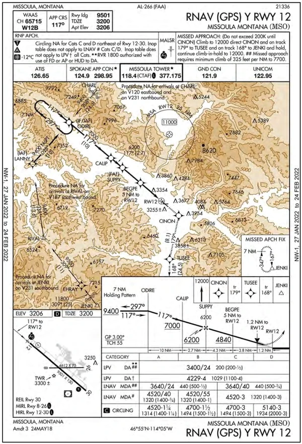
- Supposing the RNAV (GPS) Y RWY 12 into Missoula, Montana: []
-
Manual Corrections Outside the FAF:
- Cold temperature restricted airport temperature limit: -12°C.
- Final Approach Fix (FAF) (SUPPY) Altitude = 6200 ft.
- Airport elevation: 3206 ft.
- Difference: 6200 - 3206 = 2994 ft.
- Using the ICAO Cold Temperature Error Table:
- Start with the 3,000 ft (2,994 ft rounded up) height above the airport and move down the chart to the reported temperature.
- If the temperature is -10°C, a 290 ft correction is required.
- If the temperature is -20°, a 420 ft correction is required.
- 420 - 290 = 130 ft across 10°, which is 13 ft per °C.
- The correction required is 290 + 26 ft, or 316 ft, which rounds up to 320 ft.
- Start with the 3,000 ft (2,994 ft rounded up) height above the airport and move down the chart to the reported temperature.
- Add 320 ft. to the FAF and all procedure altitudes outside of the FAF up to and including IAF altitude(s):
- LANNY (IAF), CHARL (IAF), and ODIRE (IAF Holding-in-Lieu): 9400 + 320 = 9720 ft.
- CALIP (stepdown fix): 7000 + 320 = 7320 ft.
- SUPPY (FAF): 6200 + 320 = 6520 ft.
- To calculate manual corrections inside the FAF, use the same procedure as outside the FAF, but subtract the airport elevation from the MDA or DA instead of using the FAF value described above.
-
Manual Corrections Inside the FAF:
- Cold temperature restricted airport temperature limit: -12°C.
- LP MDA: 4,520 ft.
- Difference: 4520 - 3206 = 1,314 ft.
- Using the ICAO Cold Temperature Error Table:
- While you can interpolate between the height above the airport and reported temperature fields, it is often best to round up (in this case, to 1,500 ft) for added safety and simplify the calculation.
- If the temperature is -10°C, a 150 ft correction is required.
- If the temperature is -20°C, a 210 ft correction is required.
- 210 - 150 = 60 ft across 10°, which is 6 ft per °C.
- The correction required is 150 + 12 ft, or 162 ft, which rounds up to 170 ft.
- While you can interpolate between the height above the airport and reported temperature fields, it is often best to round up (in this case, to 1,500 ft) for added safety and simplify the calculation.
- Add 170 ft. to the LP MDA, including any intermediate steps within the FAF as applicable.
-
Manual Corrections for Missed Approach Holding Altitude:
- Follow the same steps as outside the FAF.
-
Temperature-Compensating Systems:
- If flying an aircraft equipped with a system capable of temperature compensation, follow the instructions for applying temperature compensation provided in the airplane flight manual (AFM), AFM supplement, or system operating manual. Ensure that the temperature compensation system is on and active before the IAF and remains active throughout the entire approach and missed approach.
- Pilots who have a system that can calculate a temperature-corrected DA or MDA may use the system for this purpose.
- Pilots who have a system unable to calculate a temperature-corrected DA or MDA will manually calculate an altitude correction for the MDA or DA.
- Note: Some systems apply temperature compensation only to those altitudes associated with an instrument approach procedure loaded into the active flight plan, while other systems apply temperature compensation to all procedure altitudes or user-entered altitudes in the active flight plan, including altitudes associated with a Standard Terminal Arrival (STAR). For those systems that apply temperature compensation to all altitudes in the active flight plan, delay activating temperature compensation until the aircraft has passed the last altitude constraint associated with the active STAR.
- If flying an aircraft equipped with a system capable of temperature compensation, follow the instructions for applying temperature compensation provided in the airplane flight manual (AFM), AFM supplement, or system operating manual. Ensure that the temperature compensation system is on and active before the IAF and remains active throughout the entire approach and missed approach.
-
Individual Segment(s) Method:
- Pilots are allowed to correct only the marked segment(s) indicated in the CTA list (https://www.faa.gov/air_traffic/flight_info/aeronav/digital_products/dtpp/search/).
- Pilots using the Individual Segment(s) Method will reference the CTA list to determine which segment(s) need a correction. []
- When the aircraft is not using a compensating system, manual corrections are necessary.
- The ICAO Cold Temperature Error Table is used to calculate the correction needed for the approach segment(s).
-
Manual Correction for Initial Segment:
- The initial segment is all altitudes from the intermediate fix (IF) altitude up to and including the IAF altitude.
- Pilots calculate corrections by using the "Manual Corrections Outside the FAF" technique outlined above.
-
Manual Correction for Intermediate Segment:
- The intermediate segment encompasses all altitudes from the FAF/PFAF up to, but not including, the IF altitude.
- Pilots calculate corrections by using the "Manual Corrections Outside the FAF" technique outlined above.
-
Manual Correction for Final Segment:
- The final segment corrects for the MDA or DA for the approach flown.
- Pilots calculate corrections by using the "Manual Corrections Inside the FAF" technique outlined above.
-
Manual Correction for the Missed Approach Segment:
- The missed approach segment is all altitudes on the missed approach.
- Pilots calculate corrections by using the "Manual Corrections for Missed Approach Holding Altitude" technique outlined above.
-
Temperature-Compensating Systems:
- Aircraft with temperature compensating system: If flying an aircraft equipped with a system capable of temperature compensation, follow the instructions for applying temperature compensation provided in the AFM, AFM supplement, or system operating manual. Turn on and activate the temperature compensation system before correcting the segment(s). Manually calculate an altimetry correction for the MDA or DA. Determine an altimetry correction from the ICAO table based on the reported airport temperature and the height difference between the MDA or DA, as applicable, and the airport elevation, or use the compensating system to calculate a temperature-corrected altitude for the published MDA or DA if able.
- Pilots must request approval from ATC whenever applying a cold temperature altitude correction. Pilots do not need to inform ATC of the final approach segment correction (i.e., new MDA or DA). Make requests during the initial radio contact with the ATC facility that issued the approach clearance. ATC requires this information to ensure appropriate vertical separation between known traffic. Pilots should query ATC when vectored altitudes to a segment are lower than the requested corrected altitude. Pilots are encouraged to self-announce corrected altitude when flying into a non-towered airfield.
- The following are examples of appropriate pilot-to-ATC communication when applying cold-temperature altitude corrections.
- On initial check-in with ATC, providing approach clearance: Missoula, MT (example below).
- Vectors to final approach course: Outside of IAFs: "Request 9700 ft for cold temperature operations."
- Vectors to final approach course: Inside of ODIRE: "Request 7300 ft for cold temperature operations."
- Missed Approach segment: "Require final holding altitude, 12500 ft on missed approach for cold temperature operations."
- Pilots cleared by ATC for an instrument approach procedure: "Cleared the RNAV (GPS) Y RWY 12 approach (from any IAF)," Missoula, MT (example below).
- IAF: "Request 9700 ft for cold temperature operations at LANNY, CHARL, or ODIRE."
- On initial check-in with ATC, providing approach clearance: Missoula, MT (example below).
- The following are examples of appropriate pilot-to-ATC communication when applying cold-temperature altitude corrections.
- Temperature-compensating RNAV systems used to make altitude corrections will be set to the current airport temperature (-12°C) and activated before passing the IAF. Pilots must manually calculate the cold temperature altitude correction for the MDA/DA.
- Individual Segments Method: Missoula requires correction in the intermediate and final segments. However, in this example, the missed approach is also shown.
- Manual Calculation: Use the appropriate steps in the All Segments Method above to apply a correction to the required segment.
- Intermediate. Use steps 7-3-6 a. 1. (a) (1) through (6). Do not correct the IAF or IF when using the individual segments method.
- Final. Use steps 7-3-6 a. 1. (a) (7) through (10).
- Missed Approach. Use steps 7-3-6 a, 1. (a) (11) through (13).
- Temperature Compensating System: Operators using a temperature-compensating RNAV system to make altitude corrections will be set to the current airport temperature (-12°C) and activated at a point needed to correct the altitude for the segment. Pilots must manually calculate the cold temperature altitude correction for the MDA/DA.
- Manual Calculation: Use the appropriate steps in the All Segments Method above to apply a correction to the required segment.
- Individual Segments Method: Missoula requires correction in the intermediate and final segments. However, in this example, the missed approach is also shown.
Instrument Approach Cold Temperature Operations
- Cold temperatures produce barometric altimetry errors, which affect instrument flight procedures.
- Currently, two temperature limitations may be in the notes box of the middle briefing strip on an instrument approach procedure (IAP).
- The two published temperature limitations are:
- United States PBN IAPs titled RNAV (GPS) or RNAV (RNP) may publish a temperature range limitation associated with the use of Baro-VNAV; and/or.
- Each IAP for the airfield publishes a Cold Temperature Airport (CTA) limitation, designated by a snowflake icon and a temperature in Celsius (°C).
- Pilots should request the lowest forecast temperature +/- 1 hour for arrival and departure operations.
- If the forecast temperature is outside of the Baro-VNAV or at or below the CTA temperature limitation, consider the following:
- When using Baro-VNAV with an aircraft that does not have an automated temperature-compensating function, pilots should plan to use the appropriate minima and/or IAP.
- If the temperature falls outside the Baro-VNAV temperature range limitation, use the LNAV minima and do not use the LNAV/VNAV line of minima on an RNAV (GPS) unless an approved automated temperature compensating function is available.
- The RNAV (RNP) procedure may not be accomplished without an approved automated temperature-compensating function if the temperature is outside of the Baro-VNAV temperature range limitation.
- If the forecast temperature is at or below the published CTA temperature, pilots must calculate a correction for the appropriate segment or for all segments when using the "All Segments Method."
- When using Baro-VNAV with an aircraft that does not have an automated temperature-compensating function, pilots should plan to use the appropriate minima and/or IAP.
- Pilots should review the operating procedures for the aircraft's temperature-compensating system when planning to use the system for any cold-temperature corrections.
- Pilots must coordinate any planned altitude correction for the intermediate and/or missed approach holding segments with ATC.
- Pilots do not have to advise ATC of a correction in the final segment.
- The charted Baro-VNAV temperature range limitation does not apply to pilots operating aircraft with an airworthiness approval to conduct an RNAV (GPS) approach to LNAV/VNAV minimums with the use of SBAS vertical guidance.
Cold Temperature Engine Starting
- Starting an engine in cold weather presents some challenges.
- Low vapor pressure combined with reduced battery efficiency can make cold-temperature start-ups more difficult.
- Carburetor engines are more likely to experience difficulty starting compared to fuel-injection engines.
- When engines fail to start, the likelihood of overpriming increases, causing fuel to accumulate in the cylinders and disrupt the fuel-to-air ratio, posing a risk of backfire or engine fire.
- Consider an external observer when starting engines in cold weather to provide advanced warning of fires.
- The aircraft's POH/PIM knows what is best for that specific aircraft. Still, as a rule of thumb, cold-weather starts can cause abnormal engine wear, reduced performance, and therefore a decreased time between heavy maintenance, such as an overhaul.
- Some of this is due to metallurgy being out of tolerance and reduced oil flow.
- Pilots mitigate cold engine temperatures by storing aircraft in heated hangars or, if that's not possible, using a device to heat the engine before starting, such as a pre-heater blowing hot air into the cowling or an electronic engine-mounted heater.
- When using pre-heaters, follow the manufacturer's guidelines, including those specific to your aircraft.
- Avoid excessive heat to non-metallic equipment.
- Do not leave the heater on for longer than the recommended time.
- Once pre-heating is complete, inspect the engine for any foreign objects.
- Once clear, start the engine before the aircraft's engine cools down again.
Cold Weather Safety
- For cold-weather safety, the FAA Safety Team recommends following the tips below to "SPARE" you from dangerous runway incursions.
-
Speed:
- When taxiing, keep it slow.
- Taxi slowly to avoid throwing up snow and slush into the wheel wells and onto aircraft surfaces.
- Taking it slow is also safer, as it provides more response time in case the tires decide to slide on an icy patch.
-
Purpose:
- Ensure you have a current airport diagram to reference before taxi, as winter weather may obscure references.
- Plan your route ahead of time, knowing where the runway safety areas are.
- Pilots achieve runway safety through planning and airmanship.
-
Aerodynamics:
- Since braking is not effective on a wet or icy runway, take advantage of aerodynamic braking by holding the nose up as long as possible.
- Pilots can only maintain aircraft control if the main wheels are rolling.
- Braking should be applied gently and evenly, with care not to lock up the wheels.
- When the airplane slows down, the effectiveness of control from the rudder and ailerons is lost.
- The airplane does what comes naturally - it weathervanes into the wind.
- If there is ice, the amount of wind the airplane can tolerate drops dramatically.
- Land into the wind on icy surfaces, or divert to a less contaminated runway or one with less of a crosswind.
- Since braking is not effective on a wet or icy runway, take advantage of aerodynamic braking by holding the nose up as long as possible.
-
Runway:
- Offset, parallel runways continue to challenge GA pilots.
- Pilots must be careful to look at the dominant runway, not the runway that air traffic control cleared them for.
- Snow-covered terrain may add to the difficulty.
- Understand your clearance and reference the airport diagram. If you're not 100% sure, go around and check.
-
Equipment:
- Remove the airplane's wheel pants if equipped.
- Slush and ice can collect inside the wheel pant, freezing the brakes to the rotors and making for an interesting landing with wheels that won't spin.
- Removing the wheel pants will also provide a clearer view to inspect the tire condition and check for any possible fluid leaks.
- Check tire pressure as cold temperatures reduce pressure.
- Use pre-heaters to ease starting, prevent engine flooding, and reduce the risk of air filter fires.
- Wear warm clothing and update your survival gear as needed.
- Remove the airplane's wheel pants if equipped.
-
Meteorological Considerations:
-
Frost:
- Frost is the formation of a thin layer of ice crystals on the ground or other surfaces on solid objects below the freezing point of water.
- It develops in Arctic coastal areas during spring, autumn, and winter.
- Typically, frost occurs on clear nights with calm winds when both the air temperature and dew point are below freezing.
- It may occur when descending from a zone of freezing temperatures into an area of high humidity.
- Frost adds weight and disturbs smooth airflow over the aircraft and control surfaces.
- The closer the dew point is to the temperature, the greater the risk of condensation, which, when the temperature is below freezing, results in frost.
- Remove all accumulation on the aircraft, especially flight surfaces, as frost and ice may reduce lift by up to 30% and increase drag by up to 40%.
- Use a broom or a deicing liquid, if available, to avoid scratching the paint.
- Monitor for frost/ice as the aircraft taxis to the runway.
- Thin surfaces (tail) tend to accumulate ice/frost the fastest.
- Consider hand flying to maintain the tactile feel of ice accumulation.
- Taxi slowly to avoid throwing anything from the surface onto the wings.
- Avoid flying near cloud types as water droplets are concentrated most towards the top.
- Frost is the formation of a thin layer of ice crystals on the ground or other surfaces on solid objects below the freezing point of water.
-
-
Maintenance:
- Review the Pilot Operating Handbook to identify any required preventative maintenance.
- Change oil to a lower viscosity, if recommended by the manufacturer.
- Proper oil viscosity for the environment will help the aircraft during start-up.
- Replace or add carbon monoxide detectors, especially if your engine heats air over the exhaust shroud.
- Add fuel additives, if recommended by the manufacturer.
-
Technique:
- Be more gentle with power changes that may abruptly change engine temperatures, such as adding takeoff power to avoid shocking the engine.
Icing Effects on Aircraft Control and Performance
- Structural icing, which refers to the accumulation of ice on the exterior of an aircraft, will affect control and performance.
- Forms on the external structure of the aircraft when supercooled droplets impinge on them and freeze.
- Small parts of the aircraft will develop ice (Pitot tube) before larger parts (wing).
- Icing in unusual places, such as the windscreen, indicates supercooled droplets.
- The faster an aircraft flies, the more friction it creates against the airplane's skin, which reduces expected icing; therefore, a jet accumulates ice more slowly than a Cessna in the same conditions.
- Icing decreases lift, thrust, and range, and increases drag, weight, fuel consumption, and stall speed.
- The most hazardous aspect of structural icing is its aerodynamic effects.
-
Lift:
- We know from our principles of flight that lift is generated primarily on the first 25% of our wingtip, which is the exact location where ice will tend to build.
- Ice alters the shape of an airfoil, reducing the maximum coefficient of lift and angle of attack at which the aircraft stalls.
- Note that at very low angles of attack, there may be little or no effect of the ice on the coefficient of lift.
- However, note that the ice significantly reduces the CL-MAX, and the angle of attack at which it occurs (the stall angle) is much lower.
- Thus, when slowing down and increasing the angle of attack for approach, the pilot may find that ice on the wing, which had little effect on lift in cruise, now causes stall to occur at a lower angle of attack and higher speed.
- Even a thin layer of ice at the leading edge of a wing, especially if it is rough, can have a significant effect in increasing stall speed.
- It's like flying at a very high altitude.
-
Thrust:
- Propeller icing reduces thrust for the same aerodynamic reason that wings tend to lose lift and increase drag.
- Anti-icing systems protect propellers.
-
Drag:
- The accumulation of ice affects the coefficient of drag of the airfoil.
- [Figure 2-19] Note that the effect is significant even at tiny angles of attack.
- A significant reduction in CL-MAX and a decrease in the angle of attack at which stall occurs can result from a relatively small ice accretion.
- A reduction of CL-MAX by 30% is not unusual, and a large horn ice accretion can result in reductions of 40% to 50%.
- Drag tends to increase steadily as ice accretes.
- An airfoil drag increase of 100% is not unusual, and for large horn ice accretions, the increase can be 200% or even higher.
- Ice on an airfoil can have other effects not depicted in these curves.
- Even before an airfoil stalls, changes in pressure over the airfoil can occur, potentially affecting a control surface at the trailing edge.
- Furthermore, during takeoff, approach, and landing, the wings of many aircraft are equipped with multi-element airfoils, featuring three or more elements.
- Ice may affect the different elements in different ways.
- Ice may also affect how the air streams interact over the elements.
- Ice can partially block or limit control surfaces, rendering them ineffective for control movements.
- Additionally, the extra weight caused by ice accumulation is too great.
- In that case, the aircraft may be unable to become airborne, and if in flight, it may be unable to maintain altitude.
- Therefore, remove ice or frost accumulation before attempting to take off the item.
- Another hazard of structural icing is the potential for an uncommanded and uncontrolled roll phenomenon, commonly referred to as roll upset, which can occur during severe in-flight icing.
- Pilots flying aircraft certificated for flight in known icing conditions should be aware that severe icing is a condition outside of the aircraft's certification icing envelope.
- Roll upset occurs with airflow separation (aerodynamic stall), which induces self-deflection of the ailerons and results in a loss of or degraded roll handling characteristics [Figure 2-20].
- These phenomena can result from severe icing conditions without the usual symptoms of ice accumulation or a perceived aerodynamic stall.
- Most aircraft have a nose-down pitching moment from the wings because the CG is ahead of the CP.
- It is the role of the aircraft's tail to counteract this moment by providing a downward force.
- [Figure 2-21] The result of this configuration is that actions that move the wing away from stall, such as deployment of flaps or increasing speed, may increase the negative angle of attack of the tail.
- With ice on the aircraft's tail, it may stall after full or partial deployment of flaps.
- Since the aircraft's tail is ordinarily thinner than the wing, it is a more efficient collector of ice.
- On most aircraft, the tail is not visible to the pilot, who therefore cannot observe how well it has been cleared of ice by any deicing system.
- Thus, the pilot must be alert to the possibility of tail-plane stall, particularly on approach and landing.
-
Weight:
- The more ice that accumulates, the more weight the aircraft carries.
- The actual weight of the ice on the airplane is insignificant; however, it significantly disrupts the airflow.
-
Flight Controls:
- As weight and drag increase, the powerplant must generate more thrust to maintain lift.
- More deflection will be required until the control surface becomes ineffective.
-
Fuel Consumption:
- As weight and drag increase, more thrust is required.
- Since thrust effectiveness can also degrade, the engine must work even harder, resulting in increased fuel consumption.
Icing Effects on Aircraft Systems
-
Induction Icing:
- Engine icing occurs when ice forms on the induction or compressor sections of an engine, reducing performance.
- Ice in the induction system can reduce the amount of air available for combustion, resulting in reduced engine performance.
- The most common example of reciprocating engine induction icing is carburetor ice.
- Most pilots are familiar with this phenomenon, which occurs when moist air passes through a carburetor venturi and is cooled.
- As a result of this process, ice may form on the venturi walls and throttle plate, restricting airflow to the engine.
- Temperatures between 20°F (-7°C) and 70°F (21°C) result in the greatest chances of icing.
- Applying carburetor heat, which uses the engine's exhaust as a heat source, melts the ice or prevents its formation.
- On the other hand, fuel-injected aircraft engines are usually less vulnerable to icing but still can be affected if the engine's air source becomes blocked with ice.
- Manufacturers provide an alternate air source for use in case the normal system malfunctions.
- In turbojet aircraft, air ingested into the engines creates an area of reduced pressure at the inlet, which lowers the temperature below that of the surrounding air.
- In marginal icing conditions (i.e., conditions where icing is possible), this reduction in temperature may be sufficient to cause ice to form on the engine inlet, disrupting the airflow into the engine.
- Another hazard arises when ice breaks off the aircraft's surface and enters a running engine, potentially damaging fan blades or causing a compressor stall or combustor flameout.
- When using anti-icing systems, run-back water can refreeze on unprotected surfaces of the inlet. If excessive, it can reduce airflow into the engine or distort the airflow pattern, causing compressor or fan blades to vibrate and possibly damage the engine.
- Another problem in turbine engines is the icing of engine probes used to set power levels (for example, engine inlet temperature or Engine Pressure Ratio (EPR) probes), which can lead to erroneous readings of engine instrumentation, operational difficulties, or total power loss.
-
Flight Instruments:
- Flight instruments rely on data from external sources such as the Pitot tube, static ports, and stall warnings.
- Interruptions to external sources due to icing can result in instrument failures.
-
Flight Control Systems:
- Cold weather causes components, even flight controls and cables, to contract.
- Components contracting can cause previously unexperienced binding or tension.
- Cold weather causes components, even flight controls and cables, to contract.
Engine Heaters
- Engine heaters warm otherwise cold-soaked engines for smoother starting.
- Care should be given to warming evenly while simultaneously not overusing, creating an environment for corrosion.
- Automated engine dehydrators provide a good balance between heating but not creating a corrosive environment.
- Take caution for any snow or ice that may melt onto other components which may later freeze.
Weathercams
- The FAA Weather Camera Program, in collaboration with State Departments of Transportation (DOT), hosts weather camera systems in the lower 48 states and lays the path for other state DOTs to implement the service for their aviation communities.
- The camera images are publicly available at: https://weathercams.faa.gov, with tutorials on how to use the information presented on the site.
Cold/Winter Weather Storage and Preflight Preparation
-
Preparing for Cold/Winter Storage:
- Follow the manufacturer's procedures, if available.
- Clean the aircraft of any unnecessary equipment, especially that which could freeze and potentially explode (such as soda cans) inside.
- Consider approved methods to prevent corrosion (such as moisture) and stabilize the fuel.
- Consider changing the oil (for greater protection of internal parts) and filling the fuel tanks (to avoid moisture).
- Chocking the brakes prevents damage to the brake system that can occur from prolonged use of the parking brake.
- Regularly check the aircraft to identify leaks caused by metal fittings contracting early.
- Keep the aircraft in an enclosed environment (tent, hangar, etc.) when possible.
- Apply a canopy cover for windy weather, but be sure to remove it to avoid damage from freezing, which can cause the windows to craze.
- Orient the propeller spinner vertically to avoid contamination buildup.
- When storing in a hangar, lay animal traps and still cover all appropriate ports and vents to avoid foreign intrusion.
- Consider moving the aircraft periodically to protect tires and shocks from becoming lodged in place or damaged.
- Consider supervised adjustment of control cables to compensate for cold contraction.
- Keep batteries (engine, ELT, etc.) charged or remove them if parked outside.
-
De-winterizing: - Conduct a thorough inspection, checking all cables, hoses, tubing, seals, and other components for cracks, hardening, distortion, and any other abnormalities.
- Tighten any loose clamps or fittings.
- Pay attention to the heater system and any potential carbon monoxide hazards.
- Check for nests or any foreign objects.
Performance and Limitations Related Airman Certification Standards
Sport Pilot (Airplane) Performance and Limitations Practical Test Standards
- Source: FAA-S-8081-29A, Section 1 - Sport Pilot Airplane.
- Task: PERFORMANCE AND LIMITATIONS (ASEL and ASES).
- References: FAA-H-8083-1, FAA-H-8083-23, FAA-H-8083-25; AFM/POH.
- Objective: To determine the applicant:
- Sport Pilot (Airplane) Performance and Limitations Lesson Plan.
Objective Elements 5 PTS Elements
SP.1: Exhibits knowledge of the elements related to performance and limitations by explaining the use of charts, tables, and data if appropriate, to determine performance and the adverse effects of exceeding limitations.SP.2: Exhibits knowledge of the principles of weight and balance by explaining weight and balance terms and the effect of weight and balance on airplane performance.SP.3: Determines if weight and center of gravity will remain within limits during all phases of flight.SP.4: Describes the effects of atmospheric conditions on the airplane’s performance.SP.5: Determines whether the computed performance is within the airplane’s capabilities and operating limitations.
Private Pilot (Airplane) Performance and Limitations Airman Certification Standards
- Objective: To determine whether the applicant exhibits satisfactory knowledge, risk management, and skills associated with operating an airplane safely within the parameters of its performance capabilities and limitations.
- References: FAA-H-8083-1 (Weight & Balance Handbook), FAA-H-8083-2 (Risk Management Handbook), FAA-H-8083-3 (Airplane Flying Handbook), FAA-H-8083-25 (Pilot Handbook of Aeronautical Knowledge); POH/AFM.
- Private Pilot (Airplane) Performance and Limitations Lesson Plan.
Knowledge 3 ACS Elements
PA.I.F.K2: Factors affecting performance, to include:PA.I.F.K2a: Atmospheric conditions. PA.I.F.K2b: Pilot technique. PA.I.F.K2c: Airplane configuration. PA.I.F.K2d: Airport environment. PA.I.F.K2e: Loading (e.g., center of gravity). PA.I.F.K2f: Weight and balance.
PA.I.F.K3:
Risk Management 3 ACS Elements
PA.I.F.R1: PA.I.F.R2: PA.I.F.R3:
Skills 2 ACS Elements
PA.I.F.S1: Compute the weight and balance, correct out-of-CG loading errors and determine if the weight and balance remains within limits during all phases of flight.PA.I.F.S2: Use the appropriate airplane performance charts, tables, and data.
Commercial Pilot (Airplane) Performance and Limitations Airman Certification Standards
- Objective: To determine whether the applicant exhibits satisfactory knowledge, risk management, and skills associated with operating an airplane safely within the parameters of its performance capabilities and limitations.
- References: FAA-H-8083-1 (Weight & Balance Handbook), FAA-H-8083-2 (Risk Management Handbook), FAA-H-8083-3 (Airplane Flying Handbook), FAA-H-8083-25 (Pilot Handbook of Aeronautical Knowledge); POH/AFM.
- Commercial Pilot (Airplane) Performance and Limitations Lesson Plan.
Knowledge 3 ACS Elements
-
CA.I.F.K2: Factors affecting performance, including:CA.I.F.K2a: Atmospheric conditions. CA.I.F.K2b: Pilot technique. CA.I.F.K2c: Airplane configuration. CA.I.F.K2d: Airport environment. CA.I.F.K2e: Loading and weight and balance. CA.I.F.K2f: [Archived].
CA.I.F.K3:
Risk Management 3 ACS Elements
CA.I.F.R1: CA.I.F.R2: CA.I.F.R3:
Skills 2 ACS Elements
CA.I.F.S1: Compute the weight and balance, correct out-of-CG loading errors and determine if the weight and balance remains within limits during all phases of flight.CA.I.F.S2: Use the appropriate airplane performance charts, tables, and data.
Cold Temperature Operations Knowledge Check
Private Pilot
Core Knowledge Review
Review the foundational knowledge, key concepts, and practical considerations for Cold Temperature Operations.
Foundational
Immediate Feedback
Answer Explanations
Commercial Pilot

Advanced Application
Apply your knowledge of Cold Temperature Operations to advanced operational scenarios, risk management, and aeronautical decision-making.
Advanced
Scenario Based
Risk Management
Why Take a Quiz?
Quizzes reinforce key concepts, identify knowledge gaps, and build confidence for real-world decisions in the cockpit. Quiz material is representative of the information provided here and is not based on or sourced from the Federal Aviation Administration test bank.
Cold Temperature Operations Interactive Scenario
Interactive Scenario
Loading scenario details...
Decision 1
0%
Scenario Complete
Cold Temperature Operations Conclusion
- Always consult the aircraft's Pilot Operating Handbook for special procedures and limitations (such as engine starting) regarding cold-temperature operations.
- Test your knowledge with AOPA's resources on icing and cold-weather operations.
- Still looking for something? Continue searching:
Cold Temperature Operations References
- Aeronautical Information Manual (5-1-17) Cold Temperature Operations.
- AOPA - Cold Temperature Restricted Airports Procedures and Best Practices.
- FAA - Winter Flying Resources.
- FAAST Pamphlet: Winter Flying Tips.
- FAASTeam Course ALC-33: Inflight Icing.
- Skybrary - Cold Weather Operations Checklist for VFR Flights.