Principles of Flight
The 'principles of flight' are the aerodynamics dealing with the motion of air and forces acting on an aircraft.
Introduction to Principles of Flight
- The "principles of flight" describe the aerodynamic forces and interactions that govern how and why an aircraft flies.
- It begins with recognizing how lift, drag, thrust, and weight act together, where managing these forces allows pilots to maintain stability, control, and performance throughout all phases of flight.
- As these forces interact, pilots learn that controlling factors such as angle of attack, airspeed, and configuration directly influences how effectively lift is produced and maintained.
- Ultimately, understanding how these aerodynamic principles work together allows pilots to predict aircraft behavior, make informed control inputs, and safely operate the aircraft in a wide range of conditions.
- Understanding how these forces work together and knowing how to control them using power and flight controls is essential to flight.
Principles of Flight Key Highlights
- The principles of flight describe how aerodynamic forces and aircraft control inputs enable sustained flight operations.
- The four fundamental aerodynamic forces are lift, weight, thrust, and drag.
- Lift is generated when airflow over an airfoil creates a pressure differential sufficient to overcome weight.
- Thrust produced by the propulsion system moves the aircraft forward and opposes aerodynamic drag.
- Drag is the aerodynamic resistance acting opposite the aircraft’s direction of motion through the air.
- Aircraft attitude, angle of attack, airspeed, and configuration directly affect aerodynamic performance and controllability.
- Stalls occur when the critical angle of attack is exceeded and smooth airflow separates from the wing surface.
- Aircraft control surfaces manage roll, pitch, and yaw around the lateral, longitudinal, and vertical axes.
- Atmospheric conditions, aircraft weight, and center of gravity influence flight performance and handling characteristics.
- Understanding the principles of flight improves aircraft control, aeronautical decision-making, and overall flight safety.
Lift Forces
- Lift is the critical aerodynamic force that allows an aircraft to fly.
- The dynamic effect of the air moving across an airfoil produces lift.
- Common airfoils include the wings, flaps/slats, and stabilizers.
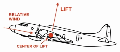
- Many see a lift vector as acting "up;" instead, it acts perpendicular to the aircraft's relative wind and lateral axis. []
- "Up" is, therefore, relative to the aircraft, and turning or even flying upside down in a loop changes the direction of the lift vector points (a fundamental principle in understanding turn performance and aerobatics).
- Lift concentrates from the Center of Lift/Pressure. []
- Note that the center of lift is almost always behind the center of gravity, resulting in a nose-down attitude if not countered by the tail.
- In straight and level flight, the total lift must overcome the aircraft's total weight, comprised of the actual weight and the tail-down force used to control the aircraft's pitch attitude.
- Bernoulli's principle and Newton's Laws of Motion explain lift creation.
-
Bernoulli's Principle:
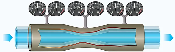
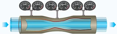
- Bernoulli's principle demonstrates that as the velocity of a moving fluid (liquid or gas) increases, the pressure within the fluid decreases.
- A Venturi demonstrates Bernoulli's principle: A1V1P1 = A2V2P2. []
- A = Area, V = Velocity, and P = Pressure.
- Assuming the area is constant (the wing does not gain or lose surface area), you get V1P1 = V2P2.
- The formula shows that as the velocity of the fluid (air) increases, its pressure must decrease.
- Relating this principle to an airfoil, we see a similar shape.
- The rounded upper surface increases the velocity of the air, which causes pressure to decrease.
- As the pressure above the wing decreases, the relative pressure below it increases, creating a pressure differential, which we know as lift.
- Lift is, therefore, created by decreased pressure, not necessarily by air moving faster over the top.
-
Newton's Laws of Motion:
-
Newton's first law:
"Every object persists in its state of rest or uniform motion in a straight line unless compelled to change that state by forces impressed on it."- A body at rest tends to remain at rest, and a body in motion tends to stay in motion at the same speed and in the same direction.
- Nothing starts or stops moving until some outside force causes it to do so.
- An aircraft at rest on the ramp remains at rest unless a force strong enough to overcome its inertia is applied.
- Two outside forces are always present on an aircraft in flight: gravity and drag.
- The pilot uses pitch and thrust controls to counter or change these forces to maintain the desired flightpath.
- If a pilot reduces power while in straight-and-level flight, the aircraft will slow due to drag.
- However, as the aircraft slows there is a reduction of lift, which causes the aircraft to begin a descent due to gravity.
- Once it is moving, its inertia keeps it moving, subject to the various other forces acting on it.
- These forces may add to its motion, slow it down, or change its direction.
- A body at rest tends to remain at rest, and a body in motion tends to stay in motion at the same speed and in the same direction.
-
Newton's second law:
"Force is equal to the change in momentum per change in time. For a constant mass, force equals mass times acceleration."- When a constant force acts upon a body, its resulting acceleration is inversely proportional to the body's mass and is directly proportional to the applied force.
- It covers both changes in direction and speed, including starting up from rest (positive acceleration) and coming to a stop (negative acceleration or deceleration).
- The equation F(force)=M(mass)A(acceleration) may express this law, where the force is equal to the mass times the acceleration.
-
Newton's Third Law:
"For every action, there is an equal and opposite reaction."- In an airplane, the propeller moves and pushes back the air; consequently, the air pushes the propeller (and thus the aircraft) in the opposite direction (forward).
- This principle applies whenever two things act upon each other. []
- The action of the jet engine's thrust or the pull of the propeller lead to the reaction of the aircraft's forward motion.
- This law is also responsible for a portion of the lift that is produced by a wing, from the downward deflection of the airflow around it.
- This downward force of the relative wind results in an equal but opposite (upward) lifting force created by the airflow over the wing.
-
-
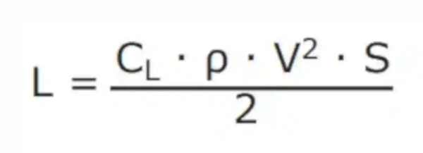
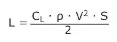
Lift as an Equation:
- The magnitude of the force of lift (L) is directly proportional to the coefficient of lift (CL), the density of the air (ρ), the area of the wings (S), and the velocity (airspeed) (V). []
-
Coefficient of Lift:
- The letters "CL" represent the coefficient of lift in the lift equation.
- The lift coefficient is a numerical value that aerodynamicists use to model the complex relationships between shape, inclination, and certain flow conditions and lift.
-
Air Density:
- The Greek letter rho (ρ) represents air density in the lift equation.
- If air density decreases and the total lift must equal the total weight to remain in flight, another factor must increase.
- The factor usually increased is the airspeed (V) or the Angle of Attack (α) because the pilot controls these directly.
- Several factors, including pressure, temperature, and humidity, influence density.
- At an altitude of 18,000 feet, the air density is one-half the air density at sea level.
- An aircraft must fly at a greater true airspeed for any given AOA to maintain its lift at a higher air density altitude.
- Warm air is less dense than cool air, and moist air is less dense than dry air.
- Thus, on a hot, humid day, an aircraft must be flown at a greater true airspeed for any given AOA than on a cool, dry day.
-
Velocity:
- The letter "V" represents velocity in the lift equation.
- The shape of the wing or rotor cannot be effective unless it continually keeps "attacking" new air.
- If an aircraft is to remain airborne, the lift-producing airfoil must continue to move.
- In a helicopter or gyroplane, the rotation of the rotor blades creates the necessary lift.
- Other aircraft types, such as airplanes, weight shift control, or gliders, require air to move across the lifting surface at a forward speed.
- The forward speed of the aircraft accomplishes this.
- Lift is proportional to the square of the aircraft's velocity, meaning that an airplane traveling at 200 knots has four times the lift as the same airplane traveling at 100 knots if the AOA and other factors remain constant.
-
Wing Area:
- The letter "S" represents the wing area in the lift equation.
- The lift varies directly with the wing area, provided there is no change in the wing's planform.
- If the wings have the same proportion and airfoil sections, a wing with a planform area of 200 square feet lifts twice as much at the same AOA as a wing with an area of 100 square feet.
-
Controlling Lift:
- Pilots control lift primarily through angle of attack and airspeed.
- Flaps can control surface area, but are only used during specific circumstances.
-
Angle of Attack:
- AOA is fundamental to understanding many aspects of airplane performance, stability, and control.
- AOA is often referred to as "alpha" and written with the Greek letter α
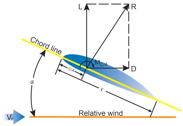
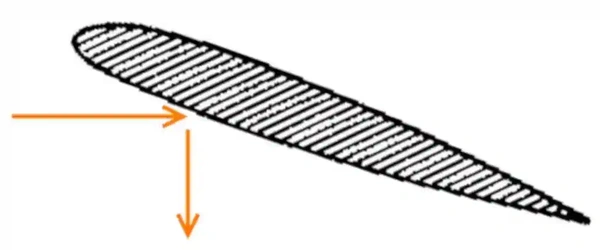
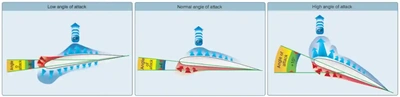
- AOA is the acute angle measured between the relative wind or flight path and the airfoil chord. []
- Relative wind is the direction of the airflow with respect to an airfoil.
- The Angle of Attack, or AOA, changes any time the control yoke or stick moves fore or aft (assuming that is the only change).
- As the AOA increases, lift increases (all other factors being equal).
- When the aircraft reaches the maximum AOA, lift begins to diminish rapidly.
- The maximum AOA is the stalling AOA, also known as "CL-MAX" (maximum CL) or "critical AOA."
- The CL increases until reaching the critical AOA, then decreases rapidly with any further increase in the AOA. []
- Lift created (or reduced in the case of negative AOA) is measured with the coefficient of lift., which relates to the AOA.
- Every airplane has an angle of attack where the maximum lift occurs (stall).
- Other factors that change AOA include weight (higher weight, higher AOA) and speed (slower speed, lower AOA).
- AOA is fundamental to understanding many aspects of airplane performance, stability, and control.
-
Velocity/Airspeed:
- For instance, in straight-and-level flight, cruising along at a constant altitude, altitude is maintained by adjusting lift to match the aircraft's velocity or cruise airspeed while maintaining a state of equilibrium in which lift equals weight.
- In an approach to landing, when the pilot wishes to land as slowly as practical, it is necessary to increase AOA near maximum to maintain lift equal to the aircraft's weight.
- An aircraft cannot continue to travel in level flight at a constant altitude and maintain the same AOA if its velocity increases.
- The lift would increase, and the aircraft would climb due to the increased lift force or acceleration.
- Therefore, lift must be kept constant as velocity increases to keep the aircraft straight and level (not accelerating upward) and in equilibrium.
- Pilots reduce the AOA by lowering the nose to maintain straight and level flight.
- Conversely, as an aircraft slows, the decreasing velocity requires increasing the AOA to maintain sufficient lift to maintain flight.
- There is a limit to how far the AOA can increase to avoid a stall.
- Pilots control lift primarily through angle of attack and airspeed.
-
Lift/Drag Ratio:
- The lift-to-drag ratio (L/D) is the amount of lift generated by a wing or airfoil compared to its drag.
- A L/D ratio is an indication of airfoil efficiency.
- Aircraft with higher L/D ratios are more efficient than those with lower L/D ratios.
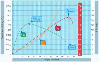
- In unaccelerated flight with steady lift and drag data, pilots can calculate the proportions of the coefficient of lift (CL) and coefficient of drag (CD) for a specific AOA. []
- The lift coefficient is a dimensionless quantity that relates to the lift generated by a lifting body, the dynamic pressure of the fluid flow around the body, and a reference area associated with the body.
- The drag coefficient is dimensionless and used to quantify the drag of an object in a fluid environment, such as air.
- It is always associated with a particular surface area.
- The L/D ratio is determined by dividing the CL by the CD.
- The L/D ratio is equivalent to dividing the lift equation by the drag equation, as all the variables, aside from the coefficients, cancel out.
- The lift and drag equations are as follows (L = Lift in pounds; D = Drag; CL = coefficient of lift; ρ = density (expressed in slugs per cubic feet); V = velocity (in feet per second); q = dynamic pressure per square foot (q = 1⁄2 ρv2); S = the area of the lifting body (in square feet); and CD = ratio of drag pressure to dynamic pressure).
- Typically, the drag coefficient is low at low AOAs, and small changes in AOA only create slight changes in the drag coefficient.
- At high AOA, small changes in the AOA cause significant changes in drag.
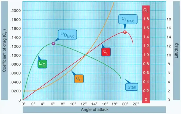
- The shape of an airfoil and changes in the AOA affect the production of lift.
- Notice in [] that the coefficient of lift curve (red) reaches its maximum for this particular wing section at 20° AOA and then rapidly decreases.
- 20° AOA is, therefore, the critical angle of attack.
- The drag curve (orange) coefficient increases rapidly from 14° AOA, overcoming the lift curve at 21° AOA.
- The lift/drag ratio (green) reaches its maximum at 6° AOA, meaning the aircraft produces the most lift for the least drag at this angle.
- Note that the maximum lift/drag ratio (L/DMAX) occurs at one specific CL and AOA.
- If the aircraft operates in steady flight at L/DMAX, the total drag is minimal.
- Any AOA lower or higher than that for L/DMAX reduces the L/D and consequently increases the total drag for a given aircraft's lift.
- [] depicts the L/DMAX by the lowest portion of the blue line labeled "total drag.
- The configuration of an aircraft has a significant effect on the L/D.
-
Airfoil Design:
- Airfoil construction takes advantage of the air's response to Newton's and Bernoulli's principles.
- Air acts in various ways when subjected to different pressures and velocities: a positive pressure lifting action from the air mass below the wing, and a negative pressure lifting action from lowered pressure above the wing.
- If all the lift required were obtained merely from the deflection of air by the wing's lower surface, an aircraft would only need a flat wing like a kite.
- However, the balance of the lift needed to support the aircraft comes from the flow of air above the wing.
- Herein lies the key to flight.
- It is neither accurate nor helpful to assign specific values to the percentage of lift generated by an airfoil's upper surface versus that generated by the lower surface.
- These are not constant values. They vary, not only with flight conditions but also with different wing designs.
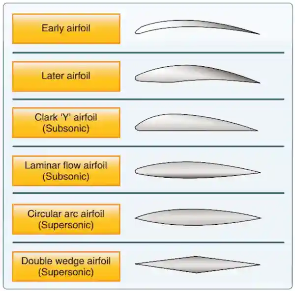
- Different airfoils have different flight characteristics.
- No one airfoil can satisfy every flight requirement.
- Each aircraft's weight, speed, and purpose dictate its airfoil's shape.
- The most efficient airfoil for producing lift is one that has a concave or "scooped out" lower surface.
- As a fixed design, this airfoil type sacrifices too much speed while producing lift and is not suitable for high-speed flight.
- Advancements in engineering have enabled today's high-speed jets to leverage the concave airfoil's high lift characteristics.
- When extended from the basic wing structure, leading-edge (Kreuger) flaps and trailing-edge (Fowler) flaps change the airfoil shape into the classic concave form, thereby generating much greater lift during slow flight conditions.
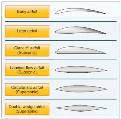
- On the other hand, an airfoil that is perfectly streamlined and offers little wind resistance may not have sufficient lifting power to lift the aircraft off the ground. Thus, modern airplanes have airfoils that strike a balance between extremes in design. The shape varies according to the aircraft's needs.
- [] shows some of the more common airfoil designs.
-
Airfoil Construction:
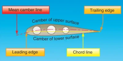
- By looking at the cross-section of a wing, one can see several prominent characteristics of design. [/]
- Notice that there is a difference in the curvatures (called cambers) of the upper and lower surfaces of the airfoil.
- The camber of the upper surface is more pronounced than that of the lower surface, which is usually somewhat flat.
- The two extremities of the airfoil profile also differ in appearance.
- The rounded end, which faces forward in flight, is called the leading edge; the other end, the trailing edge, is relatively narrow and tapered.
-
Chord Line:
- A straight line connecting the extremities of the leading and trailing edges denotes the Chord Line.
- The Chord line is a reference line often used in discussing the airfoil.
- The distance from this chord line to the upper and lower surfaces of the wing denotes the upper and lower magnitude of the camber at any point.
- Another reference line, drawn from the leading edge to the trailing edge, is the mean camber line.
- This "mean line" is equidistant from all points on both the upper and lower surfaces.
- Viewing the wing edgewise, the mean camber connects with the chord line at each end.
-
High Pressure Below:
- Pressure conditions underneath the airfoil generate a certain amount of lift. []
- Because air flows underneath the airfoil, positive pressure results, particularly at higher angles of attack.
- There is another aspect of this airflow to consider:
- At a point close to the leading edge, the airflow nearly comes to a stop (reaching a stagnation point) and then gradually increases in speed.
- At some point near the trailing edge, it again reaches a velocity equal to that on the upper surface.
- In accordance with Bernoulli's principle, slower airflow beneath the surface creates a positive upward pressure (i.e., as fluid speed decreases, pressure increases).
- Since the pressure differential between the upper and lower surfaces of the airfoil increases, total lift increases.
- Pressure conditions underneath the airfoil generate a certain amount of lift. []
-
Low Pressure Above:
- With an airfoil in the shape of a teardrop, the speed and the pressure changes of the air passing over the top and bottom would be the same on both sides. []
- If the airfoil is inclined so that the airflow strikes it at an angle, the air moving over the upper surface moves faster than the air flowing along the bottom.
- This increased velocity reduces the pressure above the airfoil.
- Applying Bernoulli's Principle of Pressure, the increase in airspeed across the top of an airfoil produces a pressure drop. This lowered pressure is a component of total lift. The pressure difference between a wing's upper and lower surfaces alone does not account for the total lift force produced.
- The downward backward flow from the top surface of an airfoil creates a downwash.
- This downwash meets the flow from the bottom of the airfoil at the trailing edge.
- Applying Newton's third law, the reaction of this downward backward flow results in an upward forward force on the airfoil.
- With an airfoil in the shape of a teardrop, the speed and the pressure changes of the air passing over the top and bottom would be the same on both sides. []
-
Pressure Distribution:
- As air flows along the surface of a wing at different AOAs, there are areas along the surface where the pressure is negative or less than atmospheric and regions where the pressure is positive or greater than atmospheric.
- This negative pressure on the upper surface creates a relatively larger force on the wing than is caused by the positive pressure resulting from the air striking the lower wing surface. []
- The average pressure variation for any given AOA is called the center of pressure (CP). The aerodynamic force acts through this CP. At high angles of attack, the CP moves forward, while at low angles of attack, the CP moves aft. In the design of wing structures, this CP travel is essential since it affects the position of the air loads imposed on the wing structure in low and high AOA conditions. Changes in the CP govern an airplane's aerodynamic balance and controllability.
-
Airfoil Behavior:
- Lift production is much more complex than a simple differential pressure between the upper and lower airfoil surfaces. Many lifting airfoils do not have an upper surface longer than the bottom, as in symmetrical airfoils. These are commonly seen in high-speed aircraft with symmetrical wings or in many helicopters, whose upper and lower surfaces are identical, featuring symmetrical rotor blades. In both examples, the only difference is the airfoil's relationship with the oncoming airstream (angle). A paper airplane, which is simply a flat plate, has a distinct bottom and top shape, as well as a defined length. Yet, these airfoils do produce lift, and "flow turning" is partly (or fully) responsible for creating lift.
- As an airfoil moves through the air, it is inclined against the airflow, producing a distinct flow pattern caused by the airfoil's interaction with the oncoming air. Think of a hand placed outside the car window at high speed. If the hand inclines in one direction or another, the hand will move upward or downward. Deflection causes the air to turn about the object within the air stream. The velocity around the object changes in both magnitude and direction, resulting in a measurable velocity force and direction.
-
Wingtip Vortices & Lift:
- While the most significant consideration for producing lift involves the air flowing over and under the wing, there is a third dimension to consider.
- Consider that the tip of the airfoil also has an aerodynamic effect.
- To equalize pressure, the high-pressure area on the bottom of an airfoil pushes around the tip to the low-pressure area on the top. []
- This action creates a rotating flow called a tip vortex or wingtip vortices.
- This downwash extends back to the trailing edge of the airfoil, reducing lift for the affected portion of the airfoil.
- Manufacturers have developed different methods to counteract this action.
- Winglets can be added to the tip of an airfoil to reduce this flow (essentially decrease induced drag).
- The winglets act as a dam, preventing the vortex from forming.
- Winglets can be on the top or bottom of the airfoil.
- Another method of countering the flow is to taper the airfoil tip, reducing the pressure differential and smoothing the airflow around the tip.
- To learn more, see:
-
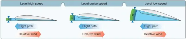
Pitch/Power Relationship:
- An examination of Figure 4-8 illustrates the relationship between pitch and power while controlling flightpath and airspeed. In order to maintain a constant lift, as airspeed is reduced, pitch must be increased. The pilot controls pitch through the elevators, which control the AOA. When back pressure is applied on the elevator control, the tail lowers and the nose rises, thus increasing the wing's AOA and lift. Under most conditions the elevator is placing downward pressure on the tail. This pressure requires energy that is taken from aircraft performance (speed). Therefore, when the CG is closer to the aft portion of the aircraft the elevator downward forces are less. This results in less energy used for downward forces, in turn resulting in more energy applied to aircraft performance.
- Thrust is controlled by using the throttle to establish or maintain desired airspeeds. The most precise method of controlling flightpath is to use pitch control while simultaneously using power (thrust) to control airspeed. In order to maintain a constant lift, a change in pitch requires a change in power, and vice versa.
- If the pilot wants the aircraft to accelerate while maintaining altitude, thrust must be increased to overcome drag. As the aircraft speeds up, lift is increased. To prevent gaining altitude, the pitch angle must be lowered to reduce the AOA and maintain altitude. To decelerate while maintaining altitude, thrust must be decreased to less than the value of drag. As the aircraft slows down, lift is reduced. To prevent losing altitude, the pitch angle must be increased in order to increase the AOA and maintain altitude.


Weight Forces
- Weight is simply the force of gravity on the aircraft, which acts vertically through an aircraft's center of gravity (not center of lift).
- The weight varies based on the combined load of the aircraft, the crew, fuel, and cargo or baggage.
- A load is the back pressure on the control stick required, the G-loading., which an aircraft experiences.
- Passengers and fuel are more obvious.
- Weight generally opposes lift because it exerts a downward force on the aircraft.
- Aerobatics are an exception.
- Weight vs. Lift:
- Weight has a definite relationship to lift.
- Lift is the upward force on the wing acting perpendicular to the relative wind and perpendicular to the aircraft's lateral axis.
- Lift is required to counteract the weight of the aircraft.
- In stabilized level flight, when the lift force is equal to the weight force, the aircraft is in a state of equilibrium and neither accelerates upward nor downward.
- If the lift becomes less than the weight, the vertical speed will decrease.
- When the lift is greater than the weight, the vertical speed will increase.
- To create the lift required to carry the weight comes an increased requirement for thrust to counteract the drag created by the additional lift.
Thrust Forces
- Thrust is the forward-acting force that opposes drag and propels the airplane forward.
- It is through excesses or deficits of thrust that accelerations and decelerations can occur.
- The aircraft will continue to accelerate or decelerate until thrust again equals drag, at which point the airspeed will stabilize.
- In powered aircraft, the powerplant generates thrust, which can be a propeller, rotor, or turbine.
- Gliders create thrust through the conversion of potential energy (altitude) to kinetic energy (airspeed) by pitching toward the ground.
- Newton's second law: When a constant force acts upon a body, its resulting acceleration is inversely proportional to the mass of the body and is directly proportional to the applied force.
- F = MA (Force equals Mass times Acceleration) is an expression of Newton's second law. For example, it applies when speeding up, slowing down, entering climbs or descents, and turning.
- Acts parallel to the center of thrust to overcome drag, F = MA.
- Note that with rotary-wing aircraft, lift and thrust are both in the same direction.
- As a general rule, thrust acts parallel to the longitudinal axis.
-
Measuring Thrust:
- Manufacturers generally rate propeller- and rotor-driven aircraft thrust in horsepower.
- Manufacturers generally rate turbine-driven aircraft thrust in pounds.
-
Thrust During Acceleration:
- Increasing engine power increases thrust (now exceeding drag), thereby accelerating the aircraft.
- As long as the thrust remains greater than the drag, the aircraft continues to accelerate.
- When drag equals thrust, the aircraft flies at a constant speed through the air.
-
Thrust during Deceleration:
- Reducing engine power lessens thrust, thereby decelerating the aircraft.
- As long as the thrust is less than the drag, the aircraft continues to decelerate.
- To a certain extent, as the aircraft slows down, the drag force also decreases.
- The aircraft will continue to slow down until thrust again equals drag, at which point the airspeed will stabilize.
-
Straight-and-level flight:
- The pilot coordinates AOA and thrust in all speed regimes to maintain level flight.
- Remember, (for a given airfoil shape) lift varies with the AOA and airspeed.
- Therefore, a large AOA at low airspeeds produces an equal amount of lift at high airspeeds with a low AOA.
- The speed regimes of flight fall into three categories:
-
Low-Speed Flight:
- When the airspeed is low, the AOA must be relatively high if the balance between lift and weight is to be maintained. []
- If thrust decreases and airspeed decreases, the lift will become less than the weight, and the aircraft will start to descend.
- To maintain level flight, the pilot can increase the AOA by an amount that generates a lift force equal to the weight of the aircraft.
- While the aircraft will be flying more slowly, it will still maintain level flight.
-
Cruising Flight:
- Straight-and-level flight in the slow-speed regime presents some interesting conditions regarding the equilibrium of forces.
- With the aircraft in a nose-high attitude, there is a vertical component of thrust that helps support it. []
- For one thing, wing loading tends to be less than would be expected.
- In level flight, when thrust increases, the aircraft speeds up, and the lift increases.
- The aircraft will climb unless the pilot decreases the AOA just enough to maintain the balance between lift and weight.
- If the AOA decreases too quickly, it will cause the aircraft to descend, and reducing it too slowly will cause the aircraft to climb.
- The opposite is true when thrust decreases in level flight.
-
High-Speed Flight:
- As the airspeed varies due to thrust, the AOA must also vary to maintain level flight.
- At very high speeds and level flight, it is possible to have a slightly negative AOA. []
- As thrust reduces and airspeed decreases, the AOA must increase to maintain altitude.
- If speed decreases enough, the required AOA will increase to the critical AOA.
- Any further increase in the AOA will result in the wing stalling.
- Therefore, extra vigilance is required at reduced thrust settings and low speeds to avoid exceeding the critical angle of attack.
- If equipped with an AOA indicator, it helps monitor the proximity to the critical AOA.
-
- Thrust acts upon the aircraft in relation to the center of gravity.
- If the thrust line is below the center of gravity, the aircraft will tend to pitch up when thrust is increased.
- The inverse is true when thrust is decreased.
- Aircraft like the V-22 and F-35 pivot the engines or vector the exhaust to change the direction of the thrust rather than changing the AOA.

Drag Forces
- Drag is the rearward, resisting force caused by the disruption of airflow.
- Drag is the net aerodynamic force parallel to the relative wind.
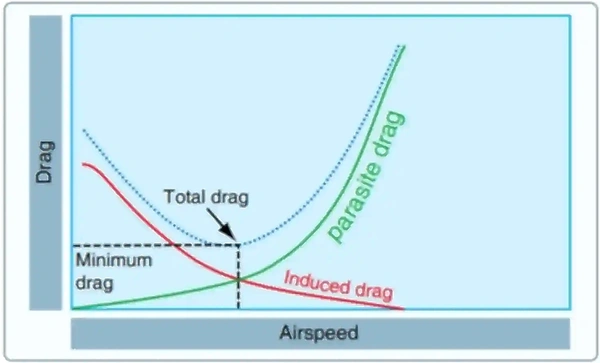
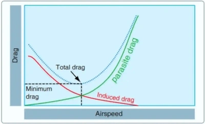
- When induced drag and parasite drag are plotted on a graph, the total drag on the aircraft appears in the form of a "drag curve."
- Drag is always a by-product of lift and thrust.
- There are two basic types of drag (induced and parasite), with total drag being a combination of the two. []
-
Induced Drag:
- In level flight, the aerodynamic properties of a wing or rotor produce a required lift, but this can be obtained only at the expense of a certain penalty.
- That penalty, induced drag, is inherent whenever an airfoil is producing lift.
- Causes wingtip vortices.
- Decreases with airspeed and increases with AOA. []
- Induced drag = 1/V.
- As AOA increases, induced drag increases proportionally.
- To state this another way, the lower the airspeed, the greater the AOA required to produce lift equal to the aircraft's weight and, therefore, the greater the induced drag. The amount of induced drag varies inversely with the square of the airspeed.
-
Wingtip Vortices & Drag:
- An airfoil (wing or rotor blade) produces the lift force by using the energy of the free airstream. Whenever an airfoil produces lift, the pressure on the lower surface is greater than on the upper surface (Bernoulli's Principle). As a result, the air tends to flow from the high-pressure area below the tip upward to the low-pressure area on the upper surface. There is a tendency for these pressures to equalize in the vicinity of the tips, resulting in a lateral flow outward from the underside to the upper surface. This lateral flow imparts a rotational velocity to the air at the tips, creating vortices that trail behind the airfoil.
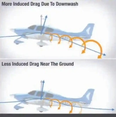
- When viewed from the tail, these vortices circulate counterclockwise around the right tip and clockwise around the left tip. [] As the air (and vortices) roll off the back of your wing, they angle down, known as downwash. [] shows the difference in downwash at altitude versus near the ground. Bearing in mind the direction of rotation of these vortices, they induce an upward flow of air beyond the tip and a downwash flow behind the wing's trailing edge. This induced downwash bears no resemblance to the downwash required to produce lift. It is, in fact, the source of induced drag. Downwash points the relative wind downward, so the more downwash you have, the more your relative wind points downward. That's important for one very good reason: lift is always perpendicular to the relative wind. In , you can see that your lift vector is more vertical, opposing gravity, when you have less downwash. And when you have more downwash, your lift vector points back more, causing induced drag. On top of that, it takes energy for your wings to create downwash and vortices, and that energy creates drag.
- The greater the size and strength of the vortices and the consequent downwash component on the airfoil's net airflow, the greater the induced drag effect becomes. This downwash over the top of the airfoil at the tip has the same effect as bending the lift vector rearward; therefore, the lift is slightly aft of perpendicular to the relative wind, creating a rearward lift component; This is induced drag.
-
Parasite Drag:
- Parasite drag consists of all the forces that work to slow an aircraft's movement.
- As the term parasite implies, it is the drag that is not associated with the production of lift.
- Parasite drag includes air displacement by the aircraft, turbulence generated in the airstream, or a hindrance of air moving over the aircraft's surface and airfoil.
- Parasite drag increases with speed. []
- There are three components of an aircraft's total parasite drag: form drag, interference drag, and skin friction.
-
Profile/Form Drag:
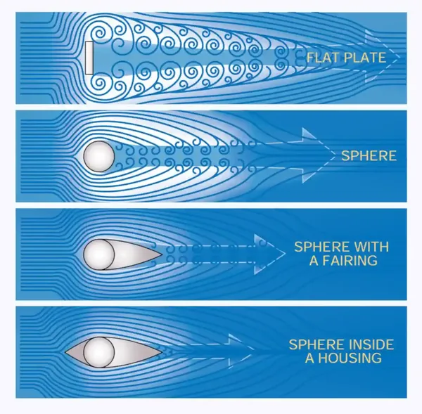
- Form drag is the portion of parasite drag generated by the aircraft and components (antennas, wheels, etc.) due to their shape and airflow around them.
- Turbulent wake results from the separation of airflow (burbling) created by the shape of the aircraft. []
- When the air separates to move around a moving aircraft and its components, it eventually rejoins after passing the body.
- Designers of newer aircraft generally address this by adding fairings along the fuselage to reduce turbulence and form drag. []
-
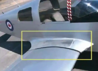
Interference Drag:
- Interference drag is generated by the collision of airstreams, creating eddy currents, turbulence, or restrictions to the smooth flow. []
- For example, at the point where the landing gear meets the fuselage.
- Where two surfaces create the most interference drag is when they meet at perpendicular angles.
- If a jet fighter carries two identical wing tanks, the overall drag is greater than the sum of the individual tanks because both of these generate interference drag.
- Fairings and distance between lifting surfaces and external components (such as radar antennas hung from wings) reduce interference drag.
- Learn more about the effects of interference drag here.
-
Skin Friction Drag:
- Skin friction drag is the aerodynamic resistance caused by the movement of air contacting the surface of an aircraft.
- No matter how smooth, every surface has a rough, ragged surface when viewed under a microscope.
- The air molecules, which come in direct contact with the surface of the wing, are virtually motionless.
- Each layer of molecules above the surface moves slightly faster until the molecules are moving at the velocity of the air mass moving around the aircraft.
- This speed is the free-stream velocity.
- The area between the wing and the free-stream velocity level is about as wide as a playing card and is called the boundary layer.
- At the top of the boundary layer, the molecules increase velocity and move at the same speed as the molecules outside the boundary layer.
- The actual speed at which the molecules move depends upon the shape of the wing, the air's viscosity (stickiness), and its compressibility (how much it can be compacted).
- The airflow outside the boundary layer reacts to the shape of the boundary layer's edge.
- The boundary layer gives any object an "effective" shape that is usually slightly different from the physical shape.
- The boundary layer may also separate from the body, thus creating an effective shape that is significantly different from the physical shape of the object.
- This change in the physical shape of the boundary layer results in a significant decrease in lift and an increase in drag.
- When this happens, the airfoil has stalled.
- To minimize the effect of skin friction drag, aircraft designers employ flush-mount rivets and eliminate any irregularities that may protrude above the wing surface.
- Additionally, a smooth and glossy finish facilitates the smooth transition of air across the wing's surface.
- Since dirt on an aircraft disrupts the free flow of air and increases drag, keep its surfaces clean and waxed.
- Skin friction drag is the aerodynamic resistance caused by the movement of air contacting the surface of an aircraft.
- Pilots can intentionally create drag using speed/dive brakes or spoilers.
- Additionally, normal procedures such as lowering flaps can increase drag.
- Parasite drag increases as the square of the airspeed (V^2).
- Thus, as airspeed decreases to near the stalling speed in a steady state, the total drag becomes greater due mainly to the exponential rise in induced drag. Similarly, as the aircraft reaches its never-exceed speed (VNE), the total drag increases rapidly due to the sharp increase in parasite drag.
- Parasite drag consists of all the forces that work to slow an aircraft's movement.
- Understanding the drag curve can provide valuable insight into the various performance parameters and limitations of the aircraft.
- Because power must equal drag to maintain a steady airspeed, the curve can be either a drag curve or a power required curve. The power required curve represents the amount of power needed to overcome drag in order to maintain a steady speed in level flight.
- The propellers used on most reciprocating engines achieve peak propeller efficiencies in the range of 80 to 88 percent. As airspeed increases, the propeller efficiency increases until it reaches its maximum. Any airspeed above this maximum point causes a reduction in propeller efficiency. An engine that produces 160 horsepower will have only about 80 percent of that power converted into available horsepower, approximately 128 horsepower. The remainder is lost energy. This is the reason the thrust and power available curves change with speed.


Interaction Between the Four Forces of Flight
- The four forces of flight do not exist in isolation, as each influences the other.
- Lift opposing weight and drag opposing thrust are only valid in level flight.
- For example, a pitch-up requires thrust to overcome drag and weight.
- All other factors being constant, for every AOA, there is a corresponding airspeed required to maintain altitude in steady, unaccelerated flight (valid only if maintaining level flight).
- Since an airfoil always stalls at the same AOA, the lift must increase if the weight increases.
- The only method of increasing lift is by increasing velocity if the AOA is held constant just short of the "critical," or stalling, AOA (assuming no flaps or other high lift devices).
- Lift and drag also vary directly with the density of the air.
-
Initiating and Establishing a Climb:
- When a pilot initiates a climb, power (not thrust) is increased (simultaneously increasing lift and drag).
- As the pilot pitches up, lift (AOA) is increased.
- As lift increases drag is increased and the weight vector moves aft, complementing drag.
- Eventually the aircraft reaches an equilibrium between weight + drag and lift; the aircraft is in a steady-state climb.
- Note that the excess power results in establishing the best rate of climb while excess thrust (the byproduct of power in a propeller driven aircraft) results in establishing the best angle of climb.
- When a pilot initiates a climb, power (not thrust) is increased (simultaneously increasing lift and drag).
-
Initiating and Establishing a Descent:
- When a pilot initiates a descent, thrust is decreased (simultaneously decreasing lift and drag).
- As the pilot pitches down, lift (AOA) is decreased.
- As lift decreases drag is decreased and the weight vector moves forward, complementing thrust.
- Eventually the aircraft reaches an equilibrium between weight + thrust and lift; the aircraft is in a steady-state descent.
- When a pilot initiates a descent, thrust is decreased (simultaneously decreasing lift and drag).
-
Ground Effect:
- Ground effect is the reduction of induced drag during takeoffs and landings, allowing the aircraft to fly at lower than expected airspeeds.
- The effect is caused by a reduction of wingtip vortices which decreases induced drag.
- Note the opposite is true when leaving ground effect, causing a decrease in stability and nose-up moments.
- Aircraft experience ground effect at about a wingspan above the ground.
- Upwash and downwash. decrease.
- As an aircraft climbs out of ground effect, drag increases, sometimes to a degree that requires a decrease in pitch attitude to maintain climb airspeed.
- Downwash can hit the ground and push the wing from below, forming what feels like a cushion.
- Causes floating if fast on approach.
- More noticeable in a low-wing aircraft.
-
Rotary-Wing Considerations:
- Concerning rotary-wing aircraft, lift and thrust are in the same direction.
Principles of Flight Knowledge Check
Private Pilot
Core Knowledge Review
Review the foundational knowledge, key concepts, and practical considerations for Principles of Flight.
Foundational
Immediate Feedback
Answer Explanations
Commercial Pilot
Advanced Application
Apply your knowledge of Principles of Flight to advanced operational scenarios, risk management, and aeronautical decision-making.
Advanced
Scenario Based
Risk Management
Why Take a Quiz?
Quizzes reinforce key concepts, identify knowledge gaps, and build confidence for real-world decisions in the cockpit.
The Principles of Flight Conclusion
- The principles of flight refer to the fundamental characteristics that govern an aircraft.
- Although simplified as thrust, lift, weight, and drag, we know that there are more upward forces than lift and more downward forces than just weight.
- Although the pilot can only control some of these factors, the lift available is affected by wing design, angle of attack, velocity, weight and loading, air temperature, and humidity.
- Bernoulli's Principle and Newton's Laws apply whenever an airfoil generates lift.
- You can see that the four forces of flight are interrelated.
- To achieve flight, we must overcome drag and resist the force of gravity.
- To maintain a constant airspeed, thrust and drag must remain equal, just as lift and weight must be equal to maintain a constant altitude.
- AOA drives lift as the pilot effectively controls the distribution of pressures above and below the airfoil.
- Although AOA and velocity allow a pilot to manipulate lift, other factors are slightly under the pilot's control, such as air density (as a pilot can change altitude).
- Several books are available in digital and hard copy to help you learn more [Amazon].
- In unaccelerated, level flight, the four forces are in equilibrium.
- Equilibrium is when lift equals down-force (weight and tail downforces [which make up ~5% of aircraft weight]) and thrust equals drag, but by changing these forces, we can affect climbs, descents, and other maneuvers.
- To learn more, consider AOPA's Essential Aerodynamics online course.
- Check out the FAA's Angle of Attack fact sheet for more information about AOA.
- See also:
- Aircraft design and how the four forces of flight interact drive weight & balance requirements and limitations.
- A balanced aircraft is a happy aircraft (fuel burn, efficiency, etc.).
- As discussed, lift generation is not without its drawbacks, necessitating an understanding of wake turbulence and its risks, especially in the terminal environment.
- Rotor Blade: spinning "wings" which allow for lift on helicopters or "rotor-craft."
- Stabilizer: a control surface other than the wings that provides stabilizing qualities.
- Chord: Chord line longitudinal length (length as viewed from the side).
- Chord Line: The chord line is the straight line intersecting the leading and trailing edges of the airfoil.
- Angle of Incidence (AoI): the angle between the airfoil chord and the aircraft's longitudinal axis into the aircraft, and the pilot cannot change it.
- Attitude: the relationship of the aircraft's nose with the horizon.
- Flight Path: The course or track along which the aircraft is or intends to fly.
- Lift: A component of the total aerodynamic force on an airfoil that acts perpendicular to the relative wind.
- Center of Gravity: The average weight across an aircraft through which gravity "acts."
- Weight: Opposes lift via gravity.
- Thrust: Forward force that propels the airplane.
- Drag: Retarding force that limits speed.
- Still looking for something? Continue searching:
The Principles of Flight References
- Aircraft Owners and Pilots Association - Aerodynamics.
- Aircraft Owners and Pilots - Aerodynamics Resources.
- Aircraft Owners and Pilots Association - Aircraft Maintenance: Tips for Prop Tracking.
- Airplane Flying Handbook.
- Federal Aviation Administration - Instrument Flying Handbook (2-2) Review of Basic Aerodynamics.
- Federal Aviation Administration - Pilot/Controller Glossary.
- Federal Aviation Administration - Safety Team: Angle of Attack Awareness.