Stall Performance
Stalls are an aerodynamic condition whereby air can no longer smoothly flow over an airfoil, resulting in a rapid loss of lift.
Introduction to Stall Performance
- Stalls are an aerodynamic condition whereby air can no longer smoothly flow over an airfoil, resulting in a rapid loss of lift.
- Stalls are ultimately brought on by exceeding the critical angle of attack.
- A stall is, therefore, an aerodynamic condition in which the Angle of Attack (AOA) becomes so steep that air can no longer flow smoothly over the airfoil.
- Said another way, a stall is a condition of flight in which an increase in AOA results in a decrease in lift.
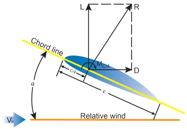
- Angle of Attack (AOA/Alpha): the angle between the relative wind and the chord line of an airfoil.
- Critical AOA: the angle of attack whereby any further increase will result in a separation of airflow, which results in a stall.
- An airfoil's ability to provide sufficient lift is dependent upon the load factor, that is, the amount of lift required to support the aircraft's load in flight.
- Load factor is not only dependent on the aircraft's weight, but also on the angle of bank, which contributes to the effective weight of the aircraft.
- Upon airflow separation from the wing, the airfoil will no longer produce lift.
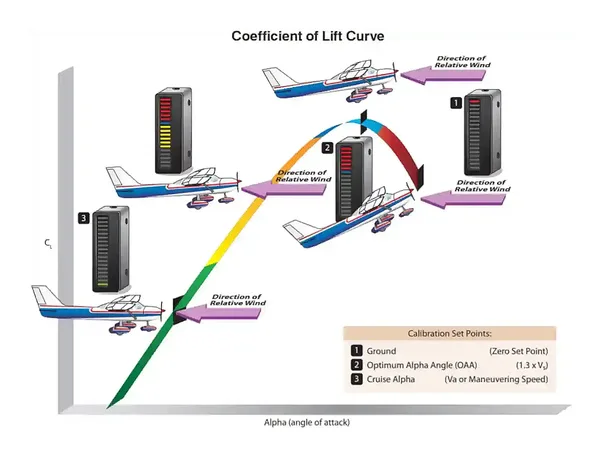
- Pilots and engineers measure the angle of attack using relative or normalized units rather than degrees.
- Approaching the critical angle of attack, several indications of a stall will be present, warning pilots of pending danger.
- Although it is an abstract concept expressed in abstract units, several stall speed considerations are taken into account in aircraft design and performance envelopes to keep the aircraft within the normal flight envelope, enabling stall recognition before it's too late.
- Still, stall avoidance practices are critical.
- Notably, compressor stalls result from the same airfoil stall principles.
- Still, they are specific to turbine aircraft and generally not a factor when aircraft operate inside their normal flight envelope.
Stall Performance Key Highlights
- A stall occurs when the wing exceeds its critical angle of attack and can no longer produce sufficient lift.
- Stalls can occur at any airspeed, attitude, or power setting if the critical angle of attack is exceeded.
- Aircraft weight, load factor, configuration, and center of gravity influence stall characteristics and stall speed.
- Increased load factor during turns and maneuvers raises stall speed and reduces available performance margins.
- Flap deployment generally lowers stall speed by increasing wing lift at slower airspeeds.
- Turbulence, icing, and contamination on the wing surface can alter airflow and degrade stall performance.
- Approaching stalls are commonly indicated by aerodynamic buffet, decreased control effectiveness, and stall warning systems.
- Proper stall recovery requires reducing the angle of attack and applying appropriate power and coordinated control inputs.
- Uncoordinated stalls can develop into spins if yaw is present during the stall condition.
- Understanding stall performance improves aircraft control, maneuvering safety, and aeronautical decision-making.
Defining Aircraft Stalls
- Stalls evoke images of an engine turning off, like in a car with mechanical trouble.
- In aviation, however, a stall is an aerodynamic condition that occurs when smooth airflow over the airplane's wings gets disrupted, resulting in a loss of lift.
- The loss of lift causes the wing to stop producing sufficient lift.
- While the concept of a stall sounds like a terrifying experience, it is predictable and therefore a subject of training syllabi to identify risk factors, recognize its occurrence, and perform corrective actions to return the airfoil to its normal flight condition.
Effects of Angle of Attack on Stall Performance
- The angle of attack is fundamental to understanding many aspects of airplane performance, stability, and control.
- AOA is the acute angle measured between the relative wind or flight path and the chord of the airfoil. []
- Flight Path: Path described by its center of gravity as it moves through an air mass.
- Relative Wind: The airflow the airplane experiences as it moves through the air.
- Angle of Incidence: The chord line of the wing is angled up when attached to the fuselage.
- Pitch Attitude: Angle between an airplane's longitudinal axis and the horizon.
- Equal in magnitude and opposite in direction to the flight path.
- Do not infer flightpath, relative wind, or angle of attack from pitch attitude.
- Whenever the control yoke or stick moves forward or aft, the AOA changes.
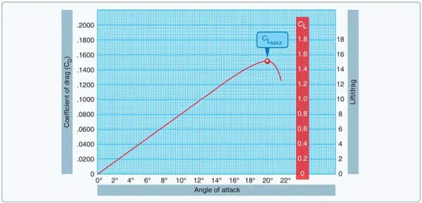
- As the AOA increases, lift increases (all other factors being equal).
- When the aircraft reaches the maximum AOA, lift begins to diminish rapidly.
- The rapid diminishment of lift is the stalling AOA, known as the maximum critical lift ("CL-MAX") or the critical AOA.
- The CL increases until reaching the critical AOA, then decreases rapidly with any further increase in the AOA. [/]
- Engineers measure the lift created (or reduced in the case of negative AOA) with the coefficient of lift, which relates to the AOA.
- Every airplane has a specific angle of attack at which maximum lift occurs, known as the critical angle of attack.
- The critical angle of attack is that angle at which, regardless of airspeed, flight attitude, or weight, the airfoil will stall.
- Factors like weight, altitude, and airspeed impact AOA required to maintain flight, but the critical AOA remains the same since the airfoil remains the same (i.e. these factors impact margin).
- With an understanding that the angle of attack is the wing's relative "bite" of the air, this can put airflow principles into perspective.

Effects of Airflow/Airspeed on Stall Performance
- To better understand how air flows over a wing, you must first understand its characteristics.
- Airflow layers can be either laminar or turbulent.
-
Boundary-Layer:
- The boundary layer is the layer of airflow over a surface that demonstrates local airflow retarding due to viscosity (as it gives up kinetic energy to friction).
- The air molecules in the boundary layer (surface layer) remain stationary relative to the surface; however, the layer above them moves over the stagnant molecules because a third layer near the free stream pulls it along.
- The velocities of the layers increase as the distance from the surface increases, until they reach the free stream velocity.
- The total distance between the aircraft surface and the free stream velocity is the boundary layer.
- At subsonic levels, the cumulative layers are about the thickness of a playing card, increasing in thickness as they move aft.
- When air flows across any surface, friction develops.
- As a viscous fluid resists flow or shearing, the adjacent layer of air slows.
- Succeeding streamlines slow down less until eventually, some outer streamline reaches the free airstream velocity.
-
Laminar Flow:
- The air moves smoothly along in a streamline.
-
Turbulent Flow:
- Streamlines that break up, causing the flow to be disorganized and irregular.
- Produces higher friction than laminar.
- Adheres more effectively to the surface of the airflow, thereby delaying separation.
- Traction pads and even bugs can disrupt laminar flow, affecting aircraft performance.
-
Pressure Gradients:
-
Favorable Pressure Gradient:
- A Favorable Pressure Gradient (FPG) helps the boundary layer adhere to the surface by maintaining its high kinetic energy.
- As air flows aft from the point of maximum thickness toward the trailing edge (low to high static pressure), it encounters an adverse pressure gradient.
-
Adverse Pressure Gradient:
- An Adverse Pressure Gradient (APG) impedes the flow of the boundary layer.
- Strongest during high lift conditions and at high AOAs, in particular.
- If the boundary layer does not have sufficient kinetic energy to overcome the APG, then the lower levels of the boundary layer will stagnate and separate as airflow reverses.
- As separation progresses toward the leading edge of the wing, the net suction decreases, and CL decreases, resulting in a stall.
- Even at low angles of attack, there will be a small APG behind the point of maximum thickness.
- As the separation progresses forward toward the leading edge of the wing with increasing AOA, eventually, the air cannot conform to the sharp turn.
-
-
Airspeed:
- As airspeed increases, airflow generally becomes more laminar, which helps maintain FPG.
- As airspeed decreases (AOA increases), airflow generally begins to separate, becoming turbulent, which creates a phenomenon known as APG.
- Higher airspeeds also reduce the angle of attack required, increasing stall margin.
- The high angle of attack at low airspeeds most commonly results in stall conditions.
- Recall aircraft can exceed the critical angle of attack at any airspeed.
- Indiated stall speed remains constant as density altitude increases because the airspeed indicator measures dynamic pressure (i.e., it self-corrects based on the conditions).
Effects of Load Factor on Stall Performance
- Load factor is the weight the wings are supporting. []
- Load factor is generally not calculated as part of preflight; however, it has a close relation to stall speed, which is very important.
- As the load factor increases, the stall speed increases.
- In level flight, the load factor is the ratio of the aircraft's weight to its lift.
- The aircraft is experiencing a "1-g" load factor or 1 times the force of gravity.
- As you increase the angle of bank, however, a pilot must pull back on the controls to avoid descending.
- This is due to the loss of vertical lift, which then raises the load factor.
-
Calculating Load Factor:
- Pilots will generally rely on the 60° angle of bank as a 2-Gs rule of thumb; performance charts use the technical data considered.
- Still, pilots can be more precise if they choose to use some relatively simple math.
-
Load Factor Formula:
- Load Factor Formula: Load Factor = 1 / cos(angle of bank).
-
Load Factor Calculation Example:
- Conditions: Given an angle of bank of 60°.
- Load Factor = 1 / cos(60).
- Load Factor = 1 / 0.5.
- Load Factor = 2.
-
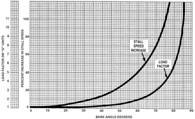
Load Factor Chart Example:
- Start with the 60° mark at the bottom of the chart and move up until you intercept the load factor reference line. []
- Move over to the left and see the load factor imposed on the aircraft.
- You should come up to approximately 2.
- Pilots will generally rely on the 60° angle of bank as a 2-Gs rule of thumb; performance charts use the technical data considered.

Effects of Angle of Bank on Stall Performance
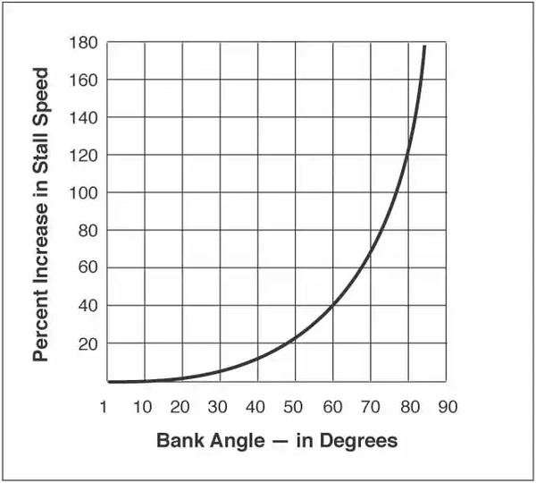
- As mentioned above, stall speed increases exponentially with load factor due to a loss in the vertical component of lift.
- This is the principle behind accelerated stalls.
- Increasing the bank angle increases the load factor, which in turn increases the stall speed. []
- Correspondingly, decreasing the bank angle decreases the load factor, which in turn decreases the stall speed.
-
Calculating Stall Speed:
-
Stall Speed Banked Formula:
- Stall Speed Banked = [Stall Speed Level x Square Root of Load Factor].
Conditions:
- Given an aircraft with a stall speed of 48 knots with a load factor of 2 (60° angle of bank).
Calculation:
- Stall speed banked = [Stall Speed level x Square Root of Load Factor].
- Square root of 2 = 1.41.
- Stall speed banked = 48 x 1.41.
- Stall speed banked = 68 KIAS.
Chart:
[]- Look at the 60° mark at the bottom of the chart and move up until you intercept the stall speed increase reference line.
- Move over to the left and see the percent increase in stall speed.
- You should come up with an increase in stall speed of approximately 41%
- Stall Speed Banked = [Stall Speed Level x percent increase in stall speed].
- Stall Speed Banked = 48 x 1.41.
- Stall Speed Banked = 68 KIAS.
- You should come up with an increase in stall speed of approximately 41%
-
Effects of Power on Stall Performance
- Stall practice is necessary to recognize when the aircraft is behind the power curve (sometimes referred to as a region of reverse command) and to learn how to recover successfully.
- The aircraft is said to be operating behind the power curve whenever it is flying below the best endurance speed.
- Best endurance is the minimum power required to maintain level flight, which typically occurs in Cessna 172s at about 60 knots.
- In normal flight, pitch controls altitude, and power controls airspeed.
- When operating in the region of reverse command, the controls reverse, with pitch controlling airspeed and power controlling altitude.
- Said differently, when behind the power curve, more power is required to overcome drag.
- Pilots will operate both behind and ahead of the power curve throughout the flight, with the most critical terminal phases of takeoff and landing occurring when the aircraft is behind the power curve.
Effects of Weight/Center of Gravity on Stall Performance
- Control surfaces stall because they exceed their angle of attack.
- Pilots increase angles of attack to support the flight conditions, the most basic of which is weight.
- As weight increases, stall speed increases, as more lift is required to maintain level flight.
- Correspondingly, as weight decreases, less weight is required to maintain level flight, resulting in a decrease in stall speed.
- The center of gravity indirectly affects how an aircraft stalls and its performance.
- As the center of gravity moves forward, the aircraft must increase lift, and therefore, the stall speed increases.
- Correspondingly, as the center of gravity moves aft, less downforce is required, and stall speed decreases.
- If an aircraft stalls for a forward CG, it is easier to recover because the nose will tend to drop.
- An aircraft with an aft CG will tend not to drop the nose, and therefore, stall recovery will be delayed (more altitude lost).
- Weight and balance calculations performed during preflight planning indirectly inform stall performance by providing pilots with an expectation of how the aircraft will behave.
Effects of Coordinated Flight on Stall Performance
-
Stalls in Coordinated Flight:
- If the coordination of the turn at the time of the stall is accurate, the airplane's nose will pitch away from the pilot just as it does in a straight flight stall.
-
Stalls in Uncoordinated Flight:
- If the airplane is slipping toward the inside of the turn at the time of the stall, it tends to roll rapidly toward the outside of the turn as the nose pitches down, because the outside wing stalls before the inside wing.
- If the airplane is skidding toward the outside of the turn, it will tend to roll to the inside of the turn because the inside wing stalls first.
- Stalling will occur at a higher airspeed, resulting in a lower-than-expected pitch and a quick, unexpected stall.
- If the aircraft becomes uncoordinated while turning, one wing may suddenly drop, causing the airplane to roll in that direction. If this occurs, the excess back-elevator pressure must be released, power added, and the aircraft returned to straight-and-level flight with coordinated control pressure.
- Note that in a slip, the outside wing is experiencing slower movement through the air, resulting in a higher angle of attack to maintain lift.
- In the event of a stall, the aircraft will then roll to the outside wing (due to a higher angle of attack causing the initial stall).
- The reverse is true for a skid, where the inside wing drops first due to the relatively slower movement through the air.
Effects of Stall Speed on Stall Performance
- As AOA increases up to CL MAX AOA, True Airspeed (TAS) decreases to a point where it cannot be any slower than stall speed (Vs).
- Airspeeds may change based on weight and configuration, but units of AOA remain the same.
- You can stall at any airspeed.
- Going too slow causes high AOA, while going too fast causes shock waves on aircraft not designed for supersonic or even transonic flight, causing the same disruption as high AOA.
-
Weight:
- As weight decreases, so does stall speed, as less lift is required.
- Dropping a payload or just using fuel decreases stall speed and, thus, approach speed (AOA approaches).
-
Altitude:
- Higher altitude results in fewer air molecules, so a higher TAS is required; however, indicated airspeed remains the same.
- Increased altitude results in increased stall speed.
-
Angle of Bank:
- As you increase your angle of bank, stall speed increases due to the decreased vertical component of lift. []
- To compensate, the pilot raises the angle of attack to produce more lift until the aircraft stalls (at a lower speed).
- See turns.
-
Power Off/On:
- Power-on conditions will have lower stall speeds because lift generation is supported by the vertical component of thrust.
- Additionally, with the power, you will induce airflow over the wings.
Effects of Aircraft Design on Stall Performance
-
Wing Tailoring:
- Wing tailoring makes stalling characteristics more predictable by attempting to stall the root first.
- Power-on stalls may tend to stall at the tip first due to induced lift.
- With the wings stalling at the root first, the aircraft maintains some aileron authority.
-
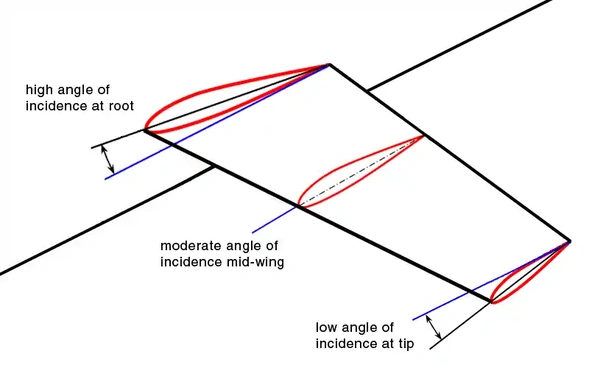
Geometric Twist/Washout:
- A decrease in the angle of incidence from the wing root to the wingtip. []
- The wing gradually twists downward, decreasing its AOA.
- A decrease in the angle of incidence from the wing root to the wingtip. []
-
Aerodynamic Twist (Section Variation):
- A gradual change in airfoil shape results in a decrease in camber from root to tip and/or by reducing the chord.
-
Stall Fences:
- Redirect the airflow along the chord.
- Allows the wing to achieve a higher AOA without stalling (delaying tip stall).
-
Vortex Generators:
- Vortex generators enhance turbulent flow over the wings, thereby delaying the separation of the flow.
-
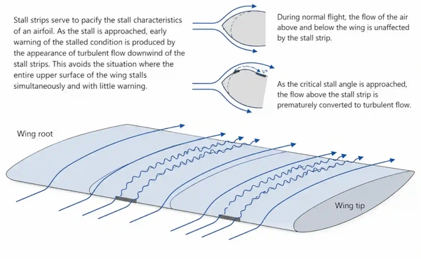
Stall Strips:
- A sharply angled piece of metal at the root section to induce a stall at the root. []
- Subsonic airflow cannot follow sharp contour changes.
-
Flaps/Slats:
- Lowering flaps decreases stall speed and increases drag.
- Raising flaps increases stall speed back to Vs speed while also decreasing drag.
- Consider the impacts of configuration changes (and, more importantly, the stall speed) when in a low, slow, and potentially go-around situation.
- The same principle applies to flaps as to slats, although slat deployment is generally automatic.

Effects of Icing on Stall Performance
- Stalls due to icing are particularly insidious, as the indications may not be present or may be entirely different from those of other causes.
- Icing causes the aircraft to stall at a lower-than-normal angle of attack, potentially before the pilot can recognize an abnormal condition.
- Icing-related stalls may not have an accompanying stall horn due to the frozen position of the indicator or because the aircraft could stall at a lower-than-normal angle of attack.
- Stall speed may increase by as much as 20 knots.
- Pilots may experience lightness in the controls, difficulty trimming, or PIO.
- FAA Notice (8900.267) Focused Review of Flightcrew Member Training for Ice-Contaminated Tailplane Stall or on the Type Certificate Data Sheet (TCDS) provides aircraft certification information (if certified).
- Slow usually indicates wing stall, whereas fast usually indicates tail stall.
Approaches to Stalls Maneuvers
- Select an altitude where recovery will occur no lower than 1500' AGL.
- Commence a clearing turn.
- While maintaining heading, reduce power, and adjust pitch (trim) to maintain altitude.
- For Dirty Configuration:
- Advance the propeller control to full forward (high rpm) as required.
- While maintaining altitude, slowly establish the pitch attitude, power setting, and, if applicable, bank (15-30°) that would induce a stall.
- At the first indication of an impending stall, calling "stalling" and initiate recovery, maintaining heading while smoothly and continuously increasing power to full and adjusting pitch to maintain altitude (trim).
- For Dirty Configuration:
- Right rudder will be necessary to counteract the increase in p-factor.
- As airspeed increases, raise the flaps in increments to 10°:
- An overly abrupt flap retraction will result in a dramatic loss of lift and possibly a stall.
- As airspeed increases, but remains below VLO, raise the landing gear.
- At or above Vx, retract flaps to 0°.
- Approaching cruise airspeed, set cruise power.
- Re-trim as necessary.
- Complete the Cruise Flow/Checklist.
Stall Recognition
-
Feel:
- The pilot will feel control pressures change as speed reduces.
- With progressively less resistance on the control surfaces, the pilot must use larger control movements to get the desired airplane response.
- The pilot will notice that the airplane's reaction time to control movement increases.
- Just before the stall occurs, buffeting, uncommanded rolling, or vibrations may begin to occur.
- If installed, rudder pedals or stick shakers will engage leading up to a stall.
- The pilot will feel control pressures change as speed reduces.
-
Vision:
- Since aircraft can stall in any attitude, vision is not a foolproof indicator of an impending stall.
- However, maintaining pitch awareness is essential.
- If installed, warning lights will illuminate before a stall occurs.
- Since aircraft can stall in any attitude, vision is not a foolproof indicator of an impending stall.
-
Hearing:
- As speed decreases, the pilot should notice a change in the sound made by the air flowing along the airplane's structure.
- If installed, horns or buzzers will sound to alert the pilot to a stall.
-
Kinesthesia:
- The physical sensation (sometimes referred to as "seat of the pants" sensations) of changes in direction or speed is an essential indicator to the trained and experienced pilot in visual flight.
- This sensitivity can warn the pilot of an impending stall.
- The physical sensation (sometimes referred to as "seat of the pants" sensations) of changes in direction or speed is an essential indicator to the trained and experienced pilot in visual flight.
Stall Recovery Fundamentals
- Stall recoveries are fundamentally the same if you remember "Max - Relax - Level."
- Apply maximum power (increases lift).
- Relax the nose (decreases the angle of attack).
- Level the wings (reduces the stall velocity to allow all available lift to break the descent).
- See power-off stalls, power-on stalls, elevator trim stalls, cross-controlled stalls, accelerated stalls, and secondary stalls.
Stall Avoidance
- Avoid flying at minimum airspeeds.
- Remain in the normal flight envelope.
- Avoid abrupt maneuvers.
Compressor Stalls
- Compressor stalls, while related in their cause, have nothing to do with the wing.
- To learn more about compressor stalls, visit the Powerplant page.
Common Training Aircraft Stall Warning System Characteristics
-
Piper Arrow:
- Activated by a lift detector on the left wing.
- Activates 5 to 10 knots before stall.
- The warning horn sounds at 90Hz.

Stall Performance Knowledge Check


Stall Performance Conclusion
- Understanding stalls is fundamental to safe aircraft control and loss-of-control prevention.
- Stalls are dependent on AOA only, and the only way to recover is to reduce the AOA.
- Pilots without an AOA indicator often reference stall speeds, which are affected by weight, center of gravity, and bank angle/load factor.
- A stall can occur at any pitch attitude or airspeed, despite common discussions regarding stall "speed".
- To learn more, check out Stalls, Spins, and Safety.
- To learn more about stalls and airflow, check out NASA's FOILSIM III.
- Still looking for something? Continue searching:
Stall Performance References
- Federal Aviation Administration - Notice (8900.267) Focused Review of Flightcrew Member Training for Ice-Contaminated Tailplane Stall.
- Federal Aviation Administration - FAASTeam: Stall, Spin, and Upset Recovery Training.
- Federal Aviation Administration - Pilot/Controller Glossary.
- NASA - FOILSIM III.