Thermal Soaring
Thermal Soaring is the use of rising air to climb, reduce altitude loss, or otherwise remain airborne without engine power.
Introduction to Thermal Soaring
- Thermal soaring uses convective rising air to maintain or gain altitude. The pilot continually adjusts the circle to remain in the strongest usable lift while maintaining safe airspeed, bank, stall margin, lookout, and landing options.
- When the climb weakens on part of the circle, the pilot uses coordinated corrections to shift the circle toward stronger lift. A steeper bank is not automatically better because it increases stall speed and the glider's sink rate.
- Weather analysis may include atmospheric sounding or forecast products, but no single chart replaces observation of actual lift, wind, clouds, convection, terrain, traffic, and available landing areas.
- Reinforce your understanding of Thermal Soaring by completing the knowledge quiz and interactive scenario, comparing your performance with the applicable Airman Certification Standards, and reviewing the topic summary before moving on.
Thermal Soaring Key Highlights
- Thermal soaring uses rising columns of warm air to gain altitude and extend glider or aircraft flight duration without engine power.
- Thermals form when uneven surface heating causes warm air to rise through cooler surrounding air.
- Dark terrain, paved surfaces, rocky areas, and plowed fields commonly generate stronger thermals during daylight heating conditions.
- Cumulus clouds often indicate the presence of thermals and rising air beneath the cloud formation.
- Pilots typically circle within thermals to remain inside the strongest areas of rising air.
- Variometers help pilots identify rising and sinking air by measuring changes in vertical speed.
- Thermal strength, turbulence, and drift are influenced by wind conditions, atmospheric stability, and surface heating intensity.
- Glider pilots must balance climb performance, airspeed selection, and thermal centering techniques during soaring operations.
- Sink areas between thermals require pilots to manage altitude, glide performance, and route planning carefully.
- Understanding thermal soaring improves energy management, atmospheric awareness, and soaring flight efficiency.
Locating Thermals
- Thermals can be located by looking for cues in the environment
-
Clouds:
- Cumulus clouds in their early building stages indicate rising warm air that is cooling enough for condensation to form a cloud.
-
Birds:
- Sometimes birds can be an indication of rising air
-
Other Gliders:
- Pay attention to what other glider pilots are doing
-
Wind:
- Probable thermals will be pushed in the direction of the wind
Soaring Forecast
- Soaring forecasts provide insight as to the conditions you can expect
- Published by a local National Oceanic and Atmospheric Administration (NOAA) office
- The best way to find soaring forecasts is to type into any search engine your airport or region followed by soaring forecast
- Example: Warner Springs soaring forecast
- The best way to find soaring forecasts is to type into any search engine your airport or region followed by soaring forecast
Thermal Updraft Velocity
- Forecasts the upward velocity of air within the thermal and will never be negative
- The glider descent rate while thermalling must be subtracted to give the expected variometer reading
- Find more here.
Buoyancy/Shear Ratio
- A small Buoyancy/Shear (B/S) ratio indicates that wind shear is strong relative to thermal buoyancy.
- A B/S of 5 or less means thermals are likely to be broken to unusable
- A B/S of 10 or higher means shear is unlikely
- Find more here.
Boundary Layer Top
- The boundary layer top is the height of the "mixing layer" where surface turbulence mixes with the atmosphere above it
- The height where the dry adiabatic lapse rate through surface temperature intersects the temperature profile
- Essentially where TI=0
- Find more here.
Boundary Layer Max Up/Down Motion
- Maximum grid-area-averaged extensive upward or downward motion within the boundary layer as created by horizontal wind convergence
- Positive convergence is associated with local small-scale convergences lines (shear lines)
- Negative convergences (divergence) produces subsiding vertical motion, creating low-level inversions which limit thermalling heights
- Find more here.
Boundary-Layer Wind Speed
- Boundary-layer wind speed is the average wind speed and direction within the convective boundary layer.
- Stronger boundary-layer winds can organize thermals into streets, but they can also increase drift and make returning upwind more difficult.
- Learn more about boundary-layer forecasts and soaring conditions.
Cu Cloudbase
- Plotted where cloud bases are theoretically expected
- Find more here.
Flight Hazards Exist Around Exhaust Plumes
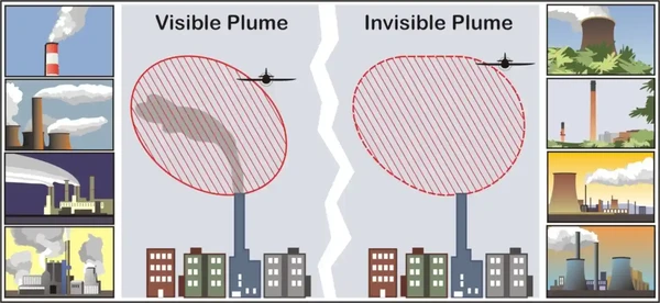
- Exhaust plumes are defined as visible or invisible emissions from power plants, industrial production facilities, or other industrial systems that release large amounts of vertically directed unstable gases (effluent).
- High temperature exhaust plumes can cause significant air disturbances such as turbulence and vertical shear.
- Other identified potential hazards include, but are not necessarily limited to:
- Reduced visibility.
- Oxygen depletion.
- Engine particulate contamination.
- Exposure to gaseous oxides, and/or.
- Icing
- Results of encountering a plume may include airframe damage, aircraft upset, and/or engine damage/failure.
- These hazards are most critical during low altitude flight in calm and cold air, especially in and around approach and departure corridors or airport traffic areas.
- Whether plumes are visible or invisible, the full extent of their turbulent effect is difficult to predict.
- Some studies do predict that the significant turbulent effects of an exhaust plume can extend to heights of over 1,000 feet above the height of the top of the stack or cooling tower.
- Any effects will be more pronounced in calm stable air where the plume is very hot and the surrounding area is still and cold.
- Fortunately, studies also predict that any amount of crosswind will help to dissipate the effects.
- However, the size of the tower or stack is not a good indicator of the predicted effect the plume may produce.
- The major effects are related to the heat or size of the plume effluent, the ambient air temperature, and the wind speed affecting the plume.
- Smaller aircraft can expect to feel an effect at a higher altitude than heavier aircraft.
- When able, a pilot should steer clear of exhaust plumes by flying on the upwind side of smokestacks or cooling towers.
- When a plume is visible via smoke or a condensation cloud, remain clear and realize a plume may have both visible and invisible characteristics.
- Exhaust stacks without visible plumes may still be in full operation, and airspace in the vicinity should be treated with caution.
- As with mountain wave turbulence or clear air turbulence, an invisible plume may be encountered unexpectedly.
- Cooling towers, power plant stacks, exhaust fans, and other similar structures are depicted in []
- Pilots are encouraged to exercise caution when flying in the vicinity of exhaust plumes.
- Pilots are also encouraged to reference the Chart Supplement U.S. where amplifying notes may caution pilots and identify the location of structure(s) emitting exhaust plumes.
- The best available information on this phenomenon must come from pilots via the PIREP reporting procedures.
- All pilots encountering hazardous plume conditions are urgently requested to report time, location, and intensity (light, moderate, severe, or extreme) of the element to the FAA facility with which they are maintaining radio contact.
- If time and conditions permit, elements should be reported according to the standards for other PIREPs (Pilot Weather Reports) and position reports.
Thermal Soaring Interactive Scenario
The Fading-Lift Glider Flight
Manage a glider cross-country through thermal detection, centering, shared-lift traffic, wind drift, overdevelopment, sink, and an off-airport landing.
Scenario Complete
Thermal Soaring Knowledge Check
Choose the knowledge check that matches your current training for Thermal Soaring.
 Private Pilot
PPL knowledge check
Core Knowledge Review
Review foundational knowledge, key concepts, and practical considerations. Topic: Thermal Soaring.
- Immediate feedback
- Answer explanations
- Account progress tracking
 Commercial Pilot
CPL knowledge check
Advanced Application
Apply knowledge to advanced operations, risk management, and aeronautical decision-making. Topic: Thermal Soaring.
- Immediate feedback
- Answer explanations
- Account progress tracking
Why Take a Quiz?
Quizzes reinforce key concepts, identify knowledge gaps, and build confidence for real-world decisions. Quiz material is representative of the information provided here and is not based on or sourced from the Federal Aviation Administration test bank.
Thermal Soaring Conclusion
- Note: Landing in tow: low tow, no spoilers except to take out slack, no brakes
- Speed to fly:
- Note: Speed to fly: add 1/2 headwind, subtract 1/4 tailwind
- Note: Speed to fly for wind: for sink/lift is based off L/D=50
- MacCready number
- Turbulence experienced while thermal soaring depends less on the thermal's intensity than on its interaction with the winds aloft.
- Remember the golden rule of gliding, to never fly over (glide distance) terrain you cannot make a safe landing on
- Still looking for something? Continue searching: