Basic Attitude Instrument Flying
Basic attitude instrument flying is the control of an aircraft's spatial position by using instruments rather than ground reference.
Introduction to Basic Attitude Instrument Flying
- Attitude instrument flying is defined as control of an aircraft's spatial position by using instruments rather than ground reference
WARNING:
All procedures are GENERALIZED.
Use the Pilot Operating Handbook (POH) procedures for specific aircraft performance and limitations.
and/or current Standard Operating Procedures (SOPs).
Basic Attitude Instrument Flying Key Highlights
- Basic attitude instrument flying teaches pilots to control aircraft attitude and performance using flight instruments as primary references.
- Instrument flying requires continuous interpretation of attitude, performance, and navigation instruments to maintain precise aircraft control.
- The attitude indicator serves as the primary reference instrument for establishing and maintaining aircraft pitch and bank attitudes.
- Supporting instruments such as the altimeter, airspeed indicator, heading indicator, and VSI verify aircraft performance changes.
- Instrument scan techniques help pilots divide attention efficiently between multiple flight instruments.
- Smooth and coordinated control inputs are essential to maintain stable aircraft attitudes during instrument flight.
- Spatial disorientation and fixation can occur if pilots fail to maintain effective instrument cross-check procedures.
- Basic instrument maneuvers include straight-and-level flight, climbs, descents, turns, and unusual attitude recoveries.
- Partial panel training prepares pilots to maintain control following instrument or system failures.
- Understanding basic attitude instrument flying improves instrument proficiency, situational awareness, and overall flight safety.
Primary and Supporting Method
- Specific principal instruments indicate pitch, bank, and power control requirements during maneuvers
- These are your primary instruments while those that back up these indications will be supporting
-
Pitch Instruments:
- Attitude indicator
- Altimeter
- Airspeed Indicator
- Vertical Speed Indicator
-
Bank Instruments:
- Attitude Indicator
- Heading Indicator
- Magnetic Compass
- Turn Coordinator
-
Power Instruments:
- Airspeed Indicator
- Engine Instruments
- Manifold Pressure
- Tachometer
- Engine Pressure Ratio (EPR)
Control/Performance Method
- Use the control instruments-the attitude indicator to set or change pitch and bank and the tachometer or manifold pressure gauge to maintain or adjust airspeed and rate of climb or descent. Check the performance instruments (airspeed, altimeter, heading indicator, rate-of-turn indicator, and so forth) only to confirm the results of your control inputs. In other words, to repeat a fundamental adage of flying: Set the pitch attitude, power, and configuration (flaps and/or landing gear), and predictable performance results
Basic Attitude Instrument Flying Skills
-
Cross-Checking:
- Human error, instrument error, and atmospheric changes make it impossible to establish an attitude and keep performance constant
- Cross-checking is the continuous scanning of flight instruments to the maintain desired attitude and performance.
-
Selected Radial Cross-Check:
- 80-90% of scan is focused on the attitude indicator
- The scan begins with attitude and branches out to various other instruments, but the scan always return to attitude before checking the next instrument branches will depend on maneuver.
-
Rectangular Cross-Check:
- Scan moves in a clockwise or counter-clockwise direction around the basic six-pack, thus creating a rectangular pattern
- Gives equal weight to each instrument
- Can lengthen the time between checking instruments critical for maneuver being performed.
-
Common Cross-Check:
- Common cross-check for a beginner is rapidly looking at different instruments without knowing why or what they are looking for
- With experience the common cross-check becomes a habit, you look at the instruments needed for the given situation, you know what to look for and how long to look
-
-
Instrument Interpretation:
- Understanding the information provided by cross-checking
- Requires thorough study and analysis
- An understanding of both construction and operating principles is necessary
- The more a pilot knows about the instruments in his or her plane the better they will be able to understand the information being given to them
- By knowing trends and limitations of instruments a pilot will know what other instruments to cross-check to get the complete picture
- Such things as knowing what pitch attitudes to use for a given rate of climb or what power settings will give an approximate airspeed will reduce pilots workload
-
Aircraft Control:
- Taking the instrument information that has been interpreted and making physical adjustments to flight controls in response
- When using instruments instead of outside references the control inputs are the same, but must be smooth and precise
- There are four components to aircraft control:
-
Pitch Control:
- Controlling the rotation of the aircraft around the lateral axis by movement of the elevators in response to instrument interpretation
-
Bank Control:
- Controlling angle made by the wing and the horizon, after interpreting appropriate instruments movement of the ailerons to roll the aircraft about its longitudinal axis
-
Power Control:
- Interpretation indicates a need for adjustment in thrust
-
Trim Control:
- Trim removes control pressure once desired attitude is attained
- Improper trim will cause a need for constant force need on the controls, this adds distraction and leads to abrupt and unintentional attitude changes
-
Straight-and-Level Flight
- Straight-and-level flight demands an understanding of the relationship between pitch, bank, power.
-
Pitch Control:
- The pitch attitude of an airplane is the angle between the longitudinal axis of the airplane and the actual horizon.
- The longitudinal axis is an imaginary line running from the nose to the tail of the aircraft.
- The actual horizon is the horizon of the Earth, a reference to 'level'
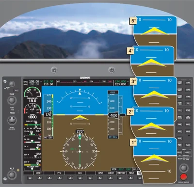
- In level flight, the pitch attitude varies with airspeed and load. For training purposes, the latter factor can normally be disregarded in small airplanes. At a constant airspeed, there is only one specific pitch attitude for level flight.
- At slow cruise speeds, the level flight attitude is nose-high with indications as in []; at fast cruise speeds, the level flight attitude is nose-low. []
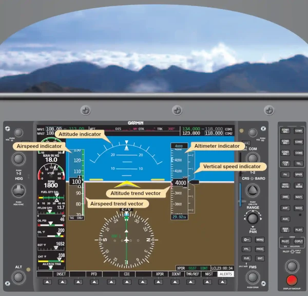
- The instruments that directly or indirectly indicate pitch on the primary flight display (PFD) are:
-
Attitude Indicator:
- The attitude indicator gives the pilot a direct indication of the pitch attitude.
- Most attitude indicators span the entire width of the PFD screen, greatly increasing the pilot's situational awareness.
- The elevator/stabilator pitches the aircraft up and down by deflecting the surface, creating a load on the tail.
- As the pilot pulls back on the control yoke causing the elevator to rise, the yellow chevron begins to show a displacement up from the artificial horizon line.
- This is caused by the AHRS unit sensing the changing angle between the longitudinal plane of the earth (actual horizon) and the longitudinal axis of the aircraft.
- The attitude indicator displayed on the PFD screen is a representation of outside visual cues.
- Rather than rely on the natural horizon visible during visual flight rules (VFR) flight, the pilot must rely on the artificial horizon of the PFD screen.
- During normal cruise airspeed, the point of the yellow chevron (aircraft symbol) is positioned on the artificial horizon.
- Unlike conventional attitude indicators, the EFD attitude indicator does not allow for manipulating the position of the chevron in relationship to the artificial horizon.
- The position is fixed and therefore always display the pitch angle as calculated by the AHRS unit.
- The attitude indicator only shows pitch attitude and does not indicate altitude.
- A pilot should not attempt to maintain level flight using the attitude indicator alone.
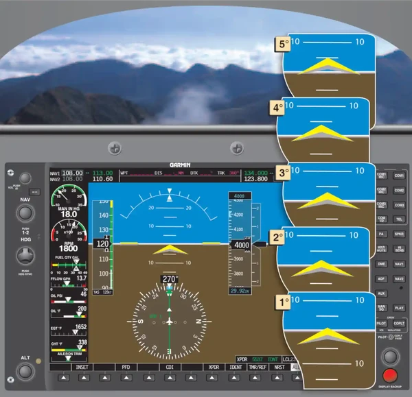
- It is important for the pilot to understand how small displacements both up and down can affect the altitude of the aircraft.
- To achieve this, the pilot should practice increasing the pitch attitude incrementally to become familiar with how each degree of pitch changes the altitude.
- In both cases, the aircraft will slow and gain altitude.
- The amount of change is relative to the airspeed flown
- The full height of the chevron is approximately 5 degrees and provides an accurate reference for pitch adjustment.
- It is imperative that the pilot make the desired changes to pitch by referencing the attitude indicator and then trimming off any excess control pressures.
- Relieving these pressures allow for a more stabilized flight and reduces pilot work load.
- Once the aircraft is trimmed for level flight, the pilot must smoothly and precisely manipulate the elevator control forces in order to change the pitch attitude.
- To master the ability to smoothly control the elevator, a pilot must develop a very light touch on the control yoke.
- The thumb and two fingers are normally sufficient to move the control yoke
- The pilot should avoid griping the yoke with a full fist.
- When a pilot grips the yoke with a full fist, there is a tendency to apply excess pressures, thus changing the aircraft attitude.
- Practice making smooth, small pitch changes both up and down until precise corrections can be made.
- With practice, a pilot is able to make pitch changes in 1 degree increments, smoothly controlling the attitude of the aircraft.
- The last step in mastering elevator control is trimming the aircraft.
- Trimming the aircraft to relieve any control pressures is essential for smooth attitude instrument flight.
-
Altimeter:
- At constant power, any deviation from level flight (except in turbulent air) must be the result of a pitch change.
- If the power is constant, the altimeter gives an indirect indication of the pitch attitude in level flight.
- Since the altitude should remain constant when the airplane is in level flight, any deviation from the desired altitude signals the need for a pitch change.
- In the PFD, as the pitch starts to change, the altitude trend indicator on the altitude tape begins to show a change in the direction of displacement.
- The rate at which the trend indicator grows and the altimeter numbers change aids the pilot in determining how much of a pitch change is necessary to stop the trend.
- At constant power, any deviation from level flight (except in turbulent air) must be the result of a pitch change.
-
Vertical Speed Indicator/VSI Tape:
- The Vertical Speed Indicator (VSI) tape provides for an indirect indication of pitch attitude and gives the pilot a more immediate indication of a pending altitude deviation.
- In addition to trend information, the vertical speed also gives a rate indication.
- By using the VSI tape in conjunction with the altitude trend tape, a pilot has a better understanding of how much of a correction needs to be made.
- With practice, the pilot will learn the performance of a particular aircraft and know how much pitch change is required to correct for a specific rate indication.
- Unlike older analog VSIs, new glass panel displays have instantaneous VSIs.
- Older units had a lag designed into the system that was utilized to indicate rate information.
- The new glass panel displays utilize a digital air data computer that does not indicate a lag.
- Altitude changes are shown immediately and can be corrected for quickly.
- The VSI tape should be used to assist in determining what pitch changes are necessary to return to the desired altitude.
- A good rule of thumb is to use a vertical speed rate of change that is double the altitude deviation.
- However, at no time should the rate of change be more than the optimum rate of climb or descent for the specific aircraft being flown.
- For example, if the altitude is off by 200 feet from the desired altitude, then a 400 feet per minute (fpm) rate of change would be sufficient to get the aircraft back to the original altitude.
- If the altitude has changed by 700 feet, then doubling that would necessitate a 1,400 fpm change.
- Most aircraft are not capable of that, so restrict changes to no more than optimum climb and descent.
- An optimum rate of change would vary between 500 and 1,000 fpm.
- One error the instrument pilot encounters is overcontrolling.
- Overcontrolling occurs when a deviation of more than 200 fpm is indicated over the optimum rate of change.
- For example, an altitude deviation of 200 feet is indicated on the altimeter, a vertical speed rate of 400 feet should be indicated on the gauge.
- If the vertical speed rate showed 600 fpm (200 more than optimum), the pilot would be overcontrolling the aircraft.
- When returning to altitude, the primary pitch instrument is the VSI tape.
- If any deviation from the desired vertical speed is indicated, make the appropriate pitch change using the attitude indicator.
- As the aircraft approaches the target altitude, the vertical speed rate can be slowed in order to capture the altitude in a more stabilized fashion.
- Normally within 10 percent of the rate of climb or descent from the target altitude, begin to slow the vertical speed rate to level off at the target altitude.
- This allows the pilot to level at the desired altitude without rapid control inputs or experiencing discomfort due to G-load.
- The Vertical Speed Indicator (VSI) tape provides for an indirect indication of pitch attitude and gives the pilot a more immediate indication of a pending altitude deviation.
-
Airspeed Indicator:
- The ASI presents an indirect indication of the pitch attitude.
- At a constant power setting and pitch attitude, airspeed remains constant.
- As the pitch attitude lowers, airspeed increases, and the nose should be raised.
- As the pitch attitude is increased, the nose of the aircraft raises, which results in an increase in the angle of attack as well as an increase in induced drag.
- The increased drag begins to slow the momentum of the aircraft, which is indicated on the ASI.
- The airspeed trend indicator shows a trend as to where the airspeed will be in 6 seconds.
- Conversely, if the nose of the aircraft should begin to fall, the angle of attack, as well as induced drag, decreases.
- There is a lag associated with the ASI when using it as a pitch instrument.
- It is not a lag associated with the construction of the ASI, but a lag associated with momentum change.
- Depending on the rate of momentum change, the ASI may not indicate a pitch change in a timely fashion.
- If the ASI is being used as the sole reference for pitch change, it may not allow for a prompt correction.
- However, if smooth pitch changes are executed, modern glass panel displays are capable of indicating 1 knot changes in airspeed and also capable of projecting airspeed trends.
- When flying by reference to flight instruments alone, it is imperative that all of the flight instruments be crosschecked for pitch control.
- By cross-checking all pitch related instruments, the pilot can better visualize the aircraft attitude at all times.
- As previously stated, the primary instrument for pitch is the instrument that gives the pilot the most pertinent information for a specific parameter.
- When in level flight and maintaining a constant altitude, what instrument shows a direct indication of altitude? The only instrument that is capable of showing altitude is the altimeter.
- The other instruments are supporting instruments that are capable of showing a trend away from altitude, but do not directly indicate an altitude.
- The supporting instruments forewarn of an impending altitude deviation. With an efficient cross-check, a proficient pilot is better able to maintain altitude.
-
- The pitch attitude of an airplane is the angle between the longitudinal axis of the airplane and the actual horizon.
-
Bank Control:
- Above assumes the aircraft is being flown in coordinated flight, which means the longitudinal axis of the aircraft is aligned with the relative wind.
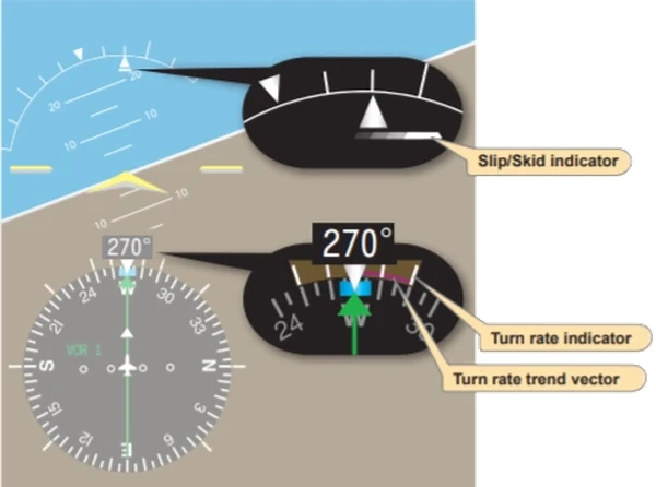
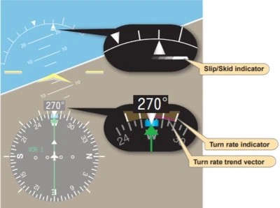
- On the PFD, the attitude indicator shows if the wings are level.
- The turn rate indicator, slip/skid indicator, and the heading indicator also indicate whether or not the aircraft is maintaining a straight (zero bank) flightpath.
-
Attitude Indicator:
- The attitude indicator is the only instrument on the PFD that has the capability of displaying the precise bank angle of the aircraft.
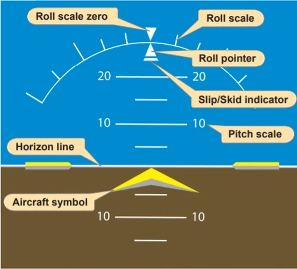
- . [] identifies the components that make up the attitude indicator display
- The top of the display is blue, representing sky, the bottom is brown, depicting dirt, and the white line separating them is the horizon.
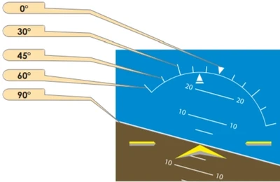
- The lines parallel to the horizon line are the pitch scale, which is marked in 5 degree increments and labeled every 10°.
- The pitch scale always remains parallel to the horizon.
- The curved line in the blue area is the roll scale.
- The triangle on the top of the scale is the zero index.
- The hash marks on the scale represent the degree of bank. [Figure 7-53].
- The roll scale always remains in the same position relative to the horizon line.
- The roll pointer indicates the direction and degree of bank.
- . [] The roll pointer is aligned with the aircraft symbol
- The roll pointer indicates the angle of the lateral axis of the aircraft compared to the natural horizon.
- The slip/skid indicator will show if the longitudinal axis of the aircraft is aligned with the relative wind, which is coordinated flight.
- With the roll index and the slip/skid indicator aligned, any deflection, either right or left of the roll index causes the aircraft to turn in that direction.
- With the small graduations on the roll scale, it is easy to determine the bank angle within approximately 1 degree.
- In coordinated flight, if the roll index is aligned with the roll pointer, the aircraft is achieving straight flight.
- An advantage of EFDs is the elimination of the precession error.
- Precession error in analog gauges is caused by forces being applied to a spinning gyro.
- With the new solid state instruments, precession error has been eliminated.
- Since the attitude indicator is capable of showing precise pitch and bank angles, the only time that the attitude indicator is a primary instrument is when attempting to fly at a specific bank angle or pitch angle.
- Other times, the attitude instrument can be thought of as a control instrument.
-
Horizontal Situation Indicator:
- The horizontal situation indicator (HSI) is a rotating 360° compass card that indicates magnetic heading.
- The HSI is the only instrument that is capable of showing exact headings.
- The magnetic compass can be used as a backup instrument in case of an HSI failure; however, due to erratic, unstable movements, it is more likely to be used a supporting instrument
- For the pilot to achieve the desired rate of change, it is important for him or her to understand the relationship between the rate at which the HSI changes heading displays and the amount of bank angle required to meet that rate of change.
- A very small rate of heading change means the bank angle is small, and it takes more time to deviate from the desired straight flightpath.
- A larger rate of heading change means a greater bank angle happens at a faster rate.
- The horizontal situation indicator (HSI) is a rotating 360° compass card that indicates magnetic heading.
-
Heading Indicator:
- The heading indicator is the large black box with a white number that indicates the magnetic heading of the aircraft.
- . [] The aircraft heading is displayed to the nearest degree
- When this number begins to change, the pilot should be aware that straight flight is no longer being achieved.
- The heading indicator is the large black box with a white number that indicates the magnetic heading of the aircraft.
-
Turn Rate Indicator:
- The turn rate indicator gives an indirect indication of bank.
- It is a magenta trend indicator capable of displaying halfstandard as well as standard rate turns to both the left and right.
- . [] The turn indicator is capable of indicating turns up to 4 degrees per second by extending the magenta line outward from the standard rate mark
- If the rate of turn has exceeded 4 degrees per second, the magenta line can not precisely indicate where the heading will be in the next 6 seconds; the magenta line freezes and an arrowhead will be displayed.
- This alerts the pilot to the fact that the normal range of operation has been exceeded.
-
Slip/Skid Indicator:
- The slip/skid indicator is the small portion of the lower segmented triangle displayed on the attitude indicator.
- This instrument depicts whether the aircraft's longitudinal axis is aligned with the relative wind. []
- The pilot must always remember to cross-check the roll index to the roll pointer when attempting to maintain straight flight.
- Any time the heading remains constant and the roll pointer and the roll index are not aligned, the aircraft is in uncoordinated flight.
- To make a correction, the pilot should apply rudder pressure to bring the aircraft back to coordinated flight.
- The slip/skid indicator is the small portion of the lower segmented triangle displayed on the attitude indicator.
-
Power Control:
- Power produces thrust which, with the appropriate angle of attack of the wing, overcomes the forces of gravity, drag, and inertia to determine airplane performance.
- Power control must be related to its effect on altitude and airspeed, since any change in power setting results in a change in the airspeed or the altitude of the airplane.
- At any given airspeed, the power setting determines whether the airplane is in level flight, in a climb, or in a descent.
- If the power is increased in straight-and-level flight and the airspeed held constant, the airplane climbs; if power is decreased while the airspeed is held constant, the airplane descends.
- On the other hand, if altitude is held constant, the power applied determines the airspeed.
- The relationship between altitude and airspeed determines the need for a change in pitch or power.
- If the airspeed is off the desired value, always check the altimeter before deciding that a power change is necessary.
- Think of altitude and airspeed as interchangeable; altitude can be traded for airspeed by lowering the nose, or convert airspeed to altitude by raising the nose.
- If altitude is higher than desired and airspeed is low, or vice versa, a change in pitch alone may return the airplane to the desired altitude and airspeed [Figure 7-55].
- If both airspeed and altitude are high or if both are low, then a change in both pitch and power is necessary in order to return to the desired airspeed and altitude [Figure 7-56].
- For changes in airspeed in straight-and-level flight, pitch, bank, and power must be coordinated in order to maintain constant altitude and heading.
- When power is changed to vary airspeed in straight-and-level flight, a single-engine, propeller-driven airplane tends to change attitude around all axes of movement.
- Therefore, to maintain constant altitude and heading, apply various control pressures in proportion to the change in power.
- When power is added to increase airspeed, the pitch instruments indicate a climb unless forward-elevator control pressure is applied as the airspeed changes.
- With an increase in power, the airplane tends to yaw and roll to the left unless counteracting aileron and rudder pressures are applied.
- Keeping ahead of these changes requires increasing cross-check speed, which varies with the type of airplane and its torque characteristics, the extent of power and speed change involved.
-
Power Settings:
- Power control and airspeed changes are much easier when approximate power settings necessary to maintain various airspeeds in straight-and-level flight are known in advance.
- However, to change airspeed by any appreciable amount, the common procedure is to underpower or overpower on initial power changes to accelerate the rate of airspeed change (For small speed changes, or in airplanes that decelerate or accelerate rapidly, overpowering or underpowering is not necessary).
- Consider the example of an airplane that requires 23 inches of mercury ("Hg) to maintain a normal cruising airspeed of 120 knots, and 18 "Hg to maintain an airspeed of 100 knots.
- The reduction in airspeed from 120 knots to 100 knots while maintaining straight-and-level flight is discussed below and illustrated in Figures 7-57, 7-58, and 7-59.
- Instrument indications, prior to the power reduction, are shown in Figure 7-57.
- The basic attitude is established and maintained on the attitude indicator.
- The specific pitch, bank, and power control requirements are detected on these primary instruments:
- Altimeter-Primary Pitch.
- Heading Indicator-Primary Bank.
- Airspeed Indicator-Primary Power.
- Supporting pitch and bank instruments are shown in Figure 7-57.
- Note that the supporting power instrument is the manifold pressure gauge (or tachometer if the propeller is fixed pitch).
- However, when a smooth power reduction to approximately 15 "Hg (underpower) is made, the manifold pressure gauge becomes the primary power instrument [Figure 7-58].
- With practice, power setting can be changed with only a brief glance at the power instrument, by sensing the movement of the throttle, the change in sound, and the changes in the feel of control pressures.
- As the thrust decreases, increase the speed of the cross-check and be ready to apply left rudder, back-elevator, and aileron control pressure the instant the pitch and bank instruments show a deviation from altitude and heading.
- As proficiency is obtained, a pilot will learn to cross-check, interpret, and control the changes with no deviation of heading and altitude.
- Assuming smooth air and ideal control technique, as airspeed decreases, a proportionate increase in airplane pitch attitude is required to maintain altitude.
- Similarly, effective torque control means counteracting yaw with rudder pressure.
- As the power is reduced, the altimeter is primary for pitch, the heading indicator is primary for bank, and the manifold pressure gauge is momentarily primary for power (at 15 "Hg in Figure 7-58).
- Control pressures should be trimmed off as the airplane decelerates.
- As the airspeed approaches the desired airspeed of 100 knots, the manifold pressure is adjusted to approximately 18 "Hg and becomes the supporting power instrument.
- The ASI again becomes primary for power [Figure 7-59].
- Power control and airspeed changes are much easier when approximate power settings necessary to maintain various airspeeds in straight-and-level flight are known in advance.
-
Airspeed Changes in Straight-and-Level Flight:
- Practice of airspeed changes in straight-and-level flight provides an excellent means of developing increased proficiency in all three basic instrument skills and brings out some common errors to be expected during training in straight-and-level flight.
- Having learned to control the airplane in a clean configuration (minimum drag conditions), increase proficiency in cross-check and control by practicing speed changes while extending or retracting the flaps and landing gear.
- While practicing, be sure to comply with the airspeed limitations specified in the POH/AFM for gear and flap operation.
- Sudden and exaggerated attitude changes may be necessary in order to maintain straight-and-level flight as the landing gear is extended and the flaps are lowered in some airplanes.
- The nose tends to pitch down with gear extension, and when flaps are lowered, lift increases momentarily (at partial flap settings) followed by a marked increase in drag as the flaps near maximum extension.
- Control technique varies according to the lift and drag characteristics of each airplane.
- Accordingly, knowledge of the power settings and trim changes associated with different combinations of airspeed, gear, and flap configurations reduces instrument cross-check and interpretation problems [Figure 7-60].
-
Airspeed Changes in Straight-and-Level Flight Procedure:
- For example, assume that in straight-and-level flight instruments indicate 120 knots with power at 23 "Hg manifold pressure/2,300 revolutions per minute (rpm), gear and flaps up.
- After reduction in airspeed, with gear and flaps fully extended, straight-and-level flight at the same altitude requires 25 "Hg manifold pressure/2,500 rpm.
- Maximum gear extension speed is 115 knots; maximum flap extension speed is 105 knots.
- Airspeed reduction to 95 knots, gear and flaps down, can be made in the following manner.
- Maintain rpm at 2,500, since a high power setting is used in full drag configuration.
- Reduce manifold pressure to 10 "Hg. As the airspeed decreases, increase cross-check speed.
- Make trim adjustments for an increased angle of attack and decrease in torque.
- Lower the gear at 115 knots. The nose may tend to pitch down and the rate of deceleration increases.
- Increase pitch attitude to maintain constant altitude and trim off some of the back-elevator pressures.
- If full flaps are lowered at 105 knots, cross-check, interpretation, and control must be very rapid.
- A simpler technique is to stabilize attitude with gear down before lowering the flaps.
- Since 18 "Hg manifold pressure holds level flight at 100 knots with the gear down, increase power smoothly to that setting as the ASI shows approximately 105 knots, and retrim.
- The attitude indicator now shows approximately two-and-a-half bar width nose-high in straight-and-level flight.
- Actuate the flap control and simultaneously increase power to the predetermined setting (25 "Hg) for the desired airspeed, and trim off the pressures necessary to hold constant altitude and heading.
- The attitude indicator now shows a bar width nose-low in straight-and-level flight at 95 knots.
- For example, assume that in straight-and-level flight instruments indicate 120 knots with power at 23 "Hg manifold pressure/2,300 revolutions per minute (rpm), gear and flaps up.
- Practice of airspeed changes in straight-and-level flight provides an excellent means of developing increased proficiency in all three basic instrument skills and brings out some common errors to be expected during training in straight-and-level flight.
-
Trim Technique:
- Trim control is one of the most important flight habits to cultivate.
- Trimming refers to relieving any control pressures that need to be applied by the pilot to the control surfaces to maintain a desired flight attitude.
- The desired result is for the pilot to be able to take his or her hands off the control surfaces and have the aircraft remain in the current attitude.
- Once the aircraft is trimmed for hands-off flight, the pilot is able to devote more time to monitoring the flight instruments and other aircraft systems.
- To trim the aircraft, apply pressure to the control surface that needs trimming and roll the trim wheel in the direction pressure is being held.
- Relax the pressure that is being applied to the control surface and monitor the primary instrument for that attitude.
- If the desired performance is achieved, fly hands off.
- If additional trimming is required, redo the trimming steps.
- An aircraft is trimmed for a specific airspeed, not pitch attitude or altitude.
- Any time an aircraft changes airspeed, there is a need to re-trim.
- For example, an aircraft is flying at 100 knots straight-and-level.
- An increase of 50 rpm causes the airspeed to increase.
- As the airspeed increases, additional lift is generated and the aircraft climbs.
- Once the additional thrust has stabilized at some higher altitude, the airspeed will again stabilize at 100 knots.
- This demonstrates how trim is associated with airspeed and not altitude.
- If the initial altitude is to be maintained, forward pressure would need to be applied to the control wheel while the trim wheel needs to be rolled forward to eliminate any control pressures.
- Rolling forward on the trim wheel is equal to increasing for a trimmed airspeed.
- Any time the airspeed is changed, re-trimming is required.
- Trimming can be accomplished during any transitional period; however, prior to final trimming, the airspeed must be held constant.
- If the airspeed is allowed to change, the trim is not adjusted properly and the altitude varies until the airspeed for which the aircraft is trimmed is achieved.
- Trim control is one of the most important flight habits to cultivate.
-
Straight-and-Level Flight Common Errors:
- Pitch errors usually result from the following errors:
- Improper adjustment of the yellow chevron (aircraft symbol) on the attitude indicator.
- Corrective Action: Once the aircraft has leveled off and the airspeed has stabilized, make small corrections to the pitch attitude to achieve the desired performance. Cross-check the supporting instruments for validation.
- Insufficient cross-check and interpretation of pitch instruments. [Figure 7-61].
- Example: The airspeed indication is low. The pilot, believing a nose-high pitch attitude exists, applies forward pressure without noting that a low power setting is the cause of the airspeed discrepancy.
- Corrective Action: Increase the rate of cross-check of all the supporting flight instruments. Airspeed and altitude should be stabilized before making a control input.
- Acceptance of deviations.
- Example: A pilot has an altitude range of ±100 feet according to the practical test standards for straight-and level-flight. When the pilot notices that the altitude has deviated by 60 feet, no correction is made because the altitude is holding steady and is within the standards.
- Corrective Action: The pilot should cross-check the instruments and, when a deviation is noted, prompt corrective actions should be taken in order to bring the aircraft back to the desired altitude. Deviations from altitude should be expected but not accepted.
- Overcontrolling-excessive pitch changes.
- Example: A pilot notices a deviation in altitude. In an attempt to quickly return to altitude, the pilot makes a large pitch change. The large pitch change destabilizes the attitude and compounds the error.
- Corrective Action: Small, smooth corrections should be made in order to recover to the desired altitude (0.5° to 2° depending on the severity of the deviation). Instrument flying is comprised of small corrections to maintain the aircraft attitude. When flying in IMC, a pilot should avoid making large attitude changes in order to avoid loss of aircraft control and spatial disorientation.
- Failure to maintain pitch corrections.
- Pitch changes need to be made promptly and held for validation. Many times pilots make corrections and allow the pitch attitude to change due to not trimming the aircraft. It is imperative that any time a pitch change is made; the trim is readjusted in order to eliminate any control pressures that are being held A rapid cross-check aids in avoiding any deviations from the desired pitch attitude.
- Example: A pilot notices a deviation in altitude. A change in the pitch attitude is accomplished but no adjustment to the trim is made. Distractions cause the pilot to slow the cross-check and an inadvertent reduction in the pressure to the control column commences. The pitch attitude then changes, thus complicating recovery to the desired altitude.
- Corrective Action: The pilot should initiate a pitch change and then immediately trim the aircraft to relieve any control pressures. A rapid cross-check should be established in order to validate the desired performance is being achieved.
- Fixation during cross-check.
- Devoting an unequal amount of time to one instrument either for interpretation or assigning too much importance to an instrument. Equal amounts of time should be spent during the cross-check to avoid an unnoticed deviation in one of the aircraft attitudes.
- Example: A pilot makes a correction to the pitch attitude and then devotes all of the attention to the altimeter to determine if the pitch correction is valid. During this time, no attention is paid to the heading indicator, which shows a turn to the left. [Figure 7-62].
- Corrective Action: The pilot should monitor all instrumentation during the cross-check. Do not fixate on one instrument waiting for validation. Continue to scan all instruments to avoid allowing the aircraft to begin a deviation in another attitude.
- Improper adjustment of the yellow chevron (aircraft symbol) on the attitude indicator.
- Heading errors usually result from but are not limited to the following errors:
- Failure to cross-check the heading indicator, especially during changes in power or pitch attitude.
- Misinterpretation of changes in heading, with resulting corrections in the wrong direction.
- Failure to note and remember a preselected heading.
- Failure to observe the rate of heading change and its relation to bank attitude.
- Overcontrolling in response to heading changes, especially during changes in power settings.
- Anticipating heading changes with premature application of rudder pressure.
- Failure to correct small heading deviations. Unless zero error in heading is the goal, a pilot will tolerate larger and larger deviations. Correction of a 1 degree error takes far less time and concentration than correction of a 20° error.
- Correcting with improper bank attitude. If correcting a 10° heading error with a 20° bank correction, the aircraft will roll past the desired heading before the bank is established, requiring another correction in the opposite direction. Do not multiply existing errors with errors in corrective technique.
- Failure to note the cause of a previous heading error and thus repeating the same error. For example, the airplane is out of trim with a left wing low tendency. Repeated corrections for a slight left turn are made, yet trim is ignored.
- Power errors usually result from but are not limited to the following errors:
- Failure to become familiar with the aircraft's specific power settings and pitch attitudes.
- Abrupt use of throttle.
- Failure to lead the airspeed when making power changes, climbs, or descents.
- Example: When leveling off from a descent, increase the power in order to avoid the airspeed from bleeding off due to the decrease in momentum of the aircraft. If the pilot waits to bring in the power until after the aircraft is established in the level pitch attitude, the aircraft will have already decreased below the speed desired, which will require additional adjustment in the power setting.
- Fixation on airspeed tape or manifold pressure indications during airspeed changes, resulting in erratic control of airspeed, power, as well as pitch and bank attitudes.
- Trim errors usually result from the following faults:
- Improper adjustment of seat or rudder pedals for comfortable position of legs and feet. Tension in the ankles makes it difficult to relax rudder pressures.
- Confusion about the operation of trim devices, which differ among various airplane types. Some trim wheels are aligned appropriately with the airplane's axes; others are not. Some rotate in a direction contrary to expectations.
- Failure to understand the principles of trim and that the aircraft is being trimmed for airspeed, not a pitch attitude.
- Faulty sequence in trim techniques. Trim should be utilized to relieve control pressures, not to change pitch attitudes. The proper trim technique has the pilot holding the control wheel first and then trimming to relieve any control pressures. Continuous trim changes are required as the power setting is changed. Utilize the trim continuously, but in small amounts.
- Pitch errors usually result from the following errors:
-
Partial Panel Flight:
- One important skill to practice is partial panel flight by referencing the altimeter as the primary pitch indicator.
- Practice controlling the pitch by referencing the altitude tape and trend indicator alone without the use of the attitude indicator.
- Pilots need to learn to make corrections to altitude deviations by referencing the rate of change of the altitude tape and trend indicator.
- When operating in IMC and in a partial panel configuration, the pilot should avoid abrupt changes to the control yoke.
- Reacting abruptly to altitude changes can lead to large pitch changes and thus a larger divergence from the initial altitude.
- When a pilot is controlling pitch by the altitude tape and altitude trend indicators alone, it is possible to overcontrol the aircraft by making a larger than necessary pitch correction.
- Overcontrolling causes the pilot to move from a nose-high attitude to a nose-low attitude and vice versa.
- Small changes to pitch are required to insure prompt corrective actions are taken to return the aircraft to its original altitude with less confusion.
- When an altitude deviation occurs, two actions need to be accomplished.
- First, make a smooth control input to stop the needle movement.
- Once the altitude tape has stopped moving, make a change to the pitch attitude to start back to the entry altitude.
- During instrument flight with limited instrumentation, it is imperative that only small and precise control inputs are made.
- Once a needle movement is indicated denoting a deviation in altitude, the pilot needs to make small control inputs to stop the deviation.
- Rapid control movements only compound the deviation by causing an oscillation effect.
- This type of oscillation can quickly cause the pilot to become disoriented and begin to fixate on the altitude.
- Fixation on the altimeter can lead to a loss of directional control as well as airspeed control.
- As a general rule of thumb, for altitude deviations less than 100 feet, utilize a pitch change of 1 degree, which equates to 1⁄5 of the thickness of the chevron.
- Small incremental pitch changes allow the performance to be evaluated and eliminate overcontrolling of the aircraft.
- Instrumentation needs to be utilized collectively, but failures will occur that leave the pilot with only limited instrumentation.
- That is why partial panel flying training is important. If the pilot understands how to utilize each instrument independently, no significant change is encountered in carrying out the flight when other instruments fail.
- One important skill to practice is partial panel flight by referencing the altimeter as the primary pitch indicator.
-
Fixation:
- The tendency to stare at one instrument and negate the rest
- If off altitude, you may stare at altimeter until the desired altitude is regained
- While a change in the bank is occurring tendency will be to stare at heading indicator until reaching the desired heading, this will negate all power and pitch instruments
- The tendency to stare at one instrument and negate the rest
-
Omission:
- Leaving a particular instrument out of scan
- In a climb, you may reference attitude, airspeed, and vertical speed but inadvertently omit altimeter
- Leaving a particular instrument out of scan
-
Emphasis:
- Checking one or a few instruments more readily than the rest
- Generally the case with less experienced pilots because they may not understand an instrument fully, and tendency is to rely on what you know
- Students may be able to hold altitude well by use of altimeter but can not do so with only using the attitude indicator
- With low time pilots, there is a tendency to either not believe instruments because they do not agree with what they "feel" is right or the pilot will omit instrument errors
- With more experienced pilots, a standard interpretation error is the tendency to carry over knowledge from one plane to the next
- Example: flying a low-performance plane like a high-performance one
- As a pilot becomes familiar with a specific aircraft's instruments, he or she learns to correlate pitch changes, altimeter tapes, and altitude trend indicators.
- By adding the altitude tape display and the altitude trend indicator into the scan along with the attitude indicator, a pilot starts to develop the instrument cross-check.
- Consider flying partial panel maneuvers in VMC conditions only, to increase the margin of safety
- Consider recovering all basic attitude instrument maneuvers no lower than 1,500' AGL
- Remember, an instrument scan is everything! Not just your basic six pack
- Remain mindful that performance calculations are usually more optimistic than actual performance.
- Consider practicing maneuvers on a flight simulator to introduce yourself to maneuvers or knock-off rust
- Still looking for something? Continue searching:
- Federal Aviation Administration - Pilot/Controller Glossary.
- Instrument Flying Handbook


Basic Attitude Instrument Flying Interactive Scenario
Interactive Scenario
Loading scenario details...
Decision 1
0%
Scenario Complete
Constant Airspeed Climbs
Basic Attitude Instrument Flying Common Errors
Basic Attitude Instrument Flying Knowledge Check
Private Pilot

Core Knowledge Review
Review the foundational knowledge, key concepts, and practical considerations for Basic Attitude Instrument Flying.
Foundational
Immediate Feedback
Answer Explanations
Commercial Pilot

Advanced Application
Apply your knowledge of Basic Attitude Instrument Flying to advanced operational scenarios, risk management, and aeronautical decision-making.
Advanced
Scenario Based
Risk Management
Why Take a Quiz?
Quizzes reinforce key concepts, identify knowledge gaps, and build confidence for real-world decisions in the cockpit. Quiz material is representative of the information provided here and is not based on or sourced from the Federal Aviation Administration test bank.