Multiengine Operations
Multi-engine operations are more than having to start a second engine; however, their procedures are not so different as to be considered daunting.
Introduction to Multiengine Operations
- Multi-engine aircraft are defined by the FAA as a distinct class, primarily due to their one-engine inoperative flight characteristics.
- Although multi-engine aircraft sometimes have more advanced systems, these systems are encapsulated with a complex rating.
- There are two main considerations for OEI operations: performance and control. Multiengine pilots learn to operate the airplane for maximum rate of climb performance at the blue radial indicated airspeed by training to fly without sideslip. Pilots also learn to recognize and recover from loss of directional control associated with the red radial indicated airspeed by performing a VMC demonstration. Since the object of a VMC demonstration is not performance, sideslip occurs during the maneuver. Detailed discussion on both the loss of directional control and maximum OEI climb performance follows.
Multiengine Operations Key Highlights
- Multiengine operations involve managing aircraft equipped with more than one engine while accounting for asymmetric thrust and performance considerations.
- Engine failures in multiengine aircraft create yaw, roll, and performance challenges that require prompt corrective action.
- Vmc represents the minimum controllable airspeed with one engine inoperative under specified conditions.
- Proper identification, verification, and securing of failed engines are critical during multiengine emergency procedures.
- Pilots must manage directional control using coordinated rudder, aileron, and power inputs during asymmetric thrust conditions.
- Single-engine performance depends on aircraft weight, density altitude, configuration, and pilot technique.
- Multiengine aircraft often provide improved climb performance, redundancy, and operational capability compared to single-engine aircraft.
- Improper engine-out procedures can lead to loss of control or inability to maintain altitude during critical flight phases.
- Pilots should understand critical engine concepts, feathering systems, and performance limitations during multiengine operations.
- Understanding multiengine operations improves aircraft systems knowledge, emergency preparedness, and overall flight safety.
Single-Engine Performance in Multi-Engine Aircraft
- The most distinct difference between single and multi-engine aircraft operations involve single-engine performance.
- In a multi-engine airplane, loss of thrust from one engine affects both performance and control (versus control only in a single engine aircraft).
- With a loss of 50 percent of the engine power comes a reduced climb performance of 80 to 90%.
- Asymmetrical thrust creates control issues with thrust generation on the wing producing a yawing and rolling moment about the vertical and logitudinal axis.
- There is a dramatic performance loss associated with the loss of an engine, particularly just after takeoff.
- Any airplane's climb performance is a function of thrust horsepower, which is in excess of that required for level flight.
- In a hypothetical twin with each engine producing 200 thrust horsepower, assume that the total level flight thrust horsepower required is 175.
- In this situation, the airplane would ordinarily have a reserve of 225 thrust horsepower available for climb.
- Loss of one engine would leave only 25 (200 minus 175) thrust horsepower available for climb, a drastic reduction.
Identifying an Inoperative Engine
- Engines can fail in various modes, from partial (degraded performance) to complete (catastrophic).
- When an engine failures or engine performance degrades to such a level that directional control requires abnormal control inputs, pilots must identify the underperforming engine.
- One way is to consider the addage, "dead foot, dead engine."
- What this means is, if the left engine fails, the aircraft will inherently yaw in that direction and therefore right rudder is required to counteract.
- The left foot would then be idle, not required to provide a control input.
- The foot not performing a task is the "dead food" meaning the "dead engine" is the left engine.
- Since engine performance may still be present (degraded engine), the "dead foot, dead engine" addage remains true, but less dramatic.
- Of course, engine instruments should be referenced to confirm degraded RPM, manifold pressures, etc.
- This data provides verification of the already suspected information.
- With the engine identified and verified, the engine must then be feathered (if able) using the appropriate procedure outlined in the Pilot Operating Handbook.
Derivation of VMC
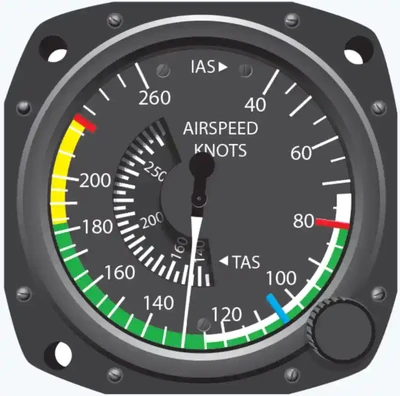
- VMC is a speed established by the manufacturer, published in the AFM/POH, and marked on most airspeed indicators with a red radial line.
- However, VMC is not a fixed airspeed under all conditions.
- VMC is a fixed airspeed only for the very specific set of circumstances under which it was determined during aircraft certification.
- The VMC noted in practice and demonstration, or in actual OEI operation, could be less or even greater than the published value, depending on conditions and pilot technique.
- During aircraft certification, the aircraft is tested under dynamic and static conditions:
- Dynamic Conditions:
- Historically, VMC is the sea level calibrated airspeed at which, when the critical engine is suddenly made inoperative (dynamic conditions), it is possible to maintain control of the airplane with that engine still inoperative and then maintain straight flight at the same speed with an angle of bank not more than 5°.
- Static (Steady-State) Conditions:
- The static determination is simply the ability to maintain straight flight at VMC with a bank angle of not more than 5°.
- This more closely resembles the VMC demonstration task in the practical test for a multiengine rating.
- Dynamic Conditions:
- If there is a difference between the dynamic and static speeds, the higher of the two is published as VMC.
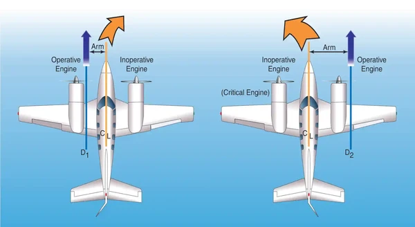
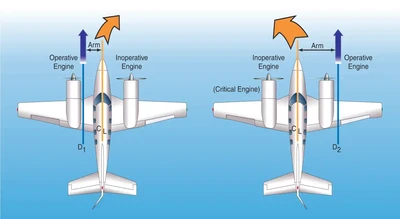
- The AFM/POH-published VMC is determined with the critical engine inoperative.
- The critical engine is the engine whose failure had the most adverse effect on directional control.
- On twins with each engine rotating in conventional, clockwise rotation as viewed from the pilot's seat, the critical engine will be the left engine.
- Multiengine airplanes are subject to P-factor just as single-engine airplanes are.
- The descending propeller blade of each engine will produce greater thrust than the. ascending blade when the airplane is operated under power and at positive angles of attack.
- The descending propeller blade of the right engine is also a greater distance from the center of gravity, and therefore has a longer moment arm than the descending propeller blade of the left engine.
- As a result, failure of the left engine will result in the most asymmetrical thrust (adverse yaw) as the right engine will be providing the remaining thrust. []
- Many twins are designed with a counter-rotating right engine. With this design, the degree of asymmetrical thrust is the same with either engine inoperative. No engine is more critical than the other, and a VMC demonstration may be performed with either engine windmilling.
Factors Impacting Minimum Controllable Airspeed (VMC)
- 14 CFR part 23, section 149, provides certification guidance.
- The outlined conditions also describe how manufacturers perform dynamic testing, which results in the published VMC speed.
-
Minimum Controllable Airspeed versus Power:
- VMC increases as power increases on the operating engine.
- With normally aspirated engines, VMC is highest at takeoff power and sea level, and decreases with altitude.
- With turbocharged engines, takeoff power, and therefore VMC, remains constant with increases in altitude up to the engine's critical altitude (the altitude where the engine can no longer maintain 100 percent power).
- Above the critical altitude, VMC decreases just as it would with a normally aspirated engine whose critical altitude is sea level.
- VMC increases as power increases on the operating engine.
-
Minimum Controllable Airspeed versus Propeller:
- VMC increases with increased drag on the inoperative engine.
- VMC is highest, therefore, when the critical engine propeller is windmilling at the low pitch, high rpm blade angle.
- VMC is normally determined with the critical engine propeller windmilling in the takeoff position, unless the engine is equipped with an autofeather system.
-
Minimum Controllable Airspeed versus Weight & Center of Gravity:
- VMC increases as the center of gravity (CG) moves aft.
- The moment arm of the rudder reduces, reducing its effectiveness, as the CG moves aft.
- For a typical light twin, the aft-most CG limit is the most unfavorable CG position.
- Historically, 14 CFR Part 23 requires manufacturers to determine VMC at the most unfavorable weight.
- For twins certified under CAR 3 or early 14 CFR Part 23, the weight manufacturers would determine that VMC was not specified. VMC increases as the weight reduces. [Figure 13-13].
-
Minimum Controllable Airspeed versus Configuration:
- VMC increases when the landing gear is retracted.
- Extended landing gear aids directional stability, which tends to decrease VMC.
- VMC decreases when the flaps are down.
- The extra drag on the side with the operative engine helps stabilize the aircraft (counteracting yaw).
-
Minimum Controllable Airspeed versus Bank Angle:
- Bank angles into the good engine decrease VMC while bank angles into the dead engine increase VMC.
- Bank angles into the dead engine lower VMC, as using high bank angles reduces the required rudder deflection.
- VMC may decrease by more than 3 knots for each degree of bank increase between wing-level and 5°.
- Therefore, if flying wings-level, VMC may be 15-20 knots higher than published (which is determined using up to a 5° bank angle).
- However, this method may result in unsafe flight due to both the large sideslip and the need to increase the angle of attack to maintain the vertical component of lift.
Minimum Controllable (VMC) Demonstration
- The actual demonstration of VMC and recovery in flight training more closely resembles static VMC determination in aircraft certification.
- For a safe demonstration, the pilot selects an altitude that will allow performance of the maneuver at least 3,000 feet AGL.
- The following description assumes a twin with non-counter-rotating engines, where the left engine is critical.
-
Minimum Controllable Airspeed Demonstration Procedure:
- With the landing gear retracted and the flaps set to the takeoff position, the pilot slows the airplane to approximately 10 knots above VSSE or VYSE (whichever is higher) and trims for takeoff.
- For the remainder of the maneuver, the trim setting remains unaltered.
- The pilot selects an entry heading and sets high rpm on both propeller controls.
- Power on the left engine is throttled back to idle as the right engine power is advanced to the takeoff setting.
- The landing gear warning horn will sound as long as a throttle is retarded, however the pilot listens carefully for the stall warning horn or watches for the stall warning light.
- The left yawing and rolling moment of the asymmetrical thrust is counteracted primarily with right rudder.
- A bank angle of up to 5° (a right bank in this case) may be established as appropriate for the airplane make and model.
- While maintaining entry heading, the pitch attitude is slowly increased to decelerate at a rate of 1 knot per second (no faster).
- As the airplane slows and control effectivity decays, the pilot counteracts the increasing yawing tendency with additional rudder pressure.
- Aileron displacement will also increase in order to maintain the established bank.
- An airspeed is soon reached where full right rudder travel and up to a 5° right bank can no longer counteract the asymmetrical thrust, and the airplane will begin to yaw uncontrollably to the left.
- The moment the pilot first recognizes the uncontrollable yaw, or experiences any symptom associated with a stall, the pilot simultaneously retards the throttle for the operating engine to stop the yaw and lowers the pitch attitude to regain speed.
- Recovery is made to straight flight on the entry heading at VSSE or VYSE.
- The pilot increases power to the operating engine, and demonstrates controlled flight before restoring symmetrical power.
- With the landing gear retracted and the flaps set to the takeoff position, the pilot slows the airplane to approximately 10 knots above VSSE or VYSE (whichever is higher) and trims for takeoff.
- Key factors:
- The rudder pressure during the demonstration can be quite high.
- During certification under historical 14 CFR part 23, section 23.149(e), 150 pounds of force was permitted.
- Most twins will run out of rudder travel long before 150 pounds of pressure is required.
- Maintaining altitude is not a criterion in accomplishing this maneuver.
- This is a demonstration of controllability, not performance.
- Many airplanes will lose (or gain) altitude during the demonstration.
- Remaining at or above a minimum of 3,000 feet AGL throughout the maneuver is considered to be effective risk mitigation of certain hazards.
- The rudder pressure during the demonstration can be quite high.
- Transitioning pilots should understand that attempting to demonstrate VMC with an engine cut from high power, or intentionally failing an engine at speeds less than VSSE creates a high likelihood for loss of control and an accident.
- Stall Considerations:
- While VMC decreases with altitude (non-aspirated engines), stalling speed (VS), remains the same.
- Published VMC is almost always higher than VS at sea level with a decreasing margin until at some altitude, VMC and VS are the same. [Figure 13-14].
- Should a stall occur while the airplane is under asymmetrical power, a spin entry is likely.
- The yawing moment induced from asymmetrical thrust is little different from that induced by full rudder in an intentional spin in the appropriate model of single-engine airplane.
- In this case, however, the airplane will depart controlled flight in the direction of the idle engine, not in the direction of applied rudder.
- Twins are not required to demonstrate recoveries from spins, and their spin recovery characteristics are generally very poor.
- Where VS is encountered before VMC, the departure from controlled flight might be quite sudden, with strong yawing and rolling tendencies to the inverted orientation and a spin entry.
- Therefore, during a VMC demonstration, if there are any symptoms of an impending stall such as a stall warning light or horn, airframe or elevator buffet, or sudden loss of control effectiveness; the pilot should terminate the maneuver immediately by reducing the angle of attack as the throttle is retarded and return the airplane to the entry airspeed.
- Note that noise within the flight deck may mask the sound of the stall warning horn.
- A VMC demonstration that is allowed to degrade into a single-engine stall with high asymmetrical thrust may result in an unrecoverable loss of control and a fatal accident.
- An actual demonstration of VMC may not be possible under certain conditions of density altitude, or with airplanes whose VMC is equal to or less than VS.
- Under those circumstances, as a training technique, a demonstration of VMC may safely be conducted by artificially limiting rudder travel to simulate maximum available rudder.
- A speed well above VS (approximately 20 knots) is recommended when limiting rudder travel.
- The rudder limiting technique avoids the hazards of spinning as a result of stalling with high asymmetrical power, yet is effective in demonstrating the loss of directional control.
- To reduce the risk of a loss of control, avoid performing any VMC demonstration from a high pitch attitude with both engines operating and then reducing power on one engine.
Multiengine Operations Procedure
- Set fuel selector to BOTH or the fullest tank
- Set the mixture control, as required
- Note your initial heading and the heading you wish to roll out on to perform the next maneuver
- Pick a reference point 90-180° to your left or right
- You may have to base your initial direction off any airspace restrictions you may have
- If there are no airspace restrictions, consider turning to the left first as overtaking aircraft will pass on the right.
- Perform a level turn at about 30° for 90-180° to put the nose of the aircraft on this point
- Set power, as required.
- If flying a high-wing aircraft, raise your wing first, to clear that direction before turning
- If flying a low-wing aircraft, apply common sense to bank angle if clearing below you is especially important for an upcoming maneuver (e.g., stalls)
- Look for other aircraft or hazards through the entire turn in ALL directions
- This includes up and down, especially if you intend to do any maneuver which will require an excessive change in altitude
- Once the wings are leveled on your reference point, take another look around and then begin a turn for 90-180° back to the original heading or to the heading of the next maneuver
- Throughout the entire turn, look in ALL directions
- Assuming no conflicting traffic is observed, complete appropriate checklist/commence the maneuver to be performed
- If conflicting traffic is observed, deconflict over the radio as able or find a new working area
Multiengine Operations Common Errors
- Gaining or loosing altitude
- Poor coordination
- Abrupt control usage
- Inadequate visual lookout for other aircraft
- Clearing only a small portion of sky due to short turns
Multiengine Weight & Balance Considerations
-
Multiengine Airplane Weight Considerations:
- Some multiengine airplanes have a ramp weight, which is in excess of the maximum takeoff weight.
- The ramp weight allows for fuel that would be burned during taxi and run-up, permitting a takeoff at full maximum takeoff weight.
- The airplane should weigh no more than maximum takeoff weight at the beginning of the takeoff roll.
- A maximum landing weight is a limitation against landing at a weight in excess of the published value.
- This requires preflight planning of fuel burn to ensure that the airplane weight upon arrival at destination is at or below the maximum landing weight.
- In the event of an emergency requiring an immediate landing, the pilot should recognize that the structural margins designed into the airplane are not fully available when over landing weight.
- An overweight landing inspection may be advisable—the service manual or manufacturer should be consulted.
- Some multiengine airplanes have a ramp weight, which is in excess of the maximum takeoff weight.
-
Multiengine Airplane Center of Gravity Considerations:
- The flight characteristics of the multiengine airplane vary significantly with shifts of the center of gravity (CG) within the approved envelope.
- Forward CG limits are usually determined in certification by elevator/stabilator authority in the landing round out.
- Aft CG limits are determined by the minimum acceptable longitudinal stability.
- Some multiengine airplanes may require ballast to remain within CG limits under certain loading conditions.
- Several models require ballast in the aft baggage compartment with only a learner and instructor on board to avoid exceeding the forward CG limit.
- When passengers are seated in the aft-most seats of some models, ballast or baggage may be required in the nose baggage compartment to avoid exceeding the aft CG limit.
- Most multiengine airplanes have general loading recommendations in the weight and balance section of the AFM/POH.
- When ballast is added, it should be securely tied down, and it should not exceed the maximum allowable floor loading.
- Some airplanes make use of a special weight and balance plotter.
- It consists of several movable parts that can be adjusted over a plotting board on which the CG envelope is printed.
- The reverse side of the typical plotter contains general loading recommendations for the particular airplane.
- A pencil line plot can be made directly on the CG envelope imprinted on the working side of the plotting board. This plot can easily be erased and recalculated anew for each flight.
- This plotter is to be used only for the make and model airplane for which it was designed.
- The flight characteristics of the multiengine airplane vary significantly with shifts of the center of gravity (CG) within the approved envelope.
Multiengine Stall/Spin Awareness Considerations
-
Multiengine Stall Training Considerations:
- Stall characteristics vary among multiengine airplanes just as they do with single-engine airplanes, and therefore, a pilot should be familiar with them.
- Yet, the most important stall recovery step in a multiengine airplane is the same as it is in all airplanes: reduce the angle of attack (AOA).
- Following a reduction in the AOA and the stall warning being eliminated, the wings should be rolled level and power added as needed.
- Immediate full application of power in a stalled condition has an associated risk due to the possibility of asymmetric thrust.
- In addition, single-engine stalls, or stalls with significantly more power on one engine than the other, should not be attempted due to the likelihood of a departure from controlled flight and possible spin entry.
- Similarly, simulated engine failures should not be performed during stall entry and recovery.
- Stall characteristics vary among multiengine airplanes just as they do with single-engine airplanes, and therefore, a pilot should be familiar with them.
-
Multiengine Full Stall Considerations:
- It is not recommended that full stalls be practiced unless a qualified flight instructor is present.
- A power-off or power-on full stall should only be practiced in a structured lesson with clear learning objectives and cautions discussed.
- The goals of the training are (a) to provide the pilots the experience of the handling characteristics and dynamic cues (e.g., buffet, roll off) near and at full stall and (b) to reinforce the proper application of the stall recovery procedures.
- Given the associated risk of asymmetric thrust at high angles of attack and low rudder effectiveness due to low airspeeds, this reinforces the primary step of first lowering the AOA, which allows all control surfaces to become more effective and allows for roll to be better controlled.
- Thrust should only be used as needed in the recovery.
-
Multiengine Spin Awareness Considerations:
- No multiengine airplane is approved for spins, and their spin recovery characteristics are generally very poor.
- It is therefore prudent to practice spin avoidance and maintain a high awareness of situations that can result in an inadvertent spin.
- To spin any airplane, a stalled condition needs to exist.
- At the stall, the presence or introduction of a yawing moment can initiate spin entry.
- In a multiengine airplane, the yawing moment may be generated by rudder input or asymmetrical thrust.
- It follows, then, that spin awareness be at its greatest during VMC demonstrations, stall practice, slow flight, or any condition of high asymmetrical thrust, particularly at low speed/high AOA.
- Single-engine stalls are not part of any multiengine training curriculum.
- No engine failure should ever be introduced below safe, intentional one-engine inoperative speed (VSSE).
- If no VSSE is published, use VYSE.
- Other than training situations, the multiengine airplane is only operated below VSSE for mere seconds just after lift-off or during the last few dozen feet of altitude in preparation for landing.
- For spin avoidance when practicing engine failures, the flight instructor should pay strict attention to the maintenance of proper airspeed and bank angle as the learner executes the appropriate procedure.
- The instructor should also be particularly alert during stall and slow flight practice.
- While flying with a center-of-gravity closer to the forward limit provides better stall and spin avoidance characteristics, it does not eliminate the hazard.
- When performing a VMC demonstration, the instructor should also be alert for any sign of an impending stall.
- The learner may be highly focused on the directional control aspect of the maneuver to the extent that impending stall indications go unnoticed.
- If a VMC demonstration cannot be accomplished under existing conditions of density altitude, the instructor may, for training purposes, utilize a rudder blocking technique.
- As very few twins have ever been spin-tested (none are required to), the recommended spin recovery techniques are based only on the best information available.
- The departure from controlled flight may be quite abrupt and possibly disorienting.
- The direction of an upright spin can be confirmed from the turn needle or the symbolic airplane of the turn coordinator, if necessary.
- Do not rely on the ball position or other instruments.
- If a spin is entered, most manufacturers recommend immediately retarding both throttles to idle, applying full rudder opposite the direction of rotation, and applying full forward elevator/stabilator pressure (with ailerons neutral).
- These actions should be taken as near simultaneously as possible.
- The controls should then be held in that position until the spin has stopped.
- At that point adjust rudder pressure, back elevator pressure, and power as necessary to return to the desired flight path.
- Pilots should be aware that a spin recovery will take considerable altitude; therefore, it is critical that corrective action be taken immediately.
- No multiengine airplane is approved for spins, and their spin recovery characteristics are generally very poor.
Multiengine Takeoff & Climb Considerations
-
Multiengine Takeoff and Climb Performance and Limitations:
- Terms (some specific to multiengine aircraft) performance include:
- Accelerate-Stop Distance.
- Accelerate-Go Distance.
- Climb Gradient.
-
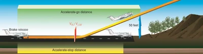
Accelerate-Stop Distance:
- Accelerate-stop distance is the runway length required to accelerate to a specified speed (either VR or VLOF, as specified by the manufacturer), experience an engine failure, and bring the airplane to a complete stop. []
-
Accelerate-Go Distance:
- Accelerate-go distance is the horizontal distance required to continue the takeoff and climb to 50 feet, assuming an engine failure at VR or VLOF, as specified by the manufacturer. []
- Terms (some specific to multiengine aircraft) performance include:
-
Multiengine Short-Field Takeoff & Climb Considerations:
- Often, partial flaps are recommended for multiengine aircraft short-field takeoff and climb procedures.
- When partial flaps are recommended for short-field takeoffs, many light-twins have a strong tendency to become airborne before VMC plus 5 knots.
- Attempting to prevent premature lift-off with forward elevator pressure results in wheel barrowing.
- To prevent this, allow the airplane to become airborne, but only a few inches above the runway.
- The pilot should be prepared to promptly abort the takeoff and land in the event of engine failure on takeoff with landing gear and flaps extended at airspeeds below VX.
- Engine failure on takeoff, particularly with obstructions, is compounded by the low airspeeds and steep climb attitudes utilized in short-field takeoffs.
- VX and VXSE are often perilously close to VMC, leaving scant margin for error in the event of engine failure as VXSE is assumed.
- If flaps were used for takeoff, the engine failure situation becomes even more critical due to the additional drag incurred.
- If VX is less than 5 knots higher than VMC, give strong consideration to reducing useful load or using another runway to increase the takeoff margins so that a short-field technique is not required.
-
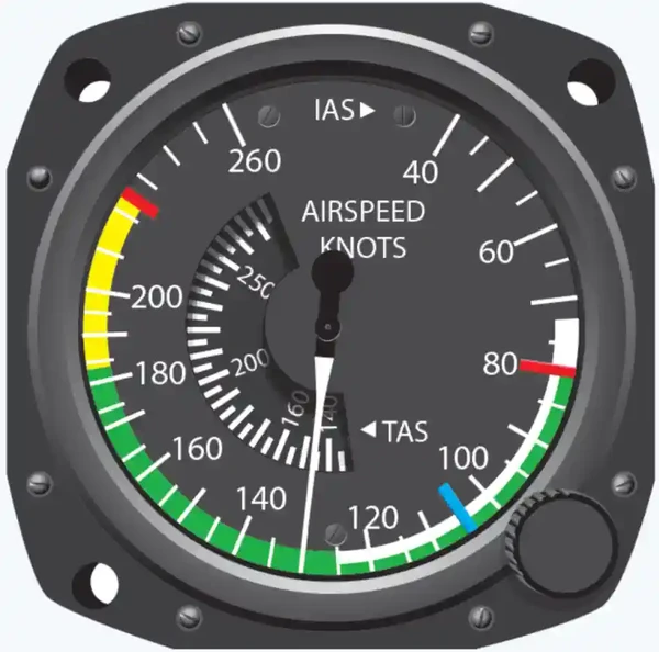
Multiengine Climb Considerations:
- Airspeed indicators on multiengine aircraft have a blue radial line which indicates VYSE.
- This blue line represents to best speed to achieve the best rate of climb and maintain directional control, if the critical engine were suddenly to become inoperative.
- Flight slower than the blue line indicates climb and/or directional control are not possible.
- In addition to using blue line speeds for climb, it is applicable to approach and landing as well.
-
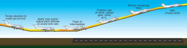
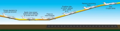
Multiengine Rejected Landings and Go-Around Considerations:
- Many multiengine airplanes have a landing gear retraction speed significantly less than the extension speed.
- Care should be exercised during the go-around not to exceed the retraction speed.
- Many multiengine airplanes have a landing gear retraction speed significantly less than the extension speed.

Multiengine Cruise Performance Considerations
- As altitude increases, VMC decreases on nonturbocharged aircraft due to the decrease in engine performance coming from each engine.
Multiengine Approach & Landing Considerations
- In addition to using blue line speeds for approaches to landing, it is applicable to takeoff and climb as well.
Multiengine Operations-Related Emergency Procedures
-
Low Altitude Engine Failure Scenarios:
- In OEI flight at low altitudes and airspeeds such as the initial climb after takeoff, pilots should operate the airplane so as to guard against the three major accident factors:
- Loss of directional control;
- Loss of performance (as much as 80% loss with OEI), and;
- Loss of flying speed.
- A takeoff or go-around is the most critical time to suffer an engine failure.
- The airplane will be slow, close to the ground, and may even have landing gear and flaps extended.
- Altitude and time is minimal.
- Until feathered, the propeller of the failed engine is windmilling, producing a great deal of drag and yawing tendency.
- Airplane climb performance is marginal or even non-existent, and obstructions may lie ahead.
- An emergency contingency plan and safety brief should be clearly understood well before the takeoff roll commences.
- An engine failure before a predetermined airspeed or point results in an aborted takeoff.
- An engine failure after a certain airspeed and point, with the gear up, and climb performance assured result in a continued takeoff.
- With loss of an engine, it is paramount to maintain airplane control and comply with the manufacturer's recommended emergency procedures.
- Complete failure of one engine shortly after takeoff can be broadly categorized into one of three following scenarios.
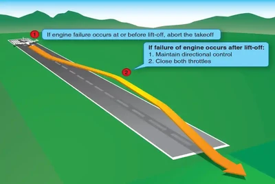
-
Landing Gear Down:
- If the engine failure occurs prior to selecting the landing gear to the UP position: Keep the nose as straight as possible, close both throttles, adjust pitch attitude to maintain adequate airspeed, and descend to the runway. []
- By raising landing gear only when there is no longer available runway to land as part of a takeoff and climb procedure, this decision point is made easy.
- Concentrate on a normal landing and do not force the aircraft on the ground.
- Depending upon how quickly the pilot reacts to the sudden yaw, the airplane may run off the side of the runway by the time action is taken.
- The chances of maintaining directional control while retracting the flaps (if extended), landing gear, feathering the propeller, and accelerating are minimal.
- On some airplanes with a single-engine-driven hydraulic pump, failure of that engine means the only way to raise the landing gear is to allow the engine to windmill or to use a hand pump.
- This is not a viable alternative during takeoff.
- If the engine failure occurs prior to selecting the landing gear to the UP position: Keep the nose as straight as possible, close both throttles, adjust pitch attitude to maintain adequate airspeed, and descend to the runway. []
-
Landing Gear Control Selected Up, Single-Engine Climb Performance Inadequate:
- When operating near or above the single-engine ceiling and an engine failure is experienced shortly after lift-off, a landing needs to be accomplished on whatever lies ahead. []
- In a descent at VYSE with the remaining engine producing power, as long as the pilot remains within the airplane's performance capability.
- Remaining airborne and bleeding off airspeed in a futile attempt to maintain altitude is almost invariably fatal.
- Landing under control is paramount.
- The greatest hazard in a single-engine takeoff is attempting to fly when it is not within the performance capability of the airplane to do so.
- Analysis of engine failures on takeoff reveals a very high success rate of off-airport engine inoperative landings when the airplane is landed under control.
- Analysis also reveals a very high fatality rate in stall spin accidents when the pilot attempts flight beyond the performance capability of the airplane.
- If the airplane's landing gear retraction mechanism is dependent upon hydraulic pressure from a certain engine-driven pump, failure of that engine can mean a loss of hundreds of feet of altitude as the pilot either windmills the engine to provide hydraulic pressure to raise the gear or raises it manually with a backup pump.
-
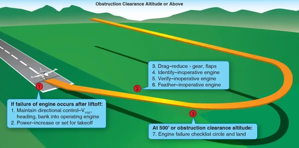
Landing Gear Control Selected Up, Single-Engine Climb Performance Adequate:
- If the single-engine rate of climb is adequate, the procedures for continued flight should be followed. []
- There are four areas of concern:
- Control;
- Configuration;
- Climb, and;
- Checklist.
-
Control:
- Maintaining directional control with prompt and often aggressive rudder application and STOPPING THE YAW is critical to the safety of flight.
- Ensure that airspeed stays above VMC.
- If the yaw cannot be controlled with full rudder applied, reducing thrust on the operative engine is the only alternative.
- Attempting to correct the roll with aileron without first applying rudder increases drag and adverse yaw and further degrades directional control.
- After rudder is applied to stop the yaw, a slight amount of aileron should be used to bank the airplane toward the operative engine.
- This is the most efficient way to control the aircraft, minimize drag, and gain the most performance.
- The pitch attitude for VYSE has to be lowered from that of VY.
- At least 5° and a maximum of 10° of bank toward the operative engine should be used initially to stop the yaw and maintain directional control.
- This initial bank input is held only momentarily, just long enough to establish or ensure directional control.
- Climb performance suffers when bank angles exceed approximately 2 or 3°, but obtaining and maintaining VYSE and directional control are paramount. Trim should be adjusted to lower the control forces.
- Maintaining directional control with prompt and often aggressive rudder application and STOPPING THE YAW is critical to the safety of flight.
-
Configuration:
- The memory items from the engine failure after takeoff checklist should be promptly executed to configure the airplane for climb. [Figure 13-21].
- The specific procedures to follow are found in the AFM/POH and checklist for the particular airplane.
- Most direct the pilot to assume VYSE, set takeoff power, retract the flaps and landing gear, identify, verify, and feather the failed engine while on some airplanes, the landing gear is to be retracted before the flaps.
- The "identify" step is for the pilot to initially identify the failed engine.
- Confirmation on the engine gauges may or may not be possible, depending upon the failure mode.
- Identification should be primarily through the control inputs required to maintain straight flight, not the engine gauges.
- The "verify" step directs the pilot to retard the throttle of the engine thought to have failed.
- No change in performance when the suspected throttle is retarded is verification that the correct engine has been identified as failed.
- The corresponding propeller control should be brought fully aft to feather the engine.
- The memory items from the engine failure after takeoff checklist should be promptly executed to configure the airplane for climb. [Figure 13-21].
-
Climb:
- As soon as directional control is established and the airplane configured for climb, the bank angle should be reduced to that producing best climb performance.
- Without specific guidance for zero sideslip, a bank of 2° and one-third to one-half ball deflection on the slip/skid indicator toward the operative engine is suggested.
- VYSE is maintained with pitch control.
- As turning flight reduces climb performance, climb should be made straight ahead or with shallow turns to avoid obstacles to an altitude of at least 400 feet AGL before attempting a return to the airport.
-
Checklist:
- Having accomplished the memory items from the engine failure after takeoff checklist, the printed copy should be reviewed as time permits.
- The securing failed engine checklist should then be accomplished. [Figure 13-22].
- Unless the pilot suspects an engine fire, the remaining items should be accomplished deliberately and without undue haste.
- Airplane control should never be sacrificed to execute the remaining checklists. The priority items have already been accomplished from memory.
- Other than closing the cowl flap of the failed engine, none of these items, if left undone, adversely affect airplane climb performance.
- There is a distinct possibility of actuating an incorrect switch or control if the procedure is rushed.
- The pilot should concentrate on flying the airplane and extracting maximum performance.
- If an ATC facility is available, an emergency should be declared.
- The memory items in the engine failure after takeoff checklist may be redundant with the airplane's existing configuration.
- For example, in the third takeoff scenario, the gear and flaps were assumed to already be retracted, yet the memory items included gear and flaps.
- This is not an oversight-The purpose of the memory items is to either initiate the appropriate action or to confirm that a condition exists.
- Action on each item may not be required in all cases. The memory items also apply to more than one circumstance.
- In an engine failure from a go-around, for example, the landing gear and flaps would likely be extended when the failure occurred.
- The three preceding takeoff scenarios all include the landing gear as a key element in the decision to land or continue.
- With the landing gear selector in the DOWN position, for example, continued takeoff and climb is not recommended. This situation, however, is not justification to retract the landing gear the moment the airplane lifts off the surface on takeoff as a normal procedure. The landing gear should remain selected down as long as there is usable runway or overrun available to land on. The use of wing flaps for takeoff virtually eliminates the likelihood of a single-engine climb until the flaps are retracted.
- There are two time-tested memory aids the pilot may find useful in dealing with engine-out scenarios. The first, "dead foot—dead engine" is used to assist in identifying the failed engine. Depending on the failure mode, the pilot will not be able to consistently identify the failed engine in a timely manner from the engine gauges. In maintaining directional control, however, rudder pressure is exerted on the side (left or right) of the airplane with the operating engine. Thus, the "dead foot" is on the same side as the "dead engine." Variations on this saying include "idle foot—idle engine" and "working foot–working engine."
- The second memory aid has to do with climb performance. The phrase "raise the dead" is a reminder that the best climb performance is obtained with a very shallow bank, about 2° toward the operating engine. Therefore, the inoperative, or "dead" engine should be "raised" with a very slight bank.
- Not all engine failures result in complete power loss. If there is a performance loss when the throttle of the affected engine is retarded, some power is still available. In this case, the pilot may consider allowing the engine to run until the airplane reaches a safe altitude and airspeed for single-engine flight. While shutdown of a malfunctioning engine may prevent additional damage to the engine in certain circumstances, shutting down an engine that can still produce partial power may increase risk for an accident.
- Having accomplished the memory items from the engine failure after takeoff checklist, the printed copy should be reviewed as time permits.
- In OEI flight at low altitudes and airspeeds such as the initial climb after takeoff, pilots should operate the airplane so as to guard against the three major accident factors:


Multi-Engine Specific Airspeeds
- Twin-engine airplanes have several additional V-speeds unique to OEI operation.
- Vxse: best angle-of-climb speed with one-engine inoperative.
- Vyse: best rate-of-climb speed with one-engine inoperative.
- Marked with a blue radial line on most airspeed indicators. []
- Above the single-engine absolute ceiling, VYSE yields the minimum rate of sink.
- VSSE: safe, intentional OIE speed.
- This is the minimum speed to intentionally render the critical engine inoperative.
- VMC: minimum controllable airspeed
- Currently defined in 14 CFR part 23, section 23.2135(c) as the calibrated airspeed at which, following the sudden critical loss of thrust, it is possible to maintain control of the airplane.
- VMC is typically marked with a red radial line on most airspeed indicators. []
- There is no requirement that the airplane be capable of climbing at this airspeed-VMC only addresses directional control.
Propeller Synchronization
- Having two propellers can produce a resonance that is felt in the cabin
- To eliminate this resonance, aircraft propellers must be synchronized.
- Prop synchronizing can be automatic, or require manual adjustment
- Many multiengine airplanes have a propeller synchronizer (prop sync).
- To use prop sync, the propeller rpms are coarsely matched by the pilot and the system is engaged.
- The prop sync adjusts the rpm of the "slave" engine to precisely match the rpm of the "master" engine and then maintains that relationship.
- The prop sync should be disengaged when the pilot selects a new propeller rpm and then re-engaged after the new rpm is set.
- The prop sync should always be off for takeoff, landing, and single-engine operation.
- A variation on the propeller synchronizer is the propeller synchrophaser.
- A propeller synchrophaser acts much like a synchronizer to precisely match rpm, but the synchrophaser goes one step further.
- It not only matches rpm but actually compares and adjusts the positions of the individual blades of the propellers in their arcs.
- There can be significant propeller noise and vibration reductions with a propeller synchrophaser.
- From the pilot's perspective, operation of a propeller synchronizer and a propeller synchrophaser are very similar.
- A synchrophaser is also commonly referred to as prop sync, although that is not entirely correct nomenclature from a technical standpoint.
- As a pilot aid to manually synchronizing the propellers, some twins have a small gauge mounted in or by the tachometer(s) with a propeller symbol on a disk that spins.
- The pilot manually fine tunes the engine rpm so as to stop disk rotation, thereby synchronizing the propellers.
- This is a useful backup to synchronizing engine rpm using the audible propeller beat.
- This gauge is also found installed with most propeller synchronizer and synchrophase systems. Some synchrophase systems use a knob for the pilot to control the phase angle.
Complex Set ups
- Multi engine aircraft usually incorporate high performance and complex configurations
-
Fuel Crossfeed:
- Fuel crossfeed systems are also unique to multiengine airplanes.
- Using crossfeed, an engine can draw fuel from a fuel tank located in the opposite wing.
- Learn more about fuel crossfeeding on the aviation fuel page.
- Fuel crossfeed systems are also unique to multiengine airplanes.
-
Combustion Heaters:
- Combustion heaters are another common device on multi-engine airplanes, not found on single-engine airplanes.
- Combustion heaters are a small furnace that burns gasoline to produce heated air for the occupant and other systems like windshield defogging.
- Learn more about combustion heaters on the environmental control page.
-
Flight Director/Autopilot:
- Multiengine airplanes are often equipped with flight director/autopilot (FD/AP) systems.
- The system integrates pitch, roll, heading, altitude, and radio navigation signals in a computer.
- Learn more about flight directors/autopilots on the flight management and autopilot systems page.
-
Yaw Dampener:
- The yaw damper is a servo that moves the rudder in response to inputs from a gyroscope or accelerometer that detects yaw rate or lateral Gs, respectively.
- The yaw damper reduces motion about the vertical axis caused by turbulence.
- Learn more about yaw dapeners on the flight control systems page.
-
Redundancy in Systems:
- Alternator/Generators:
- Dual-systems allow for isolation of the inoperative equipment and using the operating equipment to run all or some of the electrical system.
- Learn more about alternators/generators on the electrical systems page.
- Alternator/Generators:
Multiengine Transition
- Flight training in a multiengine airplane can be safely accomplished if both the instructor and the learner consider the following factors:
- The participants should conduct a preflight briefing of the objectives, maneuvers, expected learner actions, and completion standards before the flight begins.
- A clear understanding exists as to how simulated emergencies will be introduced, and what action the learner is expected to take.
- The introduction, practice, and testing of emergency procedures has always been a sensitive subject.
- Surprising a multiengine learner with an emergency without a thorough briefing beforehand creates a hazardous condition.
- Simulated engine failures, for example, can very quickly become actual emergencies or lead to loss of the airplane when approached carelessly.
- Stall-spin accidents in training for emergencies rival the number of stall-spin accidents from actual emergencies.
- The training risk normally gets mitigated by a briefing.
- Pulling circuit breakers is not recommended for training purposes and can lead to a subsequent gear up landing.
- Many normal, abnormal, and emergency procedures can be introduced and practiced in the airplane as it sits on the ground without the engines running.
- In this respect, the airplane is used as a procedures trainer. The value of this training may be substantial.
- The engines do not have to be operating for real learning to occur.
- Upon completion of a training session, care should be taken to restore items to their proper positions.
- Pilots who do not use a checklist effectively will be at a significant disadvantage in multiengine airplanes. Use of the checklist is essential to safe operation of airplanes, and it is risky to conduct a flight without one.
- The manufacturer's checklist or an aftermarket checklist that conforms to the manufacturer's procedures for the specific make, model, and model year may be used.
- If there is a procedural discrepancy between the checklist and the AFM/POH, then the AFM/POH always takes precedence.
- Certain immediate action items (such as a response to an engine failure in a critical phase of flight) are best committed to memory.
- After they are accomplished, and as work load permits, the pilot can compare the action taken with a checklist.
- Simulated engine failures during the takeoff ground roll may be accomplished with the mixture control.
- The simulated failure should be introduced at a speed no greater than 50 percent of VMC.
- If a learner does not react promptly by retarding both throttles, the instructor can always pull the other mixture.
- The FAA recommends that all in-flight simulated engine failures below 3,000 feet AGL, be introduced with a smooth reduction of the throttle.
- Thus, the engine is kept running and is available for instant use, if necessary.
- Smooth throttle reduction avoids abusing the engine and possibly causing damage.
- Simulation of inflight engine failures below VSSE introduces a very high and unnecessary training risk.
- If the engines are equipped with dynamic crankshaft counterweights, it is essential to make throttle reductions for simulated failures smoothly.
- Other areas leading to dynamic counterweight damage include high rpm and low manifold pressure combinations, overboosting, and propeller feathering.
- Severe damage or repetitive abuse to counterweights will eventually lead to engine failure.
- Dynamic counterweights are found on larger, more complex engines—instructors may check with maintenance personnel or the engine manufacturer to determine if their airplane engines are so equipped.
- When an instructor simulates an engine failure, the learner should respond with the appropriate memory items and retard the appropriate propeller control toward the FEATHER position.
- Assuming zero thrust will be set, the instructor promptly moves the propeller control forward and sets the appropriate manifold pressure and rpm.
- It is vital that the learner be kept informed of the instructor's intentions.
- At this point the instructor may say words to the effect, "I have the right engine; you have the left.
- I have set zero thrust and the right engine is simulated feathered."
- Any ambiguity as to who is operating what systems or controls increases the likelihood of an unintended outcome.
- Following a simulated engine failure, the instructor cares for the "failed" engine just as the learner cares for the operative engine.
- If zero thrust is set to simulate a feathered propeller, the cowl flap is normally closed and the mixture leaned.
- An occasional clearing of the engine is also desirable.
- If possible, avoid high power applications immediately following a prolonged cool-down at a zero-thrust power setting.
- A competent flight instructor teaches the multiengine learner about the critical importance of feathering the propeller in a timely manner should an actual engine failure situation ever be encountered.
- A windmilling propeller, in many cases, has given the improperly trained multiengine pilot the mistaken perception that the engine is still developing useful thrust, resulting in a psychological reluctance to feather, as feathering results in cessation of propeller rotation.
- The flight instructor should spend ample time demonstrating the difference in the performance capabilities of the airplane with a simulated feathered propeller (zero thrust) as opposed to a windmilling propeller.
- Actual and safe propeller feathering for training is performed at altitudes and positions where safe landings on established airports may be readily accomplished if the propeller will not unfeather.
- Plan unfeathering and restart to be completed no lower than 3,000 feet AGL.
- At certain elevations and with many popular multiengine training airplanes, this may be above the single-engine service ceiling, and level flight will not be possible.
- Repeated feathering and unfeathering is hard on the engine and airframe, and is done as necessary to ensure adequate training.
- The FAA's Airman Certification Standards for a multiengine class rating contains a task for feathering and unfeathering of one propeller during flight in airplanes in which it is safe to do so.
- While much of this chapter has been devoted to the unique flight characteristics of a multiengine airplane with one engine inoperative, the modern well-maintained reciprocating engine is remarkably reliable.
- When training in an airplane, initiation of a simulated engine inoperative emergency at low altitude normally occurs at a minimum of 400 feet AGL to mitigate the risk involved and only after the learner has successfully mastered engine inoperative procedures at higher altitudes.
- Initiating a simulated low altitude engine inoperative emergency in the airplane at extremely low altitude, immediately after liftoff, or below VSSE creates a situation where there are non-existent safety margins.
- For training in maneuvers that would be hazardous in flight, or for initial and recurrent qualification in an advanced multiengine airplane, consider a simulator training center or manufacturer's training course.
- Comprehensive training manuals and classroom instruction are available along with system training aids, audio/visuals, and flight training devices and simulators.
- Training under a wide variety of environmental and aircraft conditions is available through simulation.
- Emergency procedures that would be either dangerous or impossible to accomplish in an airplane can be done safely and effectively in a flight training device or simulator.
- The flight training device or simulator need not necessarily duplicate the specific make and model of airplane to be useful.
- Highly effective instruction can be obtained in training devices for other makes and models as well as generic training devices.
- The majority of multiengine training is conducted in four-to-six place airplanes at weights significantly less than maximum. Singleengine performance, particularly, at low density altitudes, may be deceptively good.
- To experience the performance expected at higher weights, altitudes and temperatures, the instructor may occasionally artificially limit the amount of manifold pressure available on the operative engine.
- Airport operations above the single-engine ceiling can also be simulated in this matter.
- Avoid loading the airplane with passengers to practice emergencies at maximum takeoff weight since this practice creates an unnecessary training hazard.
- The use of the touch-and-go landing and takeoff in multiengine flight training has always been somewhat controversial.
- The value of the learning experience may be offset by the hazards of reconfiguring the airplane for takeoff in extremely limited time as well as the loss of the follow-through ordinarily experienced in a full stop landing.
- Touch-and-goes are not recommended during initial aircraft familiarization in multiengine airplanes.
- If touch-and-goes are to be performed at all, the learner and instructor responsibilities should be carefully briefed prior to each flight.
- Following touchdown, the learner will ordinarily maintain directional control while keeping the left hand on the yoke and the right hand on the throttles.
- The instructor resets the flaps and trim and announces when the airplane has been reconfigured.
- The multiengine airplane uses considerably more runway to perform a touch-and-go than a single-engine airplane.
- A full stop-taxi back landing is preferable during initial familiarization.
- Solo touch-and-goes in twins are strongly discouraged.
- The AOPA provides multi-engine transition resources.
Multiengine Operations Airman Certification Standards
-
Commercial Pilot (Airplane) Maneuvering with One Engine Inoperative (AMEL, AMES) Airman Certification Standards:
- Objective: To determine whether the applicant exhibits satisfactory knowledge, risk management, and skills associated with maneuvering with one engine inoperative.
- Note: See Appendix 2: Safety of Flight and Appendix 3: Aircraft, Equipment, and Operational Requirements & Limitations for information related to this Task.
- References: FAA-H-8083-2 (Risk Management Handbook), FAA-H-8083-3 (Airplane Flying Handbook), FAA-H-8083-25 (Pilot Handbook of Aeronautical Knowledge); FAA-P-8740-66; POH/AFM.
Commercial Pilot (Airplane) Maneuvering with One Engine Inoperative (AMEL, AMES) Knowledge:
The applicant demonstrates an understanding of:-
CA.X.A.K1:
Factors affecting minimum controllable speed (VMC). -
CA.X.A.K2:
VMC (red line) and best single-engine rate of climb airspeed (VYSE) (blue line). -
CA.X.A.K3:
How to identify, verify, feather, and secure an inoperative engine. -
CA.X.A.K4:
Importance of drag reduction, including propeller feathering, gear and flap retraction, the manufacturer's recommended control input and its relation to zero sideslip. -
CA.X.A.K5:
Feathering, securing, unfeathering, and restarting.
Commercial Pilot (Airplane) Maneuvering with One Engine Inoperative (AMEL, AMES) Risk Management:
The applicant is able to identify, assess, and mitigate risks associated with:-
CA.X.A.R1:
Potential engine failure during flight. -
CA.X.A.R2:
Collision hazards. -
CA.X.A.R3:
Configuring the airplane. -
CA.X.A.R4:
Low altitude maneuvering, including stall, spin, or controlled flight into terrain (CFIT). -
CA.X.A.R5:
Distractions, task prioritization, loss of situational awareness, or disorientation.
Commercial Pilot (Airplane) Maneuvering with One Engine Inoperative (AMEL, AMES) Skills:
The applicant exhibits the skills to:-
CA.X.A.S1:
Recognize an engine failure, maintain control, use manufacturer's memory item procedures, and use appropriate emergency procedures. -
CA.X.A.S2:
Set the engine controls, identify and verify the inoperative engine, and feather the appropriate propeller. -
CA.X.A.S3:
Use flight controls in the proper combination as recommended by the manufacturer, or as required to maintain best performance, and trim as required. -
CA.X.A.S4:
Attempt to determine and resolve the reason for the engine failure. -
CA.X.A.S5:
Secure the inoperative engine and monitor the operating engine and make necessary adjustments. -
CA.X.A.S6:
Restart the inoperative engine using manufacturer's restart procedures. -
CA.X.A.S7:
Maintain altitude ±100 feet or a minimum sink rate if applicable, airspeed ±10 knots, and selected headings ±10°. -
CA.X.A.S8:
Complete the appropriate checklist(s).
-
Commercial Pilot (Airplane) VMC Demonstration Airman Certification Standards:
- Objective: To determine whether the applicant exhibits satisfactory knowledge, risk management, and skills associated with VMC demonstration.
- Note: See Appendix 2: Safety of Flight and Appendix 3: Aircraft, Equipment, and Operational Requirements & Limitations for information related to this Task.
- References: FAA-H-8083-2 (Risk Management Handbook), FAA-H-8083-3 (Airplane Flying Handbook), FAA-H-8083-25 (Pilot Handbook of Aeronautical Knowledge); FAA-P-8740-66; POH/AFM.
Commercial Pilot (Airplane) VMC Demonstration Knowledge:
The applicant demonstrates an understanding of:-
CA.X.B.K1:
Factors affecting VMC and how VMC differs from stall speed (VS). -
CA.X.B.K2:
VMC (red line), VYSE (blue line), and VSSE (safe single-engine speed). -
CA.X.B.K3:
Cause of loss of directional control at airspeeds below VMC. -
CA.X.B.K4:
Proper procedures for maneuver entry and safe recovery.
Commercial Pilot (Airplane) VMC Demonstration Risk Management:
The applicant is able to identify, assess, and mitigate risks associated with:-
CA.X.B.R1:
Configuring the Airplane. -
CA.X.B.R2:
Maneuvering with one engine inoperative. -
CA.X.B.R3:
Distractions, task prioritization, loss of situational awareness, or disorientation.
Commercial Pilot (Airplane) VMC Demonstration Skills:
The applicant exhibits the skills to:-
CA.X.B.S1:
Configure the airplane in accordance with the manufacturer's recommendations, in the absence of the manufacturer's recommendations, then at safe single-engine speed (VSSE/VYSE), as appropriate, and:-
CA.X.B.S1a:
Landing gear retracted. -
CA.X.B.S1b:
Flaps set for takeoff. -
CA.X.B.S1c:
Cowl flaps set for takeoff. -
CA.X.B.S1d:
Trim set for takeoff. -
CA.X.B.S1e:
Propellers set for high revolutions per minute (rpm). -
CA.X.B.S1f:
Power on critical engine reduced to idle and propeller windmilling. -
CA.X.B.S1g:
Power on operating engine set to takeoff or maximum available power.
-
-
CA.X.B.S2:
Establish a single-engine climb attitude with the airspeed at approximately 10 knots above VSSE. -
CA.X.B.S3:
Establish a bank angle not to exceed 5° toward the operating engine, as required for best performance and controllability. -
CA.X.B.S4:
Increase the pitch attitude slowly to reduce the airspeed at approximately 1 knot per second while applying increased rudder pressure as needed to maintain directional control. -
CA.X.B.S5:
Recognize and recover at the first indication of loss of directional control, stall warning, or buffet. -
CA.X.B.S6:
Recover promptly by simultaneously reducing power sufficiently on the operating engine, decreasing the angle of attack as necessary to regain airspeed and directional control, and without adding power on the simulated failed engine. -
CA.X.B.S7:
Recover within 20° of entry heading. -
CA.X.B.S8:
Advance power smoothly on the operating engine and accelerate to VSSE/VYSE, as appropriate, ±5 knots during recovery.
Multiengine Operations Knowledge Check


Multiengine Operations Conclusion
- Multi-engine aircraft are great for carrying capacity, for larger families or when transporting payloads
- Note, VMC is the speed at which directional control can be maintained, but the aircraft may still lack the performance to climb or even maintain altitude.
- There are no specific numbers to hit on how far you must turn, etc. for a clearing turn to be acceptible
- It is, instead, pilot judgement on what is acceptable to call the area cleared
- As stated above, Multiengine Operations may need to be made to a specific direction for a reason however, consider Multiengine Operations to the left first
- This ensures that if anyone is passing to the right in accordance with right-of-way guidelines, you and them remain clear of one another
- Remain mindful that performance calculations are usually more optimistic than actual performance.
- See also: Visual Scanning and Collision Avoidance.
- Consider practicing maneuvers on a flight simulator to introduce yourself to maneuvers or knock off rust
- Still looking for something? Continue searching: