Aircraft Components & Structure
The airframe and its components are the foundation of aircraft design and control, interacting with aerodynamic forces and stresses imposed.
Introduction to Aircraft Components & Structure
- The airframe is the basic structure of an aircraft, designed to withstand aerodynamic forces and stresses imposed.
- Stresses include the weight of fuel, crew, and payload.
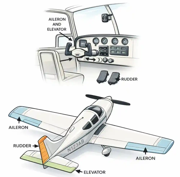
- The airplane is controllable around its lateral, longitudinal, and vertical axes by deflection of flight control surfaces.
- These control devices are hinged or movable surfaces that the pilot uses to adjust the airplane's attitude during takeoff, flight maneuvering, and landing.
- The pilot operates them by connecting the linkage using rudder pedals and a control stick or wheel.
- The fuselage is an aircraft's principal structural unit.
- Attached to the fuselage are the wings, the principal airfoil that produces lift.
- The empennage, located at the rear of the aircraft, supports the vertical and horizontal stabilizers.
- The stabilizers provide mounting surfaces for the rudder and elevator, and in some cases, they serve as both.
- Attached to the wings and stabilizers are an assortment of flight control surfaces:
- The primary flight controls consist of the ailerons, elevators, and rudders.
- The secondary flight controls consist of the movable trim tabs on the primary flight control surfaces.
- The auxiliary flight controls include wing flaps, spoilers, speed brakes, and slats.
Aircraft Components & Structure Key Highlights
- Aircraft structures are designed to withstand aerodynamic forces, weight, and stress during all phases of flight.
- The primary structural components include the fuselage, wings, empennage (tail), and landing gear.
- Wings generate lift through their airfoil shape and may be braced or cantilevered depending on design.
- The fuselage serves as the central body, connecting all major components and housing crew, passengers, and cargo.
- The empennage provides stability and control through horizontal and vertical stabilizers.
- Control surfaces—ailerons, elevator, and rudder—allow the pilot to control roll, pitch, and yaw.
- Secondary control surfaces, such as flaps and trim systems, enhance performance and reduce pilot workload.
- Aircraft construction types include truss, monocoque, and semi-monocoque, with semi-monocoque being the most common in modern aircraft.
- Loads acting on an aircraft include tension, compression, torsion, bending, and shear.
- Structural design distributes these loads safely throughout the airframe to maintain integrity and prevent failure.
Aircraft Fuselage Designs
- The fuselage is the principal structural unit of an aircraft, designed to accommodate the crew, passengers, cargo, instruments, and other essential equipment.
-
Types of Fuselage Construction:
- The construction of aircraft fuselages has evolved from early wood truss structural arrangements to monocoque shell structures, and now to the modern semi-monocoque shell structures.
- Most modern aircraft use a form of a stressed skin structure known as monocoque or semi-monocoque construction.
-
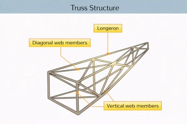
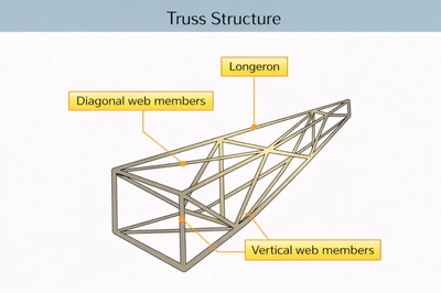
Truss Structure:
- In this construction method, joined tubing (typically steel or aluminum) produces a series of triangular shapes called trusses, which provide the structure with strength and rigidity. []
- Lengths of tubing, called longerons, are welded in place to form a well-braced framework.
- Vertical and horizontal struts are welded to the longerons, giving the structure a square or rectangular shape when viewed from the end.
- Additional struts are needed to resist stress that can come from any direction.
- Stringers and bulkheads, also known as formers, are added to shape the fuselage and provide support for the covering.
- These structures were enclosed as designs progressed, first with cloth and eventually with metals.
- These upgrades streamlined shape and increased performance.
- In some cases, the outside skin can support all or a significant portion of the flight loads.
- The 1903 Wright Flyer is an iconic example of the truss design.
- In this construction method, joined tubing (typically steel or aluminum) produces a series of triangular shapes called trusses, which provide the structure with strength and rigidity. []
-
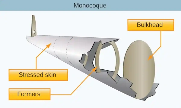
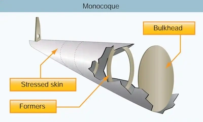
Monocoque Structure:
- Monocoque (French for "single shell") construction uses stressed skin to support almost all loads, much like an aluminum beverage can.
- In monocoque construction, rigs, formers, and bulkheads of varying sizes give shape and strength to the stressed skin fuselage. []
- Although very strong, monocoque construction is not highly tolerant of surface deformation.
- For example, an aluminum beverage can can withstand considerable forces at its ends until the side is deformed slightly.
- Once deformed, it easily collapses under load.
- Carrying twisting and bending stresses across the skin rather than an open framework eliminates or reduces the need for internal bracing, saving weight and maximizing space.
- Jack Northrop employed one of the notable and innovative methods for using monocoque construction.
- In 1918, he developed a new method for constructing a monocoque fuselage, which he later applied in the Lockheed S-1 Racer.
- The technique utilized two molded plywood half-shells glued together around wooden hoops or stringers.
- Rather than gluing many plywood strips over a form, Northrop soaked three large sets of spruce strips with glue and laid them in a semi-circular concrete mold that resembled a bathtub.
- Then, under a tightly clamped lid, a rubber balloon was inflated in the cavity to press the plywood against the mold.
- Twenty-four hours later, the smooth half-shell was ready to be joined to another to create the fuselage.
- The two halves were each less than a quarter of an inch thick.
- Although employed early in aviation, monocoque construction would not reemerge for several decades due to its complexities.
- Everyday examples of monocoque construction can be found in automobile manufacturing, where the unibody is considered standard.
- The Deperdussin Racer is an example of the monocoque design.
-
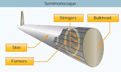
Semi-monocoque Structure:
- Semi-monocoque construction, partial or one-half, uses a substructure to which the airplane's skin is attached.
- The substructure, consisting of bulkheads, formers of various sizes, and stringers, reinforces the stressed skin by removing bending stress from the fuselage.
- The main section of the fuselage also includes wing attachment points and a firewall.
- On single-engine airplanes, manufacturers usually attach the engine to the front of the fuselage.
- A fireproof partition (firewall) separates the rear of the engine from the flight deck or cabin, protecting the pilot and passengers from accidental engine fires.
- A heat-resistant material, such as stainless steel, comprises this partition, known as a firewall.
- However, a new emerging construction process is the integration of composites, such as those used in aircraft, which are made entirely of composites. []
- Semi-monocoque designs are the most prevalent, with their use ranging from the Douglas DC-3 to the Boeing 747.

Aircraft Wings
- Wings are airfoils attached to each side of the fuselage and are the main lifting surfaces that support the airplane in flight.
- Wings may be attached at the top ("high-wing"), middle ("mid-wing"), or lower ("low-wing") portion of the fuselage.
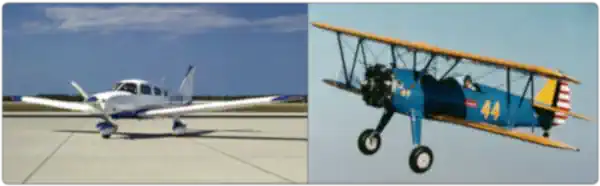
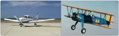
- Airplanes with a single set of wings are monoplanes, while those with two sets are biplanes. []
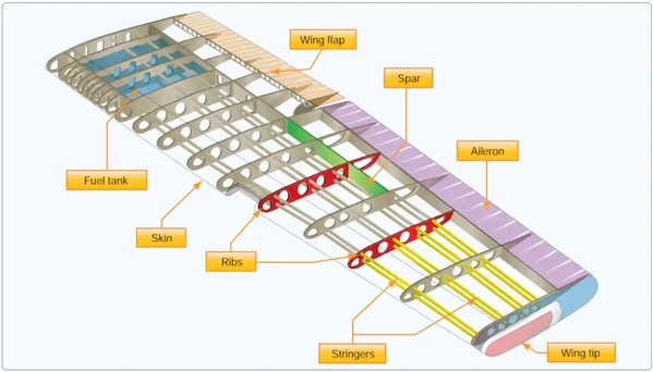
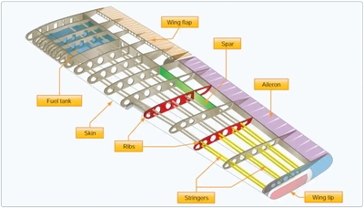
- The principal structural parts of the wing are spars, ribs, and stringers. []
- Trusses, I-beams, tubing, or other devices, including the skin, reinforce these.
- The wing ribs determine the shape and thickness of the wing (airfoil).
- In most modern airplanes, the fuel tanks are either an integral part of the wing's structure or consist of flexible containers mounted inside the wing.
- Two control surfaces, ailerons and flaps, are attached to the wings' rear or trailing edges.
-
Alternate Types of Wings:
- Design variations provide information on the effects controls have on lifting surfaces, ranging from traditional wings to those that use both flexing (due to billowing) and shifting (through changes in the aircraft's CG).
- For example, manufacturers sweep aircraft wings sharply on weight-shift control aircraft to reduce drag and enable weight shifting for controlled flight.
- The Federal Aviation Administration (FAA) website provides handbooks specific to most aircraft categories for interested pilots.
- Design variations provide information on the effects controls have on lifting surfaces, ranging from traditional wings to those that use both flexing (due to billowing) and shifting (through changes in the aircraft's CG).
-
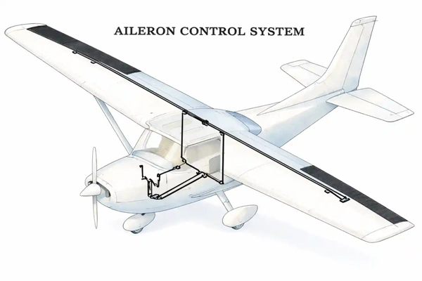
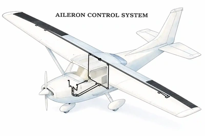
Ailerons:
- Ailerons (French for "little wing") are control surfaces on each wing that move the aircraft about its longitudinal axis, allowing it to "roll" or "bank."
- Aileron functionality details are below.
-
Wing Planform:
- A wing's shape and design depend on the intended type of operation. []
-
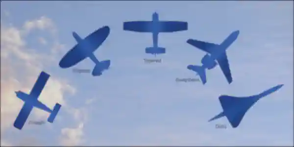
Rectangular Wings:
- Rectangular wings are best for both training and low-speed aircraft.
- Rectangular wings feature an aerodynamic twist, which lowers the angle of attack at the wing tips and protects aileron control in the event of a stall.
- Therefore, if the aircraft stalls, it does so first at the wing root.
-
Elliptical Wings:
- Elliptical wings are the most efficient but difficult to produce (Spitfire).
-
Tapered Wings:
- Tapered wings are more efficient than rectangular wings but easier to produce than an elliptical design.
-
Swept Wings:
- Swept wings are most often thought of as swept-back, but can also be swept-forward.
- Swept-back wing designs are best for high-speed aircraft to delay the onset of Mach effects.
- Swept wings stall at the tips first, leading to poor stall characteristics.
- A swept wing with a large dihedral effect increases dutch roll tendencies.
-
Delta Wings:
- A delta wing's advantages include good structural efficiency and a low frontal area.
- A delta-wing's disadvantages include its low wing loading and the high wetted area required for aerodynamic stability.
-
- A wing's shape and design depend on the intended type of operation. []
-
Wing Mounting:
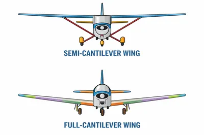
- Wings of most general aviation aircraft are cantilever or semi-cantilever mounted. []
- Many high-wing airplanes have external braces, or wing struts, that transmit flight and landing loads from the wings to the main fuselage structure.
- Since the wing struts are usually attached approximately halfway out on the wing, this type of wing structure is called a semi-cantilever.
- The semi-cantilever wings require external bracing, which is accomplished by attaching wing struts to the fuselage and internally bracing them with spars and ribs.
- A few high-wing and most low-wing airplanes have full cantilever wings designed to carry loads without external bracing; internal wing spars, ribs, and stringers carry the stress.
- Generally, the "skin" or metal wing covering carries much of the wing stresses.
- Wings of most general aviation aircraft are cantilever or semi-cantilever mounted. []


Aircraft Empennages
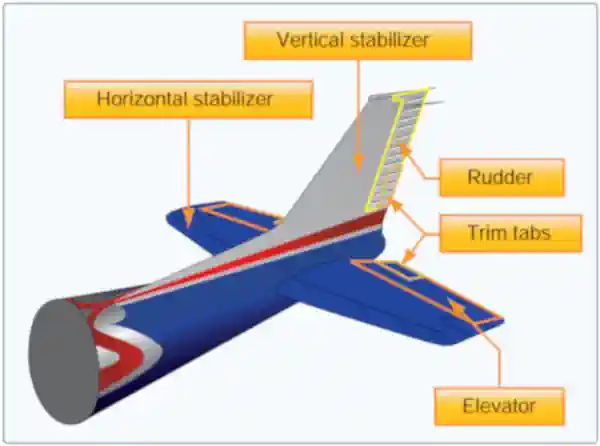
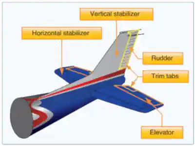
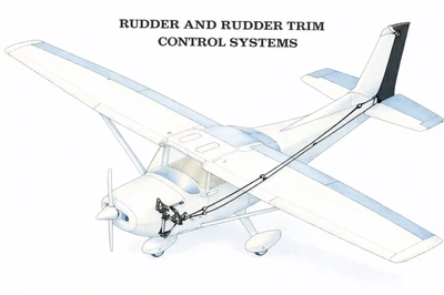
- Commonly known as the "tail section," the empennage includes the entire tail group, which consists of fixed surfaces such as the vertical fin or stabilizer and the horizontal stabilizer; the movable surfaces, including the rudder and rudder trim tabs, as well as the elevator and elevator trim tabs. []
- The pilot uses these movable surfaces to control the airplane's horizontal (yaw) and vertical (pitch) rotation.
- In some airplanes, the entire horizontal stabilizer surface of the empennage is adjustable from the cockpit as a complete unit to control the airplane's pitch attitude or trim.
- Such designs are called stabilators, flying tails, or slab tails.
- The empennage, then, provides the aircraft with directional and longitudinal balance (stability) and allows the pilot to control and maneuver it.
-
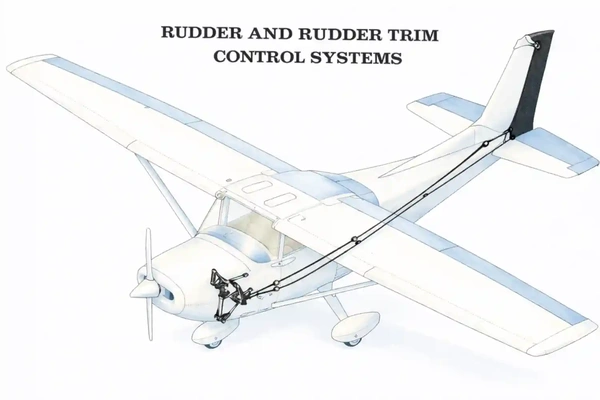
Rudder:
- Rudders control the direction (left or right) of "yaw" about an airplane's vertical axis.
- Rudder functionality details are below.
-
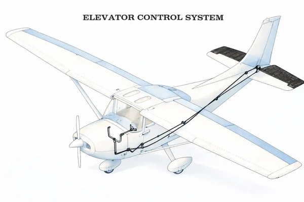
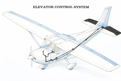
Elevator:
- The elevator, attached to the back of the horizontal stabilizer, moves the nose of the airplane up and down during flight.
- Elevator functionality details are below.
-
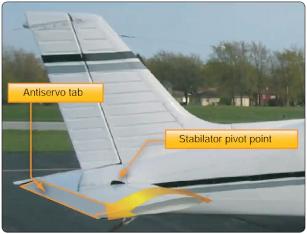
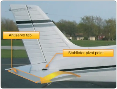
Stabilator:
- A second type of empennage design does not require an elevator.
- Instead, it incorporates a one-piece horizontal stabilizer that pivots from a central hinge point.
- This type of design is called a stabilator, controlled using the control wheel, much like an elevator. []
- The change in aerodynamic tail load causes the airplane's nose to move up or down.
- When a pilot pulls back on the control wheel, the stabilator pivots, causing the trailing edge to move upward.
- When a pilot pushes forward on the control wheel, the stabilator pivots, causing the trailing edge to move downward.
Flight Control Surfaces
- Flight control surfaces consist of primary, secondary, and auxiliary controls. []
-
Primary Flight Controls:
-
Ailerons:
- Ailerons (French for "little wing") are control surfaces on each wing that move the aircraft about its longitudinal axis, allowing it to "roll" or "bank.". []
- This action results in the airplane turning toward the roll/bank.
- With aileron deflection, there is an asymmetrical lift (rolling moment) about the longitudinal axis and drag (adverse yaw).
- They mount on each wing's trailing (rear) edge near the outer tips.
- They extend from about the midpoint of each wing outward toward the tip and move in opposite directions, creating aerodynamic forces that cause the airplane to roll.
- The yoke manipulates the airfoil through cables and pulleys, acting in an opposing manner.
- The yoke "turns" left: the left aileron rises, decreasing the camber and angle of attack on the right wing, which creates a downward lift.
- At the same time, the right aileron lowers, increasing the camber and angle of attack on the right wing, which increases upward lift and causes the aircraft to turn left.
- The yoke "turns" right: the right aileron rises, decreasing the camber and angle of attack on the right wing, which creates a downward lift.
- At the same time, the left aileron lowers, increasing the camber and angle of attack on the left wing, which decreases upward lift and causes the aircraft to turn right.
- The yoke "turns" left: the left aileron rises, decreasing the camber and angle of attack on the right wing, which creates a downward lift.
- Although uncommon for general aviation aircraft, some ailerons are configured with trim tabs, which relieve pressure on the yoke and the aileron.
- Ailerons (French for "little wing") are control surfaces on each wing that move the aircraft about its longitudinal axis, allowing it to "roll" or "bank.". []
-
Rudder:
- Rudders control the direction (left or right) of "yaw" about an airplane's vertical axis. []
- Like the other primary control surfaces, the rudder is a movable surface hinged to a fixed surface, in this case, the vertical stabilizer, also known as the fin.
- Its action is similar to that of elevators, except it swings in a different plane, from side to side, instead of up and down.
- Rudders do not turn the airplane left and right, as is often erroneously believed.
- In practice, coordinated aileron and rudder control inputs turn an aircraft, the ailerons imparting roll.
- This relationship is critical in maintaining coordination.
- Improperly ruddered turns can produce a skid or slip.
- Improperly ruddered turns at low speed can precipitate a spin.
- The pilot controls the rudders with their feet through a system of cables and pulleys:
- "Step" on the right rudder pedal: the rudder moves right, creating a yaw to the right.
- "Step" on the left rudder pedal: the rudder moves left, creating a yaw to the left.
-
Yaw Dampener:
- The yaw damper is a servo that moves the rudder in response to inputs from a gyroscope or accelerometer, which detect yaw rate or lateral Gs, respectively.
- The yaw damper reduces motion about the vertical axis caused by turbulence.
- Yaw dampers on swept-wing airplanes provide another, more vital function of damping Dutch roll characteristics.
- Occupants experience a smoother ride, particularly when seated in the rear of the aircraft, with the yaw damper engaged.
- The yaw damper should be off for takeoff and landing.
- There may be additional restrictions on its use when one engine is inoperative (for multi-engine aircraft).
- Pilots can engage most yaw dampers independently of the autopilot.
-
Water Rudders:
- Water rudders are similar to boat rudders, which can assist in steering an aircraft when it is on floats.
-
Elevator:
- The elevator, attached to the back of the horizontal stabilizer, moves the nose of the airplane up and down during flight. []
- Elevators are control surfaces that control the aircraft about its lateral axis, allowing the aircraft to pitch.
- The elevators are attached to the horizontal portion of the empennage - the horizontal stabilizer.
- A stabilator is an exception.
- A change in the elevator's position alters the camber of the airfoil, thereby increasing or decreasing lift.
- When applying forward pressure to the controls, the elevators move downward, increasing the lift produced by the horizontal tail surfaces.
- The increased lift forces the tail upward, causing the nose to drop.
- Conversely, when applying back pressure to the wheel, the elevators move upward, decreasing the lift produced by the horizontal tail surfaces and creating a downward force.
- The decreased lift forces the tail downward, causing the nose to rise.
- The elevators control the angle of attack of the wings.
- When applying back pressure on the controls, the tail lowers, and the nose rises, increasing the angle of attack.
- Conversely, when applying forward pressure, the tail raises, and the nose lowers, decreasing the angle of attack.
- Stabilizer: a control surface other than the wings that provides stabilizing qualities.
-
-
Secondary Flight Controls:
- Secondary flight controls consist of the trim tabs.
- Tabs are small, adjustable aerodynamic devices on the trailing edge of the control surface.
- These movable surfaces reduce pressure on the controls.
- Trim controls a neutral point, like balancing the aircraft on a pin with unsymmetrical weights.
- Trimming is performed either by adjusting the trim tabs (small movable surfaces on the control surface) or by shifting the neutral position of the entire control surface.
- Ailerons, rudders, and/or elevators may all have tabs installed.
-
Trim Tabs:
- Trim tabs are movable devices located on the primary control surfaces, specifically the ailerons, elevators, and rudder.
- These reduce the pilot's workload, enabling the aircraft to hold a particular attitude without needing constant pressure/inputs into the system.
- The force of the airflow striking the tab causes the main control surface to deflect to a position that corrects the unbalanced condition of the aircraft.
- When disturbed, a properly trimmed aircraft will return to its previous state due to its inherent stability.
- Trimming is a constant task required after any change in power setting, airspeed, altitude, or configuration.
- Proper trimming decreases pilot workload, allowing for focus elsewhere, which is especially important for instrument flying.
- A system of cables and pulleys controls the trim tabs.
- Trim tab adjusted up: The trim tab lowers, creating positive lift and lowering the nose.
- This movement is very slight.
- Trim tab adjusted down: The trim tab raises, creating positive lift and raising the nose.
- This movement is very slight.
- Trim tab adjusted up: The trim tab lowers, creating positive lift and lowering the nose.
- To learn more about how to use the trim tab in flight, see the trimming of the aircraft.
- Trim tabs are movable devices located on the primary control surfaces, specifically the ailerons, elevators, and rudder.
-
Servo Tabs:
- Servo tabs are similar to trim tabs in that they are small secondary controls that help reduce pilot workload by reducing forces.
- The defining difference, however, is that these tabs operate automatically, independent of the pilot.
-
Anti-servo:
- Also known as an anti-balance tab, this tab moves in the same direction as the trailing edge of the stabilator, helping to reduce the stabilator's sensitivity to yaw.
- The anti-servo tab also functions as a trim tab, relieving control pressures and helping to maintain the stabilator in its desired position.
-
Servo:
- Tabs that move in the opposite direction from the control surface.
-
Auxiliary Flight Controls:
- Auxiliary flight control surfaces consist of flaps and slats.
-
Flaps:
- Flaps are part of the Flight Control System.
- Flaps are attached to the trailing edge of the wings and controlled by the pilot from the cockpit.
- Flaps are primarily used for operations at slower airspeeds, typically during takeoff and landing.
- Slats and flaps are used in conjunction with each other to increase both lift and stall margin by increasing the overall wing camber, thus allowing the aircraft to maintain control of flight at slower airspeeds.
- Flaps extend outward from the fuselage to near the midpoint of each wing.
- The flaps are generally flush with the wing's surface during cruising flight.
- When extended, the flaps move simultaneously downward to increase the lifting force of the wing for takeoffs and landings.
-
Slats:
- Slats are part of the Flight Control System, creating extra lift during lower speeds.
- They are attached to the leading edge of the wings and are designed to be controlled by the pilot or automatically by the flight computer.
- Slats increase the camber of the wings/airfoil.
- When the aircraft is at slower airspeeds, typically on takeoff and landing, extending the slats creates additional lift.

Other Aircraft Components
-
Windscreen:
- Don't forget to clean the windscreen.
-
Speed Brakes:
- Speed brakes disrupt airflow and increase parasitic drag, allowing the pilot to slow the aircraft in a dive or descent.
- Location and style vary with aircraft.
-
Landing Gear:
- The landing gear is the principal support of the airplane when parked, taxiing, taking off, or landing.
- A steerable nosewheel or tailwheel permits the airplane to be controlled throughout all operations while on the ground.
- Most aircraft steer by moving the rudder pedals, whether nosewheel or tailwheel, while some aircraft steer by differential braking.
-
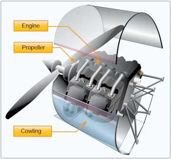
Power Plant:
- The powerplant usually includes both the engine and the propeller.
-
Engine:
- The engine's primary function is to provide the power to turn the propeller.
- In jet aircraft, the engine transfers power without a propeller.
- It also generates electrical power, provides a vacuum source for some flight instruments, and, in most single-engine airplanes, provides a source of heat for the pilot and passengers. []
- The engine mounts at the front of the fuselage on most single-engine airplanes.
- A fireproof partition, commonly referred to as a firewall, is typically made of highly heat-resistant stainless steel and is located between the rear of the engine and the cockpit or cabin to protect the pilot and passengers from accidental engine fires.
- The engine's primary function is to provide the power to turn the propeller.
-
Cowling:
- A cowling or a nacelle provides a covered housing for the engine.
- The cowling, or nacelle, streamlines airflow around the engine and helps cool it by directing air around the cylinders.
-
Propeller:
- The propeller, mounted on the front of the engine, converts the rotating force of the engine into thrust, a forward-acting force that helps propel the airplane through the air.
- A propeller is a rotating airfoil that produces thrust through aerodynamic action.
- A high-pressure area forms at the back of the propeller's airfoil, while a low-pressure area forms at the face of the propeller, similar to the lift generation by an airfoil, such as a wing.
- This pressure differential develops thrust from the propeller, pulling the airplane forward.
- Just as propellers can pull, they can also push when mounted on the back of an aircraft.
- Propeller angle and pitch are two significant factors that impact the design of a propeller's effectiveness.
- Propeller Angle:
- The angle of a propeller blade, as measured against the propeller's hub, keeps the angle of attack (AOA) (See definition in Glossary) relatively constant along the span of the propeller blade, reducing or eliminating the possibility of a stall.
- The amount of lift produced by the propeller is directly related to the AOA, which is the angle at which the relative wind meets the blade.
- The AOA continuously changes during the flight depending on the aircraft's direction.
- Propeller Pitch:
- The pitch is the distance a propeller would travel in one revolution if turning in a solid.
- These two factors combine to allow a measurement of the propeller's efficiency.
- Matching propellers to a specific aircraft/powerplant combination achieves the best efficiency at a particular power setting, and they pull or push depending on how the engine is mounted.
- Propeller Angle:

Rotary-Wing Components
- The significant difference between helicopters and fixed-wing aircraft is the source of lift.
- Fixed-wing aircraft derive lift from fixed airfoils, while helicopters use rotating airfoils known as rotor blades.
- Lift and control are relatively independent of forward speed.
-
Rotary-Wing Controls:
-
Cyclic Stick:
- Controls movement about the lateral and longitudinal axes of the helicopter.
- It is centered in front of the pilot's seat and changes the tip path plane of the main rotor for directional flight.
- Changing the tip path plane alters the direction of thrust and the corresponding intended direction of movement or flight.
-
Collective Stick:
- The collective is located to the left of the pilot's seat and varies the lift of the main rotor by decreasing or increasing the angle of attack on all rotor plates equally and in the same direction.
- The pilot uses the collective and cyclic combination to regulate the aircraft's speed and altitude.
-
Rudder Pedals:
- Controls movement about the vertical axis (yaw) of the helicopter by changing the pitch (angle of attack) of the tail rotor plates.
- The pedals cause the tail rotor to develop more or less force, counteracting the torque caused by the main rotors.
- Additionally, the pilot can deflect the rudder pedals left or right to change the aircraft's heading or direction.
-
-
Components:
-
Rotor Blade:
- Spinning "wings" that allow for lift in helicopters or "rotor-craft."
-
Main Rotor Assembly:
- The main rotor assembly consists of rotor blades, rotor hub assembly, pitch control rod/links, mast, swashplate, and support assembly.
- Some may have a scissor and sleeve assembly.
- All of the above items work to change linear (push/pull motion) into rotating control movement.
-
Gearboxes/Transmission:
- Gearboxes and transmissions change direction and transfer the power produced by the engines via drive shafts to the main and tail rotor assemblies.
- The main transmission also provides mounting pads for accessory mounting, such as hydraulic flight control pumps, generators, and rotor brakes.
- Most helicopters have a main, intermediate, and tail gearbox.
-
Aircraft Components & Structure Knowledge Check
Private Pilot
Core Knowledge Review
Review the foundational knowledge, key concepts, and practical considerations for Aircraft Components & Structure.
Foundational
Immediate Feedback
Answer Explanations
Commercial Pilot
Advanced Application
Apply your knowledge of Aircraft Components & Structure to advanced operational scenarios, risk management, and aeronautical decision-making.
Advanced
Scenario Based
Risk Management
Why Take a Quiz?
Quizzes reinforce key concepts, identify knowledge gaps, and build confidence for real-world decisions in the cockpit.
Aircraft Components & Structure Conclusion
- An aircraft consists of large structural forms, such as the fuselage, empennage, wings, and engine, as well as smaller components like stabilizers and control surfaces necessary for flight control.
- Aircraft design depends on the mission, balancing performance stability characteristics such as maneuverability and controllability, governed by principles of flight.
- As material science advances, more composite designs offering increased strength will guide the future of aircraft structures.
- When conducting a preflight, consider any abnormalities and their impact on the aircraft's components and structure.
- Still looking for something? Continue searching: