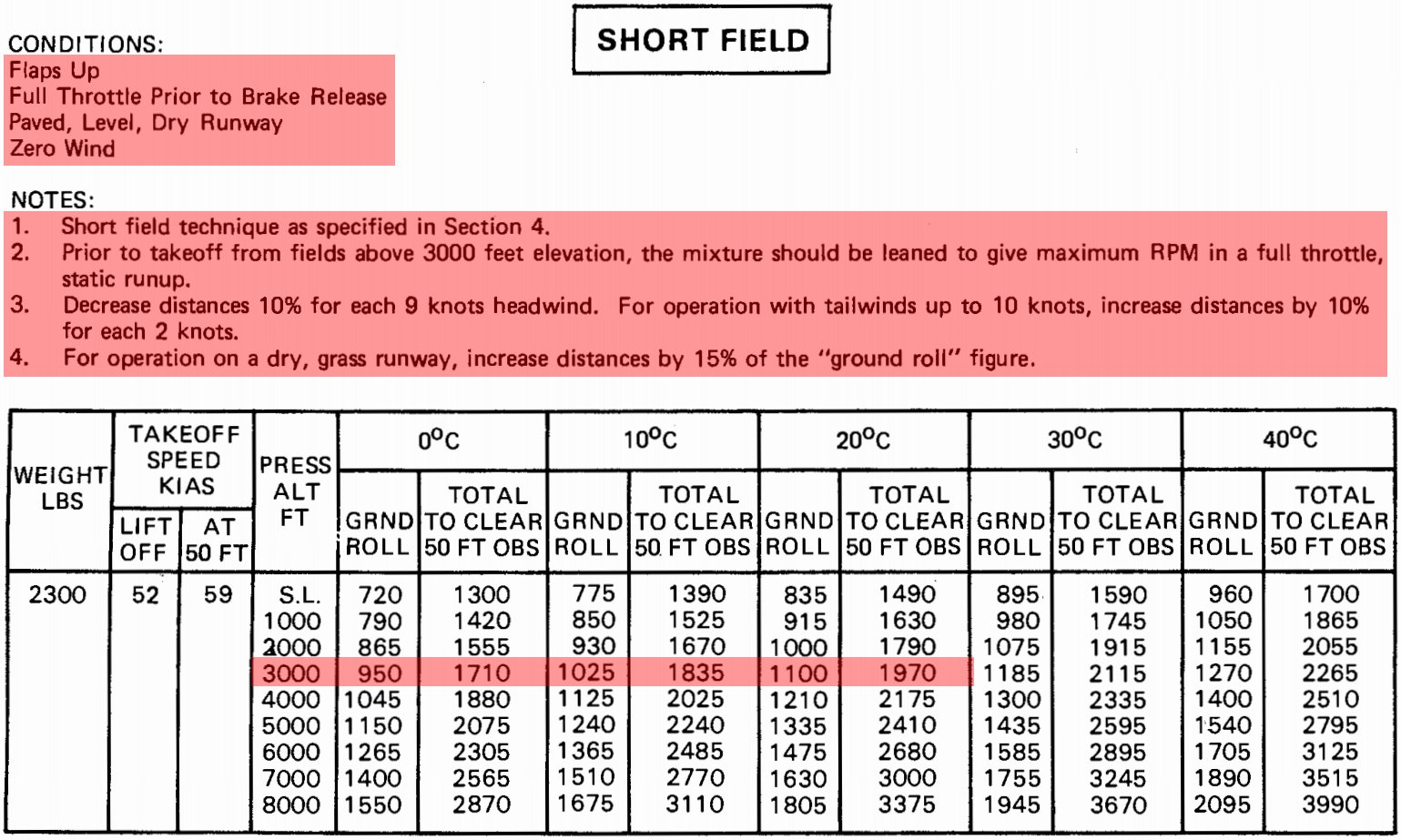
- Takeoff distance is calculated using performance charts, which can be found in your Pilot Operating Handbook/Airplane Flying Manual
- Once calculated, cross-check the required takeoff distance against runways available to see what is or is not acceptable
-
-
- As gross weight increases, the difference between nose-wheel lift-off and takeoff speed decreases
- When an instructor is not in the plane, the pitch attitude may differ
- The aircraft will be airborne sooner, climb more rapidly, and have higher performance
-
- The farther forward the CG, the longer the takeoff roll
- More authority is required to lift a heavy nose
- This can be amplified with heavy takeoff weight
- As CG moves forward, the difference between nose-wheel lift-off and takeoff speed decreases
-
- If the nose-wheel is improperly serviced:
- If the oil level is high, the springboard effect is reduced, but the change in shock absorber effect is minimal (strut compression on landing)
- If the oil level is low, the reverse is true; springboard effect is essentially normal, but shock absorption is poor
-
- Applying power to quickly may yaw the aircraft to the left due to torque, most apparent in high-powered engines
-
- The Pilot Operating Handbook/Airplane Flight Manual will specify different configurations and procedures with which to fly
-
- Flaps are considered high-lift devices
- The use of flaps allows for the aircraft to create more lift on takeoff, allowing quicker rotation into the ground effect, and reducing takeoff distance
- Aircraft must accelerate sufficiently in ground effect, however, before continuing a climb
- When lowering flaps, you are changing the chord line, which increases the angle of attack (AoA)
- This increase in AoA causes the aircraft's wing to suddenly create more lift, and therefore the aircraft will "balloon"
- When lowering flaps, anticipate this balloon effect by being ready to lower the nose
-
- Temperature is a key variable in determining density altitude
- As temperature rises, so does density altitude
- Conversely, density altitude drops with temperature
-
- The field elevation is irrelevant besides the fact that it correlates to starting at a higher density altitude
- While density altitude can actually be lower than field elevation, an aircraft on that same day at a lower altitude would almost definitely experience a lower density altitude as well, barring any environmental phenomena
- Consider planning to the 70/50 rule for takeoff, whereby if you haven't achieved 70% of your rotation speed by 50% of the runway, you should abort
-
- The winds impact how air flows over the wing of an aircraft
- Headwinds work with the motion of the aircraft to increase flow, while tailwinds push against the normal flow of air
- As a result, with a headwind, the airplane already feels some airflow over the wings before it starts to roll, thereby generating lift faster and decreasing the takeoff roll
- With a tailwind you would have increased speed to develop minimum lift, causing stress on tire, and increased takeoff distance
- Tailwind impacts are often far more detrimental than many realize
- They the increase runway distance required for takeoff
- They also may decrease directional stability, particularly before control surfaces have the authority to counteract
- Once an aircraft is airborne, the effect of winds change as the aircraft is moving relative to the airmass, not the ground
-
- Airports are not perfectly flat, and they will have some variance in altitude from one end to another, especially at large airfields
- Much like when driving a car, moving an airplane uphill requires the engine to work harder to accelerate, which results in a longer time to reach rotation speeds, increasing takeoff roll
- Conversely, taking off downhill allows for faster acceleration, resulting in a shorter takeoff roll
- When available, runway slope data will be provided. Runway slope will be shown only when it is 0.3 percent or greater. On runways less than 8000 feet, the direction of the slope up will be indicated, e.g., 0.3% up NW. On runways 8000 feet or greater, the slope will be shown (up or down) on the runway end line, e.g., RWY 13: 0.3% up., RWY 31: Pole. Rgt tfc. 0.4% down
- Aircraft slope can be determined by referencing the airport diagram found in the Chart Supplement U.S. or online at FAA.gov, or commercial sources
-
- Wind shear is a change in wind speed and/or direction over a short distance
- It can occur either horizontally or vertically and is most often associated with strong temperature inversions or density gradients
- Four common sources of low-level wind shear are:
- Frontal activity
- Thunderstorms
- Temperature inversions
- Surface obstructions
- Read more here
- If available, utilize information from Low-Level Wind Shear and Microburst Detection Systems
-
- Pavement, grass, gravel, water, snow, ice, rubber slicks
- Consider increasing margins for aborting takeoff to avoid losing control during an abort
-
- Snow, ice, and slushy conditions create a hazardous runway environment
- Consider utilizing soft field takeoff and landing procedures, minimizing opportunities to kick up hazards or lose control
-
-
- Dynamic hydroplaning occurs when standing water on a wet runway is not displaced from under the tires fast enough to allow the tire to make pavement contact over its total footprint area
- The tire rides on a wedge of water under part of the tire surface
- It can be partial or total hydroplaning, meaning the tire is no longer in contact with the runway surface area
- It is possible that as the tire breaks contact with the runway the center of pressure in the tire footprint area could move forward
- At this point, total spin-down could occur, and the wheel stops rotating, which results in total loss of braking action
- The speed at which this happens is called minimum total hydroplaning speed
-
- Viscous hydroplaning can cause complete loss of braking action at a lower speed if the wet runway is contaminated with a film of oil, dust, grease, rubber, or the runway is smooth
- The contamination combines with the water and creates a more viscous (slippery) mixture
- It should be noted that viscous hydroplaning can occur with a water depth less than dynamic hydroplaning, and skidding can occur at lower speeds, like taxiing during light rain, applying the brakes, and rolling over an oil spill
- With regards to rubber, consider that rubber is found primarily on the approach and departure end of the runway
-
- Rubber reversion hydroplaning is less known and is caused by the friction-generated heat that produces superheated steam at high pressure in the tire footprint area
- The high temperature causes the rubber to revert to its uncured state and form a seal around the tire area that traps the high-pressure steam
- It is theorized that this condition would occur on damp runways or when touchdown occurs on an isolated damp spot of a dry runway, which results in no spin-up of the tires and a reverted rubber skid
-
- Braking effectiveness is a factor of tire pressure
- Pressure also impacts the speed at which hydroplaning can occur
- Fly per the aircraft's Pilot Operating Handbook
-
- Consider how much distance is required to stop the aircraft from rotation speed
- Based on stopping distance, pick a point on the runway as an abort point
- Make the abort point part of takeoff checks to ensure it is not reached before obtaining the desired performance
- Climb Planning is necessary for several reasons, which include flight planning and obstacle clearance
- Takeoffs are optional, but landings are mandatory
- Make decisions early as to whether or not a takeoff under existing conditions is wise
- Landing distances per the book are performed under test conditions, and therefore, applying a margin of safety (perhaps 1.5 determined value) is recommended
- Pay attention to winds before takeoff - save tailwinds for cruise
- Pilots must be familiar with their aircraft's performance per Federal Aviation Regulations
- Check out the AOPA's density altitude quiz
- Review your seaplane safety knowledge by taking the Air Safety Institute's "Invasive Species" quiz
- Still looking for something? Continue searching: