Traffic Pattern Operations
Traffic pattern operations are standardized procedures that allow pilots to arrive and depart an airfield simultaneously with others.
Introduction to Traffic Pattern Operations
- Traffic Pattern procedures develop the ability to stay safely and efficiently arrive at an uncontrolled airport, or after arrival, utilize the traffic pattern
- The traffic pattern is comprised of several components which standardized flow of aircraft, at a specific altitude within the terminal area
- This standard flow allows for predictability in an otherwise extremely dangerous environment
- The traffic pattern is the ultimate goal which began with the rectangular course with many hazards
Traffic Pattern Operations Key Highlights
- Traffic pattern operations standardize aircraft flow around an airport to improve safety, predictability, and collision avoidance.
- Standard traffic pattern legs include upwind, crosswind, downwind, base, and final approach.
- Most airports use left traffic patterns unless otherwise indicated by chart supplements, signage, or air traffic control.
- Pilots should maintain appropriate traffic pattern altitude, airspeed, and spacing to support safe sequencing and aircraft control.
- Effective radio communication and visual scanning are essential for maintaining situational awareness in the traffic pattern.
- Pattern entry procedures vary depending on airport type, runway in use, weather conditions, and traffic volume.
- Wake turbulence, wind conditions, and runway configuration can affect spacing and aircraft performance in the pattern.
- Unstabilized approaches, excessive spacing compression, and poor situational awareness increase collision and runway incursion risks.
- Pilots should comply with published airport procedures, noise abatement guidance, and air traffic control instructions when applicable.
- Understanding traffic pattern operations improves airport coordination, approach stability, and overall flight safety.
Traffic Pattern Components
- The traffic pattern is divided into legs which form a rectangle
- Legs define a phase of flight associated with takeoff, landing, or closed pattern touch and go operations
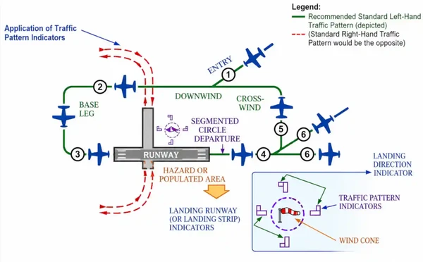
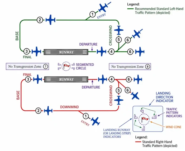
- The following terminology for the various components of a traffic pattern has been adopted as standard for use by control towers and pilots [/]
- Diagrams are intended only to illustrate terminology used in identifying various components of a traffic pattern. It should not be used as a reference or guide on how to enter a traffic pattern
-
Arrival:
- Pilots are encouraged to use the standard traffic pattern. However, those pilots who choose to execute a straight-in approach, maneuvering for and execution of the approach should not disrupt the flow of arriving and departing traffic. Likewise, pilots operating in the traffic pattern should be alert at all times for aircraft executing straight-in approaches
- *RP indicates special conditions exist and refers pilots to the Chart Supplement U.S
- Right traffic patterns are not shown at airports with full-time control towers
- Pilots are encouraged to use the standard traffic pattern. However, those pilots who choose to execute a straight-in approach, maneuvering for and execution of the approach should not disrupt the flow of arriving and departing traffic. Likewise, pilots operating in the traffic pattern should be alert at all times for aircraft executing straight-in approaches
-
Upwind Leg:
- A flight path parallel to the landing runway in the landing direction
- Note, the upwind leg is separate and distinct from the departure leg and often used to reference the flight path flown after takeoff (or a touch and go)
- Still, expect many will still use two used interchangeably
-
Crosswind Leg:
- A flight path at right angles to the landing runway off its takeoff end
- The direction of the crosswind leg (left or right turn) is dictated by the airport publications or tower
- It is recommended the turn from upwind to crosswind be at 700 ft AGL (~300 ft below traffic pattern altitude), unless local procedures or ATC dicated otherwise
-
Downwind Leg:
- A flight path parallel to the landing runway in the opposite direction of landing
- While it is the longest leg, it requires the most vigilance for traffic entering and departing
-
Base Leg:
- A flight path at right angles to the landing runway off its approach end and extending from the downwind leg to the intersection of the extended runway centerline
-
Final Approach:
- A flight path in the direction of landing along the extended runway centerline from the base leg to the runway
- Before touching down, check for waive-off lights if present, or light signals from tower
-
Departure:
- The flight path which begins after takeoff and continues straight ahead along the extended runway centerline
- The departure climb continues until reaching a point at least 1/2 mile beyond the departure end of the runway and within 300 feet of the traffic pattern altitude
- May exit 45° off in the direction of the pattern turns as well
Traffic Pattern Altitude
- Traffic pattern altitudes should be maintained unless another traffic pattern altitude is published in the Chart Supplement U.S. or unless otherwise required
- Propeller-driven aircraft enter the traffic pattern at 1,000 feet above ground level (AGL)
- Large and turbine-powered aircraft enter the traffic pattern at an altitude of not less than 1,500 feet AGL or 500 feet above the established pattern altitude
- Helicopters operating in the traffic pattern may fly a pattern similar to the fixed-wing aircraft pattern, but at a lower altitude (500 AGL) and closer to the runway. This pattern may be on the opposite side of the runway from fixed-wing traffic when airspeed requires or for practice power-off landings (autorotation) and if local policy permits. Landings not to the runway must avoid the flow of fixed wing traffic
- A pilot may vary the size of the traffic pattern depending on the aircraft's performance characteristics. Pilots of en route aircraft should be constantly alert for aircraft in traffic patterns and avoid these areas whenever possible
- Except when conducting a circling approach or unless otherwise required by ATC, each pilot must:
- Circle the airport to the left if operating an airplane; or
- Avoid the flow of fixed-wing aircraft, if operating a helicopter
- On Sectional, Aeronautical, and VFR Terminal Area Charts, right traffic patterns are indicated at public-use and joint-use airports with the abbreviation "RP" (for Right Pattern), followed by the appropriate runway number(s) at the bottom of the airport data block
- EXAMPLE: RP 9, 18, 22R
- RP* indicates special conditions exist and refers pilots to the Chart Supplement U.S.
- Right traffic patterns are not shown at airports with full-time control towers
- EXAMPLE: RP 9, 18, 22R
- Unless otherwise required by the applicable distance from clouds (FAR 91.155) or operations, pilots should maintain traffic pattern altitude
- Traffic patterns are left turns by standard, unless ATC or the Chart Supplement U.S. states otherwise, as shown in Meadows Field below, under RWY 30R and 12R with the text "Rgt tfc"
- Wind conditions affect all airplanes in varying degrees. Figure 4-3-4 is an example of a chart used to determine the headwind, crosswind, and tailwind components based on wind direction and velocity relative to the runway. Pilots should refer to similar information provided by the aircraft manufacturer when determining these wind components
Keys to Traffic Pattern Operations
- Enter pattern in level flight, abeam midpoint of the runway, at pattern altitude (1,000' AGL is recommended pattern altitude unless established otherwise...)
- Try not to enter the pattern on base/final even if that is the quickest as it does not afford you a look at the runway until you're on final
- Maintain pattern altitude until abeam approach end of the landing runway on downwind leg
- Complete turn to final at least 1/4 mile from the runway
- Continue straight ahead until beyond departure end of runway
- If remaining in the traffic pattern, commence turn to crosswind leg beyond the departure end of the runway within 300' of pattern altitude
- If departing the traffic pattern, continue straight out, or exit with a 45° turn (to the left when in a left-hand traffic pattern; to the right when in a right-hand traffic pattern) beyond the departure end of the runway, after reaching pattern altitude
- Maintain situational awareness to anyone entering the traffic pattern on a 45° angle as they may be flying directly toward or paralleling the departure track
- Do not overshoot final or continue on a track, which will penetrate the final approach of the parallel runway
- Do not continue on a track, which will penetrate the departure path of a parallel runway
- Maintain approximately 1/2 a mile distance from the runway when on downwind
- Maintaining this predictable track makes traffic predictable and positions aircraft in the best position to quickly land in the event of an emergency
- Distance from the airport can be referenced by landmarks or using runway lengths for perspective
Towered Airports
- When operating at an airport where traffic control is exercised by a tower, two-way communication is required, unless otherwise authorized
- Initial callup should be made about 15 miles from the airport
- Unless there is a good reason to leave the tower frequency before exiting the Class B, Class C, and Class D surface areas, it is a good operating practice to remain on the tower frequency for the purpose of receiving traffic information
- It is not necessary to request permission to leave the tower frequency once outside of Class B, Class C, and Class D surface areas, as it reduces frequency congestion
- When operating at uncontrolled fields, keep to normal towered procedures to remain predictable
- Not all airports with an operating control tower will have Class D airspace and thus do not have weather reporting which is a requirement for surface based controlled airspace, previously known as a control zone
- The controlled airspace over these airports will normally begin at 700' or 1,200' AGL (see Class Echo Airspace) and can be determined from the visual aeronautical charts
- Pilots are expected to use good operating practices and communicate with the control tower, same as above
- When necessary, the tower controller will issue clearances or other information for aircraft to generally follow the desired flight path (traffic patterns) when flying in Class B, Class C, and Class D surface areas and the proper taxi routes when operating on the ground
- Thus, if not otherwise authorized or directed by the tower, pilots of fixed-wing aircraft approaching to land must circle the airport to the left
- Pilots approaching to land in a helicopter must avoid the flow of fixed-wing traffic
- In all instances, an appropriate clearance must be received from the tower before landing
- Many towers will have radar display which are intended to enhance the effectiveness and efficiency of the local control, or tower, position
- They are not intended to provide radar services or benefits to pilots except as they may accrue through a more efficient tower operation
- The four basic uses are:
-
Determining an Aircraft's Exact Location:
- Accomplished by radar identifying the VFR aircraft through any of the techniques available to a radar position, such as having the aircraft squawk ident.
- Once identified, the aircraft's position and spatial relationship to other aircraft can be quickly determined, and standard instructions regarding VFR operation in Class B, Class C, and Class D surface areas will be issued
- Once initial radar identification of a VFR aircraft has been established and the appropriate instructions have been issued, radar monitoring may be discontinued; the reason being that the local controller's primary means of surveillance in VFR conditions is visually scanning the airport and local area
-
Provide Radar Traffic Advisories:
- Radar traffic advisories may be provided to the extent that the local controller is able to monitor the radar display
- Local control has primary control responsibilities to the aircraft operating on the runways, which will normally supersede radar monitoring duties
-
Provide Direction or Suggested Heading:
- The local controller may provide pilots flying VFR with generalized instructions which will facilitate operations; e.g., "Proceed southwest-bound, enter a right downwind runway three zero," or provide a suggested heading to establish radar identification or as an advisory aid to navigation; "Suggested heading two two zero, for radar identification"
- In both cases, the instructions are advisory aids to the pilot flying VFR and are not radar vectors which gives pilots complete discretion regarding acceptance of the suggestions as they have sole responsibility for seeing and avoiding other aircraft
-
Provide Information and Instructions:
- In an example of this situation, the local controller would use the radar to advise a pilot on an extended downwind when to turn base leg
-
- NOTE: The above tower radar applications are intended to augment the standard functions of the local control position. There is no controller requirement to maintain constant radar identification. In fact, such a requirement could compromise the local controller's ability to visually scan the airport and local area to meet FAA responsibilities to the aircraft operating on the runways and within the Class B, Class C, and Class D surface areas. Normally, pilots will not be advised of being in radar contact since that continued status cannot be guaranteed and since the purpose of the radar identification is not to establish a link for the provision of radar services
- A few of the radar equipped towers are authorized to use the radar to ensure separation between aircraft in specific situations, while still others may function as limited radar approach controls
- The various radar uses are strictly a function of FAA operational need. The facilities may be indistinguishable to pilots since they are all referred to as tower and no publication lists the degree of radar use
- Therefore, when in communication with a tower controller who may have radar available, do not assume that constant radar monitoring and complete ATC radar services are being provided
Airport Operations Without Operating Control Tower
- There is no substitute for alertness while in the vicinity of an airport. It is essential that pilots be alert and look for other traffic and exchange traffic information when approaching or departing an airport without an operating control tower. This is of particular importance since other aircraft may not have communication capability or, in some cases, pilots may not communicate their presence or intentions when operating into or out of such airports. To achieve the greatest degree of safety, it is essential that:
- All radio-equipped aircraft transmit/receive on a common frequency identified for the purpose of airport advisories; and
- Pilots use the correct airport name, as identified in appropriate aeronautical publications, to reduce the risk of confusion when communicating their position, intentions, and/or exchanging traffic information
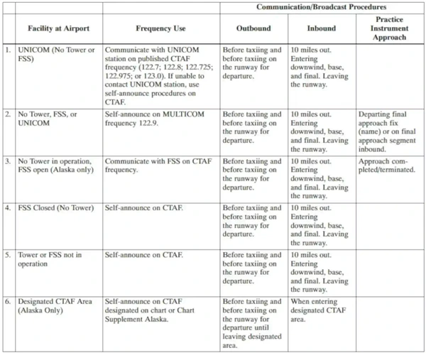
- An airport may have a full or part-time tower or FSS located on the airport, a full or part-time UNICOM station or no aeronautical station at all. There are three ways for pilots to communicate their intention and obtain airport/traffic information when operating at an airport that does not have an operating tower:
- By communicating with an FSS; (FSS airport advisories are available only in Alaska
- A UNICOM operator, or; []
- By making a self-announce broadcast
- Many airports are now providing completely automated weather, radio check capability and airport advisory information on an automated UNICOM system. These systems offer a variety of features, typically selectable by microphone clicks, on the UNICOM frequency. Availability of the automated UNICOM will be published in the Chart Supplement U.S. and approach charts
-
Airport Advisory/Information Services Provided by a FSS:
- There are three advisory type services provided at selected airports
- Local Airport Advisory (LAA) is available only in Alaska and provided at airports that have a FSS physically located on the airport, which does not have a control tower or where the tower is operated on a - basis. The CTAF for LAA airports is disseminated in the appropriate aeronautical publications
- Remote Airport Information Service (RAIS) is provided in support of special events at nontowered airports by request from the airport authority
- In communicating with a CTAF FSS, check the airport's automated weather and establish two-way communications before transmitting outbound/inbound intentions or information. An inbound aircraft should initiate contact approximately 10 miles from the airport, reporting aircraft identification and type, altitude, location relative to the airport, intentions (landing or over flight), possession of the automated weather, and request airport advisory or airport information service. A departing aircraft should initiate contact before taxiing, reporting aircraft identification and type, VFR or IFR, location on the airport, intentions, direction of take-off, possession of the automated weather, and request airport advisory or information service. Also, report intentions before taxiing onto the active runway for departure. If you must change frequencies for other service after initial report to FSS, return to FSS frequency for traffic update
- Inbound:
- Vero Beach radio, Centurion Six Niner Delta Delta is ten miles south, two thousand, landing Vero Beach. I have the automated weather, request airport advisory
- Outbound:
- Vero Beach radio, Centurion Six Niner Delta Delta, ready to taxi to runway 22, VFR, departing to the southwest. I have the automated weather, request airport advisory
- Inbound:
- Airport advisory service includes wind direction and velocity, favored or designated runway, altimeter setting, known airborne and ground traffic, NOTAMs, airport taxi routes, airport traffic pattern information, and instrument approach procedures. These elements are varied so as to best serve the current traffic situation. Some airport managers have specified that under certain wind or other conditions designated runways be used. Pilots should advise the FSS of the runway they intend to use
- All aircraft in the vicinity of an airport may not be in communication with the FSS
- There are three advisory type services provided at selected airports
-
Information Provided by Aeronautical Advisory Stations (UNICOM):
- UNICOM is a non-government air/ground radio communication station which may provide airport information at public use airports where there is no tower or FSS
- On pilot request, UNICOM stations may provide pilots with weather information, wind direction, the recommended runway, or other necessary information
- If the UNICOM frequency is designated as the CTAF, it will be identified in appropriate aeronautical publications []
-
UNICOM Communications Procedures
- In communicating with a UNICOM station, the following practices will help reduce frequency congestion, facilitate a better understanding of pilot intentions, help identify the location of aircraft in the traffic pattern, and enhance safety of flight:
- Select the correct UNICOM frequency
- State the identification of the UNICOM station you are calling in each transmission
- Speak slowly and distinctly
- Report approximately 10 miles from the airport, reporting altitude, and state your aircraft type, aircraft identification, location relative to the airport, state whether landing or overflight, and request wind information and runway in use
- Report on downwind, base, and final approach
- Report leaving the runway
- Recommended UNICOM phraseologies:
- Inbound:
- FREDERICK UNICOM CESSNA EIGHT ZERO ONE TANGO FOXTROT 10 MILES SOUTHEAST DESCENDING THROUGH (altitude) LANDING FREDERICK, REQUEST WIND AND RUNWAY INFORMATION FREDERICK
- FREDERICK TRAFFIC CESSNA EIGHT ZERO ONE TANGO FOXTROT ENTERING DOWNWIND/BASE/ FINAL (as appropriate) FOR RUNWAY ONE NINER (full stop/touch-and-go) FREDERICK
- FREDERICK TRAFFIC CESSNA EIGHT ZERO ONE TANGO FOXTROT CLEAR OF RUNWAY ONE NINER FREDERICK
- Outbound:
- FREDERICK UNICOM CESSNA EIGHT ZERO ONE TANGO FOXTROT (location on airport) TAXIING TO RUNWAY ONE NINER, REQUEST WIND AND TRAFFIC INFORMATION FREDERICK
- FREDERICK TRAFFIC CESSNA EIGHT ZERO ONE TANGO FOXTROT DEPARTING RUNWAY ONE NINER. "REMAINING IN THE PATTERN" OR "DEPARTING THE PATTERN TO THE (direction) (as appropriate)" FREDERICK
- Inbound:
- In communicating with a UNICOM station, the following practices will help reduce frequency congestion, facilitate a better understanding of pilot intentions, help identify the location of aircraft in the traffic pattern, and enhance safety of flight:
-
Self-Announce Position and/or Intentions:
- Self-announce is a procedure whereby pilots broadcast their position or intended flight activity or ground operation on the designated CTAF. This procedure is used primarily at airports which do not have an FSS on the airport. The self-announce procedure should also be used if a pilot is unable to communicate with the FSS on the designated CTAF. Pilots stating, "Traffic in the area, please advise" is not a recognized Self-Announce Position and/or Intention phrase and should not be used under any condition
- If an airport has a tower and it is temporarily closed, or operated on a part-time basis and there is no FSS on the airport or the FSS is closed, use the CTAF to self-announce your position or intentions
- Where there is no tower, FSS, or UNICOM station on the airport, use MULTICOM frequency 122.9 for self-announce procedures. Such airports will be identified in appropriate aeronautical information publications
-
Straight-in Landings:
- The FAA discourages VFR straight-in approaches to landings due to the increased risk of a mid-air collision. However, if a pilot chooses to execute a straight-in approach for landing without entering the airport traffic pattern, the pilot should self-announce their position on the designated CTAF approximately 8 to 10 miles from the airport and coordinate their straight-in approach and landing with other airport traffic. Pilots executing a straight-in approach (IFR or VFR) do not have priority over other aircraft in the traffic pattern, and must comply with the provisions of 14 CFR 91.113 (g), Right-of-way rules
-
Traffic Pattern Operations:
- All traffic within a 10-mile radius of a non-towered airport or a part-time-towered airport when the control tower is not operating, should monitor and communicate on the designated CTAF when entering the traffic pattern. Pilots operating in the traffic pattern or on a straight-in approach must be alert at all times to other aircraft in the pattern, or conducting straight-in approaches, and communicate their position to avoid a possible traffic conflict. In the airport traffic pattern and while on straight-in approaches to a runway, effective communication and a pilot's responsibility to see-and-avoid are essential mitigations to avoid a possible midair collision. In addition, following established traffic pattern procedures eliminates excessive maneuvering at low altitudes, reducing the risk of loss of aircraft control
- Reference FAA Advisory Circular (AC) 90-66, Non-Towered Airport Flight Operations
-
Practice Approaches:
- Pilots conducting practice instrument approaches should be particularly alert for other aircraft that may be departing in the opposite direction
- When conducting any practice approach, regardless of its direction relative to other airport operations, pilots should make announcements on the CTAF as follows:
- Departing the final approach fix, inbound (nonprecision approach) or departing the outer marker or fix used in lieu of the outer marker, inbound (precision approach);
- Established on the final approach segment or immediately upon being released by ATC;
- Upon completion or termination of the approach; and
- Upon executing the missed approach procedure
- Departing aircraft should always be alert for arrival aircraft coming from the opposite direction
- Recommended self-announce phraseologies: It should be noted that aircraft operating to or from another nearby airport may be making self-announce broadcasts on the same UNICOM or MULTICOM frequency. To help identify one airport from another, the airport name should be spoken at the beginning and end of each self-announce transmission. When referring to a specific runway, pilots should use the runway number and not use the phrase "Active Runway"
- Inbound:
- "Strawn traffic, Apache Two Two Five Zulu, [position], [altitude], [descending] or entering downwind/base/final (as appropriate) runway one seven full stop, touch-and-go, Strawn"
- "Strawn traffic, Apache Two Two Five Zulu clear of runway one seven Strawn"
- Outbound:
- "Strawn traffic, Queen Air Seven One Five Five Bravo [location on airport] taxiing to runway two six Strawn"
- "Strawn traffic, Queen Air Seven One Five Five Bravo departing runway two six. Departing the pattern to the [direction], climbing to [altitude] Strawn"
- Practice Instrument Approach:
- Strawn traffic, Cessna Two One Four Three Quebec (position from airport) inbound descending through (altitude) practice (name of approach) approach runway three five Strawn
- Strawn traffic, Cessna Two One Four Three Quebec practice (type) approach completed or terminated runway three five Strawn
- Inbound:
-
Communicating on a Common Frequency:
- The key to communicating at an airport without an operating control tower is selection of the correct common traffic advisory frequency, or CTAF. A CTAF is a frequency designated for the purpose of carrying out airport advisory practices while operating to or from an airport without an operating control tower. The CTAF may be a UNICOM, MULTICOM, FSS, or tower frequency and is identified in appropriate aeronautical publications
- FSS frequencies are available only in Alaska
- In Alaska, a CTAF may also be designated for the purpose of carrying out advisory practices while operating in designated areas with a high volume of VFR traffic
- The CTAF frequency for a particular airport or area is contained in the Chart Supplement U.S., Alaska Supplement, Alaska Terminal Publication, Instrument Approach Procedure Charts, and Instrument Departure Procedure (DP) Charts
- Also, the CTAF frequency can be obtained by contacting any FSS
- Use of the appropriate CTAF, combined with a visual alertness and application of the following recommended good operating practices, will enhance safety of flight into and out of all uncontrolled airports
- The key to communicating at an airport without an operating control tower is selection of the correct common traffic advisory frequency, or CTAF. A CTAF is a frequency designated for the purpose of carrying out airport advisory practices while operating to or from an airport without an operating control tower. The CTAF may be a UNICOM, MULTICOM, FSS, or tower frequency and is identified in appropriate aeronautical publications
-
Recommended Traffic Advisory Practices:
- Pilots of inbound traffic should monitor and communicate as appropriate on the designated CTAF from 10 miles to landing. Pilots of departing aircraft should monitor/communicate on the appropriate frequency from start-up, during taxi, and until 10 miles from the airport unless the CFRs or local procedures require otherwise. []
- Pilots of aircraft conducting other than arriving or departing operations at altitudes normally used by arriving and departing aircraft should monitor/communicate on the appropriate frequency while within 10 miles of the airport unless required to do otherwise by the CFRs or local procedures. Such operations include parachute jumping/dropping, en route, practicing maneuvers, etc.
- In Alaska, pilots of aircraft conducting other than arriving or departing operations in designated CTAF areas should monitor/communicate on the appropriate frequency while within the designated area, unless required to do otherwise by CFRs or local procedures. Such operations include parachute jumping/dropping, en route, practicing maneuvers, etc.


Traffic Pattern Arrival
- Procedure:
- Complete the descent checklist
- At least 10 NM from the airport, attempt to determine the active runway
- If the runway in use cannot be determined:
- Over fly the airport at 500-1,000' above traffic pattern altitude to observe traffic, wind direction indications, etc. to determine a runway to use
- At least 2 NM from the runway, enter the traffic pattern at traffic pattern altitude on a 45° entry to the downwind, maintaining a none-half mile distance from the runway on the downwind leg
- Complete the appropriate approach and landing procedure
- Maintain pattern altitude until abeam approach end of the landing runway on the downwind leg
- Complete turn to final at least 1/4 mile from the runway
Traffic Pattern Responsibilities
-
Pilot Responsibilities:
- Acknowledges receipt of traffic advisories
- Informs controller if traffic in sight
- Advises ATC if a vector to avoid traffic is desired
- Does not expect to receive radar traffic advisories on all traffic. Some aircraft may not appear on the radar display. Be aware that the controller may be occupied with higher priority duties and unable to issue traffic information for a variety of reasons
- Advises controller if service is not desired
-
Controller Responsibilities:
- Issues radar traffic to the maximum extent consistent with higher priority duties except in Class A airspace
- Provides vectors to assist aircraft to avoid observed traffic when requested by the pilot
- Issues traffic information to aircraft in the Class B, C, and D surface areas for sequencing purposes
- Controllers are required to issue to each aircraft operating on intersecting or non-intersecting converging runways where projected flight paths will cross
Visual Indicators at Airports Without an Operating Control Tower
- At those airports without an operating control tower, a segmented circle visual indicator system, if installed, (see AIM, Paragraph 4-1-9, Traffic Advisory Practices at Airports Without Operating Control Towers) is designed to provide traffic pattern information
- The segmented circle system consists of the following components:
-
Segmented Circle:
- Located in a position affording maximum visibility to pilots in the air and on the ground and providing a centralized location for other elements of the system []
-
Wind Direction Indicators:
- A wind cone, wind sock, or wind tee installed near the operational runway to indicate wind direction. The large end of the wind cone/wind sock points into the wind as does the large end (cross bar) of the wind tee. In lieu of a tetrahedron and where a wind sock or wind cone is collocated with a wind tee, the wind tee may be manually aligned with the runway in use to indicate landing direction. These signaling devices may be located in the center of the segmented circle and may be lighted for night use. Pilots are cautioned against using a tetrahedron to indicate wind direction []
- In the case of conflicting wind socks, consider their placement, obstacles that may cause interference, and which may have proximity to the runway
-
Landing Direction Indicator:
- A tetrahedron is installed when conditions at the airport warrant its use. It may be used to indicate the direction of landings and takeoffs. A tetrahedron may be located at the center of a segmented circle and may be lighted for night operations. The small end of the tetrahedron points in the direction of landing. Pilots are cautioned against using a tetrahedron for any purpose other than as an indicator of landing direction. Further, pilots should use extreme caution when making runway selection by use of a tetrahedron in very light or calm wind conditions as the tetrahedron may not be aligned with the designated calm-wind runway. At airports with control towers, the tetrahedron should only be referenced when the control tower is not in operation. Tower instructions supersede tetrahedron indications
-
Landing Strip Indicators:
- Installed in pairs as shown in the segmented circle diagram and used to show the alignment of landing strips
-
Traffic Pattern Indicators:
- Arranged in pairs in conjunction with landing strip indicators and used to indicate the direction of turns when there is a variation from the normal left traffic pattern. (If there is no segmented circle installed at the airport, traffic pattern indicators may be installed on or near the end of the runway)
-
- Preparatory to landing at an airport without a control tower, or when the control tower is not in operation, pilots should concern themselves with the indicator for the approach end of the runway to be used. When approaching for landing, all turns must be made to the left unless a traffic pattern indicator indicates that turns should be made to the right. If the pilot will mentally enlarge the indicator for the runway to be used, the base and final approach legs of the traffic pattern to be flown immediately become apparent. Similar treatment of the indicator at the departure end of the runway will clearly indicate the direction of turn after takeoff
- When two or more aircraft are approaching an airport for the purpose of landing, the pilot of the aircraft at the lower altitude has the right-of-way over the pilot of the aircraft at the higher altitude. However, the pilot operating at the lower altitude should not take advantage of another aircraft, which is on final approach to land, by cutting in front of, or overtaking that aircraft


Unexpected Maneuvers in the Airport Traffic Pattern
- There have been several incidents in the vicinity of controlled airports that were caused primarily by aircraft executing unexpected maneuvers
- Controllers establish the sequence of arriving and departing aircraft by requiring them to adjust flight as necessary to achieve proper spacing
- These adjustments can only be based on observed traffic, accurate pilot reports, and anticipated aircraft maneuvers
- Pilots are expected to cooperate so as to preclude disrupting traffic flows or creating conflicting patterns
- The pilot-in-command of an aircraft is directly responsible for and is the final authority as to the operation of the aircraft
- On occasion it may be necessary for pilots to maneuver their aircraft to maintain spacing with the traffic they have been sequenced to follow
- The controller can anticipate minor maneuvering such as shallow "S" turns
- The controller cannot, however, anticipate a major maneuver such as a 360° turn
- If a pilot makes a 360° turn after obtaining a landing sequence, the result is usually a gap in the landing interval and, more importantly, it causes a chain reaction which may result in a conflict with following traffic and an interruption of the sequence established by the tower or approach controller
- Should a pilot decide to make maneuvering turns to maintain spacing behind a preceding aircraft, the pilot should always advise the controller if at all possible
- Except when requested by the controller or in emergency situations, a 360° turn should never be executed in the traffic pattern or when receiving radar service without first advising the controller
Traffic Pattern Operations Knowledge Check


Traffic Pattern Operations Conclusion
- The name says it all as the "pattern" is a predictable flow of traffic in a congested area
- Remember that it is not required to have a radio (and therefore make radio calls) prior to takeoff or landing at an uncontrolled airfield
- Always observe right-of-way rules
- Instances where an aircraft fails to (or even attempts) to takeoff and land on the wrong runway or taxiway generates a "wrong surface event" reporting
- Additional resources are available through tools such as the FAA's Runway Safety Simulator.
- Remember back to basics in the rectangular course when it comes to winds
- Tailwinds, and headwinds will effect an aircraft differently depending on the pattern direction and the specific leg of the pattern, lending to over and undershoots
- Traffic pattern not regulatory, making the PIC, not tower, responsible for cloud separation in pattern
- Historical wind information (wind roses) can be found at Windhistory.com.
- When crossing over the traffic pattern, account for piston traffic at 1000' AGL and also turbine aircraft at 1500' AGL
- Pilots should review the impacts of the impossible turn as part of traffic pattern operations
- Note that helicopters will often fly opposite patterns (left vs. right) as they are required by regulation to avoid the flow of fixed-wing traffic
- Additional resources are available through tools such as the FAA's Runway Safety Simulator.
- Still looking for something? Continue searching:
Traffic Pattern Operations References
- Air Facts Journal - Where Is The Upwind Leg?.
- Federal Aviation Administration - Pilot/Controller Glossary.
- Advisory Circular (90-66) Non-Towered Airport Flight Operations.
- Aeronautical Information Manual (3-5-4) Parachute Jump Aircraft Operations.
- Aeronautical Information Manual (4-1-8) Approach Control Service for VFR Arriving Aircraft.
- Aeronautical Information Manual (4-1-9) Traffic Advisory Practices at Airports Without Operating Control Towers.
- Aeronautical Information Manual (4-3-1) General.
- Aeronautical Information Manual (4-3-2) Airports with an Operating Control Tower.
- Aeronautical Information Manual (4-3-3) Traffic Pattern.
- Aeronautical Information Manual (4-3-5) Unexpected Maneuvers in the Airport Traffic Pattern.
- Aeronautical Information Manual (5-5-10) Traffic Advisories (Traffic Information).
- AOPA - Safety Quiz: Towered Airport Operations.
- AOPA - Operations at Airports.
- Federal Aviation Regulations (91.155) Basic VFR weather minimums.
- Pilot Workshop - Traffic Pattern Rules.