Flight Planning
Flight Planning involves various types of navigation procedures and techniques used to prepare for a flight.
Introduction to Flight Planning
- Flight planning is the process in which a pilot prepares for an upcoming flight
- While often associated with completing a navigation log for a cross-country, flight planning is a process that must be conducted even for local flights in the traffic pattern
- It is a descriptive process therefore involving more than one type of navigation.
- If no wind information is available, plan using statistical winds, make them headwinds to be conservative in your fuel planning
- Pilots will chose a route of flight and select cruise altitude based on a variety of factors
- Course: is pre-flight
- Track: is flown
- Charts are all "true" as in true north and must be compensated to find magnetic north
- Include the following:
- Diverts (direction and channels/frequencies)
- Checkpoints:
- Check points should be set approximately 10 NM apart
- Your first checkpoint should be Top of Climb (TOC) and the last should be Top of Descent (TOD)
Flight Planning Key Highlights
- Flight planning involves preparing all operational, navigational, weather, and performance information necessary for a safe flight.
- Effective flight planning includes route selection, fuel calculations, weather analysis, aircraft performance evaluation, and risk assessment.
- Pilots should review NOTAMs, airspace restrictions, airport information, and forecast weather conditions before departure.
- Weight and balance calculations help ensure the aircraft remains within approved loading and performance limitations.
- Navigation planning may include checkpoints, headings, fuel stops, alternates, and expected en route procedures.
- Weather conditions such as winds aloft, turbulence, icing, ceilings, and visibility significantly affect flight planning decisions.
- Fuel reserves and contingency planning improve operational flexibility and emergency preparedness during flight operations.
- Modern flight planning tools and Electronic Flight Bags (EFBs) improve efficiency and situational awareness during preflight preparation.
- Poor flight planning can increase operational workload, fuel risks, weather exposure, and decision-making errors.
- Understanding flight planning improves aeronautical decision-making, operational efficiency, and overall flight safety.
Flight Planning
- The purpose of flight planning is to become familiar with information pertaining to an intended flight
- The work put in is also necessary to accurately complete FAA Form 7233-1, better known as a flight plan, if one is required
-
Initial Planning Considerations:
- According to FAR 91.103, pilots in command are required to familiarize themselves with information pertaining to the flight
- The "how" is a product of flight planning but the "who, what, when, and where" provides a useful starting point
- These required actions can be remembered using the acronym "NW KRAFT" or "WX-KRAFTN"
- WX: Weather Reports.
- K: Known ATC Delays (check https://www.fly.faa.gov/adv/advAdvisoryForm.jsp.
- R: Runway Lengths of intended use
- A: Alternatives if the flight cannot be completed as planned
- F: Fuel requirements
- T: Takeoff and landing distances
- N: Notice to Airmen (NOTAMS) and Temporary Flight Restrictions (TFRs).
Fuel Planning
- Fuel planning includes:
- The SETTO, or start, taxi, and takeoff fuel.
- Fuel to climb.
- Fuel in cruise.
- Fuel in descent.
- Fuel in terminal area.
- Fuel reserve.
-
Aviation Fuel Reserve Requirements:
-
VFR Fuel Requirements:
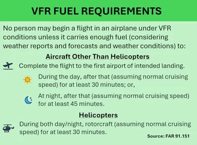
- VFR fuel requirements are governed by FAR 91.151. []
- No person may begin a flight in an airplane under VFR conditions unless it carries enough fuel (considering weather reports and forecasts and weather conditions) to:
- Complete the flight to the first airport of intended landing.
- During the day, after that (assuming normal cruising speed) for at least 30 minutes; or,.
- At night, after that (assuming normal cruising speed) for at least 45 minutes.
- No person may begin a flight in a rotorcraft under VFR conditions unless there is enough fuel (considering weather reports and forecasts and weather conditions) to fly to the first point of intended landing and, assuming normal cruising speed, to fly after that for at least 20 minutes.
-
IFR Fuel Requirements:
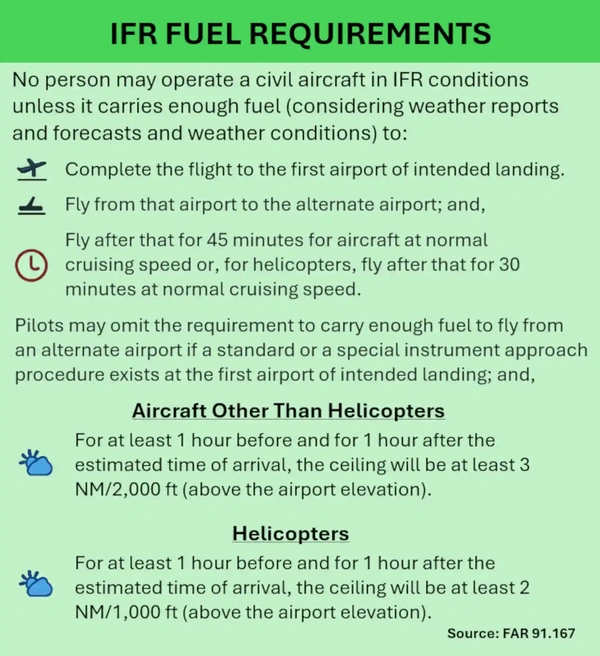
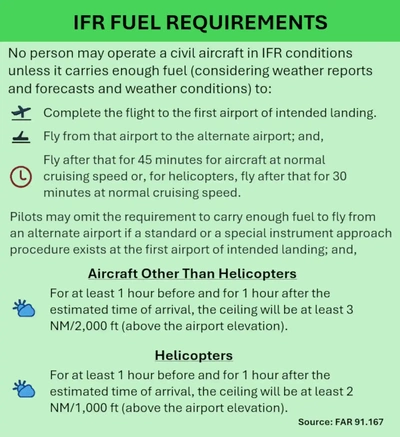
- IFR fuel requirements are governed by FAR 91.167. []
- No person may operate a civil aircraft in IFR conditions unless it carries enough fuel (considering weather reports and forecasts and weather conditions) to:
- Complete the flight to the first airport of intended landing;
- Fly from that airport to the alternate airport; and,.
- Fly after that for 45 minutes for aircraft at normal cruising speed or, for helicopters, fly after that for 30 minutes at normal cruising speed.
- Although the 45-minute rule above will never change, pilots may omit the requirement to carry enough fuel to fly from an alternate airport if:
- A standard instrument approach procedure to, or a special instrument approach procedure exists at the first airport of intended landing; and,.
- Appropriate weather reports or weather forecasts, or a combination of them, indicate the following:
-
Aircraft Other Than Helicopters:
- For at least 1 hour before and for 1 hour after the estimated time of arrival, the ceiling will be at least 3 NM/2,000 ft (2,000 feet above the airport elevation, and the visibility will be at least three statute miles).
-
Helicopters:
- At the estimated time of arrival and for 1 hour after the estimated time of arrival, the ceiling will be at least 2 NM/1,000 ft above the airport elevation, or at least 400 feet above the lowest applicable approach minima, whichever is higher, and the visibility will be at least two statute miles.
-
- Essentially, pilots may omit fuel planning for an alternate when an alternate is not required.
-
-
Performance Required:
- First, determine how much you intend to carry between passengers, cargo, and then fuel, all necessary to complete the weight and balance.
- With the aircraft weight known, atmospheric information lends to takeoff performance and route selection.

Flight Planning and Navigation Tools
- Various tools are necessary to complete a flight plan
- They include:
- Flight Computer. []
- Navigation Charts
- Plotter. []
- Internet resources
- Digital Navigation Logs
- AOPA iFlightPlanner.


Mission Considerations
- Flight planning begins with determining the mission, that is:
- What are you carrying?
- Where are you going?
- Carrying people or baggage impacts fuel and time considerations, which informs route planning and potential intermediate stops to reach the destination
- Consider weight and balance limitations (people, baggage, and fuel with reserves) - can it be done in one trip?
- Provided the aircraft meets weight and balance mission requirements, determine if it has the necessary takeoff and climb performance, as well as the necessary approach and landing performance.
- Consider personal minimums with any calculation, including margins of safety relative to chart calculated performance numbers.
Route Planning
-
Determining a Route:
-
Airspace to be Crossed:
- Review processes and procedures to cross special use, other, and various classifications of airspace.
-
Choosing Checkpoints and/or Landmarks:
- Checkpoints allow you to follow the progress of your flight against your planning calculations
- Landmarks can be checkpoints but may also inform a pilot where they are in relation to checkpoints
- Considerations for selection of either are:
- Are they unique enough to be identified?
- Are they large enough to be found?
- Are they small enough to be considered a "point?"
- Checkpoints should be appropriately 10 NM apart
- They may be points off the route which you can identify when abeam
- Use of tools such as satellite maps (Google, Bing, etc.) allow for you to preview checkpoints.
-
Types of Landmarks:
-
Positive Landmarks:
- Can be positively identified and plotted as a point on a chart (i.e., mountains, large bodies of water, etc.)
- You need not pass directly over a positive landmark for it to be useful to you
- Be cautious of man-made landmarks as they may have changed, moved, or no longer exist
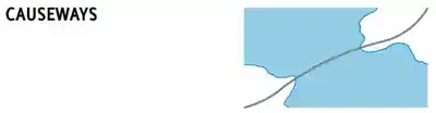
- Hydrography (water features): []
- Water features are depicted using two tones of blue, and are considered either "Open Water" or "Inland Water"
- "Open Water," a lighter blue tone, shows the shoreline limitations of all coastal water features at the average (mean) high water levels for oceans and seas
- Light blue also represents the connecting waters like bays, gulfs, sounds, fjords, and large estuaries
- Exceptionally large lakes like the Great Lakes, Great Salt Lake, and Lake Okeechobee, etc., are considered Open Water features
- The Open Water tone extends inland as far as necessary to adjoin the darker blue "Inland Water" tones
- All other bodies of water are marked as "Inland Water" in the darker blue tone
-
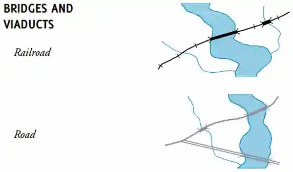
Linear Landmarks:
- Can be positively identified but not specifically plotted because they extend for some distance
- Features such as roads, railroads, coastlines, power lines and rivers may make good timing checkpoints if they are perpendicular to the course line and have other specific environmental particulars that identify your position [/////]
- Rivers and power lines must be easy to find, either isolated or large so they are unmistakable with confirming landmarks so they can be confirmed
- Railroads and major highways are almost always depicted on aeronautical charts
-
Uncertain Landmarks:
- Features that a pilot suspects he can correlate with the chart, but they may not be fully reliable
- Landmarks such as oil wells, and windmills may be repetitious
- Objects may look much alike
-
-
Spotting Landmarks:
- Landmarks may be hard to spot, but there are some tricks you can use:
- Offset to the landmark slightly to have better visibility out the side of the aircraft looking straight down
- Use Google Earn to spot nearby landmarks to reference when near
- Program the point into a GPS
- Landmarks may be hard to spot, but there are some tricks you can use:


Weather Planning
- Pilots are required to review official weather sources to make initial go/no-go decisions
Selecting Cruise Altitudes
- Altitude selection depends on a variety of factors which include:
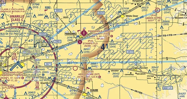
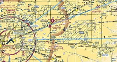
Terrain and Obstacles:
- Although seemingly obvious, controlled flight into terrain is still a leading caues of aviation accidents
- Terrain and obstacles along the route of flight must be avoided either laterally or vertically
- Additionally, a brief study of the map should highlight hazards should the pilot chose to alter the route, in flight
- Many structures exist that could significantly affect the safety of your flight when operating below 500' AGL and particularly below 200' AGL, despite FAR 91.119 allowing flight below 500' when over sparsely populated areas or open water. []
- Obstacles that extend more than 200 feet AGL are typically shown on sectional charts unless they are within the yellow tint of a city.
- At and below 200 feet AGL there are numerous power lines, antenna towers, etc., that are not marked and lighted and/or charted as obstructions and, therefore, may not be seen in time to avoid a collision.
- The FAA typically issues Notices to Airmen (NOTAMs) for unlit structures, but pilots must stay vigilant in case the FAA has not received outage notifications.
- Additionally, new obstructions may not be on current charts because the information was not received prior to the FAA publishing the chart.
-
Antenna Towers:
- Numerous skeletal structures, such as radio and television antenna towers, exceed 1,000' or 2,000' AGL.
- Guy wires support most skeletal structures, but they are challenging to see in good weather and can become invisible at dusk or during periods of reduced visibility.
- These wires can extend about 1,500 feet horizontally from a structure; therefore, all skeletal structures should be avoided horizontally by at least 2,000 feet.
-
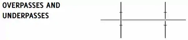
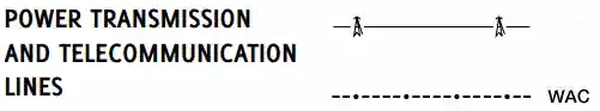
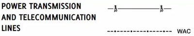
Overhead Wires:
- Transmission and utility lines often span areas used for runway approaches and natural flyways, such as lakes, rivers, gorges, and canyons. They also cross other landmarks pilots frequently follow, such as highways, railroad tracks, and other major transportation routes.
- As with antenna towers, these power transmission and/or utility lines and the supporting structures of these lines may not always be readily visible.
- The wires may be virtually impossible to see under certain conditions.
- Spherical markers may be used to identify overhead wires and catenary transmission lines and may be lighted.
- In some locations, the supporting structures of overhead transmission lines are equipped with unique sequence flashing white strobe light systems to indicate that there are wires between the structures.
- The flash sequence for the wire support structures will be middle, top, and bottom with all lights on the same level flashing simultaneously.
- However, not all power transmission and/or utility lines require notice to the FAA as they do not exceed 200 feet AGL or meet the obstruction standard of 14 CFR Part 77 and, therefore, are not marked and/or lighted.
- All pilots are cautioned to remain extremely vigilant for power transmission and/or utility lines and their supporting structures when following natural flyways or during the approach and landing phase.
- This is particularly important for seaplane and/or float equipped aircraft when landing on, or departing from, unfamiliar lakes or rivers.
-
Wind Turbines:
- Wind turbines are becoming increasingly prevalent as a component in the shift to renewable energy. []
- Wind turbines are typically below 500 feet, but some may be significantly higher, even encroaching into the 700 foot AGL floor of Class E airspace.
- The locations of wind turbine farms have also expanded to areas more commonly flown by VFR pilots and to all regions of the United States.
- VFR pilots should be aware that many wind turbines are exceeding 499 feet AGL in height, which may affect minimum safe VFR altitudes in uncontrolled airspace.
- Pilots are cautioned to maintain appropriate safe distance (laterally, vertically, or both).
- Wind turbines are typically charted on Visual Flight Rules (VFR) Sectional Charts and/or Terminal Area Charts.
- For a description of how wind turbines and wind turbine farms are charted, refer to the FAA Aeronautical Chart User's Guide.
- Wind turbines are normally painted white or light gray to improve daytime conspicuity.
- They are typically lit with medium−intensity, flashing red lights, placed as high as possible on the turbine nacelle (not the blade tips), that should be synchronized to flash together; however, not all wind turbine units within a farm need to be lighted, depending on their location and height.
- Sometimes, only the perimeter of the wind turbine farm and an arrangement of interior wind turbines are lit.
- Some wind turbine farms use Aircraft Detection Lighting Systems (ADLS), which are proximity sensor−based systems designed to detect aircraft as they approach the obstruction.
- This system automatically activates the appropriate obstruction lights until they are no longer needed based on the position of the transiting aircraft.
- This technology reduces the impact of nighttime lighting on nearby communities and migratory birds and extends the life expectancy of the obstruction lights.
- For more information on how obstructions such as wind turbines are marked and lighted, refer to Advisory Circular 70/7460−1, Obstruction Marking and Lighting.
- Pilots should be aware that wind turbines in motion could result in limitations of air traffic services in the vicinity of the wind turbine farms.
- Turbines or groups of turbines (1 out of 3 lights must illuminate) have red flashing lights placed on top of the turbine nacelle (note the blade is higher).
- Additionally, wind farms can produce reflectivity, producing returns on Doppler radar.
- Sectional charts depict wind farms with a boxed number indicating the maximum elevation figure.
-
Meterological (MET) Evaluation Towers:
- MET towers are used by wind energy companies to determine feasible sites for wind turbines.
- These structures are portable, erected in a matter of hours, installed with guyed wires, and constructed from a galvanized material often making them difficult to see in certain atmospheric conditions.
- Markings for these towers include alternating bands of aviation orange and white paint, and high−visibility sleeves installed on the outer guy wires.
- However, not all MET towers follow these guidelines, and pilots should be vigilant when flying at low altitude in remote or rural areas.
-
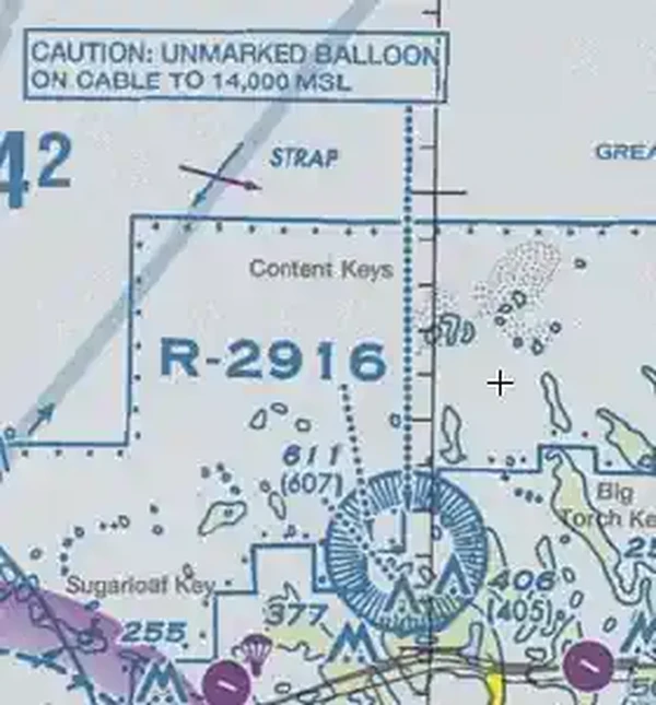
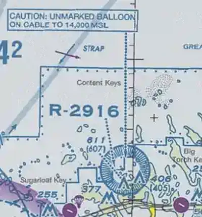
Unmanned Balloons:
- The majority of unmanned free balloons currently being operated have, extending below them, either a suspension device to which the payload or instrument package is attached or a trailing wire antenna, or both. []
- You can expect restricted airspace established in the vicinity of these balloons
- Good judgment on the part of the pilot dictates that aircraft should remain well clear of all unmanned free balloons and flight below them should be avoided at all times.
- Pilots are urged to report any unmanned free balloons sighted to the nearest FAA ground facility with which communication is established to assist FAA ATC facilities in identifying and flight following unmanned free balloons operating in the airspace.
- The majority of unmanned free balloons currently being operated have, extending below them, either a suspension device to which the payload or instrument package is attached or a trailing wire antenna, or both. []
-
Other Objects/Structures:
- There are other objects or structures that could adversely affect your flight such as temporary construction cranes near an airport, newly constructed buildings, new towers, etc.
- Many of these structures do not meet charting requirements or may not yet be charted because of the charting cycle.
- Some structures do not require obstruction marking and/or lighting, and some may not be marked and lighted even though the FAA recommended it.
- VFR pilots should carefully review NOTAMs for temporary or permanent obstructions along the planned route of flight during their preflight preparations.
- Particular emphasis should be given to obstructions in the vicinity of the approach and departure ends of the runway complex or any other areas where flight below 500 feet AGL is planned or likely to occur.
-
Glide Distance:
- The glide distance of the airplane is based on the glide ratio, a performance number to provide an idea of the options available in an engine out
- More than airports, suitable roads and fields options for emergency landings increases with increased altitude
- Additionally, regulatory requirements, such as those found in FAR 91.205, specify supplemental survival equipment depending on glide-distance from shore if the flight is conducted for hire
- Even further, FAR 91.509 further specifies supplemental survival equipment based on distance from shore
-
Effects of Winds:
- Winds are an important planning consideration both during terminal (surface winds) and cruise (winds aloft) environment.
-
Effects of Surface Winds:
- Surface winds are most commonly used for determining an optimal runway in the terminal area
- Similarly, surface winds provide insight into optimal landing surfaces in an emergency along a route of flight.
-
Effects of Winds at Cruise:
- Wind direction and intensity at various cruise altitudes are an important consideration to determine cruise performance
- Winds aloft are the most direct means to plan for winds at cruise altitudes along the route of flight
- Headwinds increase flight time and therefore fuel burn, reducing range, while tailwinds do just the opposite
- Further, headwinds require for power (increased fuel burn) and tailwinds decrease power requirements (decreased fuel burn)
-
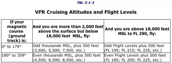
VFR Cruising Altitudes and Flight Levels:
- VFR Cruising Altitudes. [] are established to reduce mid-air collisions by establishing cruise altitudes governed by FAR 91.159 which states:
- Except while holding in a holding pattern of 2 minutes or less (see VFR Holding), or while turning, each person operating an aircraft under VFR in level cruising flight more than 3,000 feet above the surface shall maintain the appropriate altitude or flight level prescribed below, unless otherwise authorized by ATC:
- When operating below 18,000 feet MSL and:
- On a magnetic course of zero degrees through 179 degrees, any odd thousand foot MSL altitude + 500 feet (such as 3,500, 5,500, or 7,500); or
- On a magnetic course of 180 degrees through 359 degrees, any even thousand foot MSL altitude + 500 feet (such as 4,500, 6,500, or 8,500)
- When operating above 18,000 feet MSL, maintain the altitude or flight level assigned by ATC.
- When operating below 18,000 feet MSL and:
- Account for changes in direction of flight along a flight plan and corresponding altitude changes to meet the standard
- Except while holding in a holding pattern of 2 minutes or less (see VFR Holding), or while turning, each person operating an aircraft under VFR in level cruising flight more than 3,000 feet above the surface shall maintain the appropriate altitude or flight level prescribed below, unless otherwise authorized by ATC:
- ATC may give other restrictions if you are under their control, say with flight following or when within controlled airspace.
- IFR Cruising Altitudes can be found by referencing FAR 91.179
Memory Aids:
- The 13 Colonies (an odd number) were on the east coast of the U.S.
- Eastern states have odd shapes
- NEODD SWEVEN: North East Odd, South West Even
- VFR Cruising Altitudes. [] are established to reduce mid-air collisions by establishing cruise altitudes governed by FAR 91.159 which states:
-
Smooth of Rough Air:


Determining Headings/Courses
- Once a route has been chosen, you need to calculate headings/courses to be flown
- The two terms, often used interchangeably, in fact mean different things:
- Courses are the direction which the aircraft is actually traveling (impacted by winds)
- Headings are the directions which the aircraft faces (where it is pointed)
-
Wind Correction Angle:
- Find your winds aloft through an official weather source.
- Plot the winds on your E6B Flight Computer:
- Place the wind direction under the "True Index" arrow
- Using a reference line on the E6B scale, measure up and plot the velocity
- Rotate the compass rose until your True Course is under the True Index pointer
- Move the entire compass until the plot is over your True Airspeed
- Note which side of the True Index the plot falls, and by how much based on the scale provided
- This is your wind correction angle
- If it is located on the left of the line, it must be subtracted from the True Course
- If it is located on the right of the line, it must be added to the True Course
- Heading/courses can be expressed as either true or magnetic
-
True Courses and Headings:
- True north is the basis by which true courses are measured and true headings are calculated against
-
True North Defined:
- True north is the direction along the earth's surface towards the geographic North Pole
- It is the northerly point furthest from the equator (90°N)
- True headings can therefore be measured on most aeronautical maps, including sectionals, by reference to true north.
-
Measuring True Course:
- Draw a straight line between two points (airports, checkpoints, etc.) on a sectional chart
- Next find the lines of longitude on a map
- Grab your plotter and place the reference hole over the intersection of the line of longitude
- Rotate the plotter so that it is parallel to the line you drew
- Where the line of longitude intersects the compass rose on the plotter, determine your true course
- If there is more than one number, chose the number most appropriate for your direction of flight.
-
Calculating True Heading:
- First, determine your wind correction angle
- Finally, apply the formula:
- True Heading = True Course (-left/+right) WCA
-
Magnetic Courses and Headings:
- As with true north, magnetic north is the basis by which magnetic courses and magnetic headings are calculated against
-
Magnetic North Defined:
- Magnetic north is the direction along the earth's surface which points toward the magnetic north pole
- Magnetic compasses point to this location and therefore it is magnetic headings that are flown
- The magnetic north pole is a shifting point which is not coincident with the "top" of the earth as defined by latitude and longitude.
-
Calculating Magnetic Course:
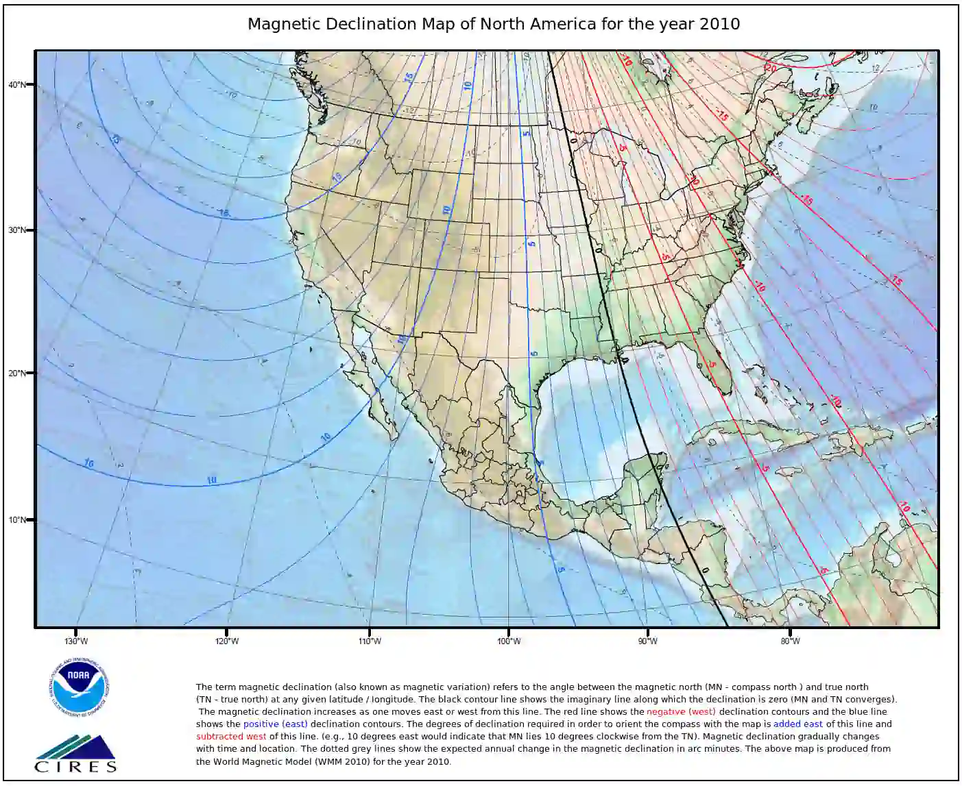
- Magnetic heading will usually require a correction based on the variation or:
- The angular difference between true north and magnetic north from any given position on the earth's surface (represented by isogonic lines)
- Isogonic lines are points of equal variation, represented in degrees east or west
- Deviations is usually pulled off a sectional chart however, other sources such as NOAA can provide this information
- The memory aide "east is least (minus), west is best (plus)" is often used to remember how to apply east and west variations
- Magnetic Course (MC) = True Course (TC) - East Variation
- Magnetic Course (MC) = True Course (TC) + West Variation.
- Magnetic heading will usually require a correction based on the variation or:
-
Calculating Magnetic Heading:
- All aircraft will have a deviation factor that must be applied
- Deviation is read off the compass card in the aircraft, and must be added or subtracted to the magnetic course as appropriate
Determining True Winds
- Determining winds at altitude help guide your true heading
- Since winds aloft are expressed in "true," you will calculate the wind correction angle off true course
Determining Deviation
- Deviation is found on a placard with your magnetic compass
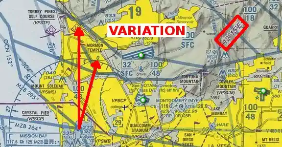
Determining Variation
- Variation is necessary for converting true headings to magnetic
- Magnetic variation depends on your location on the earth, as labeled by isogonic lines
Determining Compass Heading
- Compass heading is determined by applying the deviation correction to the magnetic heading
Top of Climb
- Given:
- Departure Airport: 900 ft
- Cruise Altitude: 5,500 ft
- From Sea Level to 5,500' we calculate 9 minutes, 2.0 Gal, 13 NM
- Assuming 1,000' for the departure altitude we calculate: 1 minute, 0.4 Gal, 2 NM
- Subtract the difference: (9-1)=8 Min, (2.0-0.4)=1.6 Gal, (13-2)=11 NM
- Pay attention to the notes at the bottom of the chart, especially to add 1.1 Gal for taxi and takeoff
Time, Distance, and Speed Calculations
- Utilizing a simple formula (Distance = Time x Ground Speed may be utilized
- Therefore, if you have any two, you can calculate the other
-
Time Calculations:
- If you need to travel 10 NM, and you have a ground speed of 100 knots, how long will it take?
- 10 NM = Time (hours) x 100
- 10/100 = Time
- Time = 0.1
- Multiply 0.1 by 60 (minutes in an hour) and you'll get 6, for 6 minutes to travel that distance at that ground speed
- As wind gets factored in, even if a round trip with consistent winds, the time to fly becomes longer - headwinds/tailwinds will not cancel out (see: Is time lost fighting a headwind gained back when riding a tailwind?)
- Suppose D = distance, TT = total time, AS = air speed, WS = wind speed.
- Then the equation for a direct headwind and tail wind is TT = D/(AS - WS) + D/(AS + WS) = 150/(100 - 50) + 150/(100 + 50) = 150/50 + 150/150 = 450/150 + 150/150 = 600/150 = 4.
- With WS = 0 the equation becomes TT = 150/100 + 150/100 = 300/100 = 3
- In total, adding each leg, accounting for climb/descent, produces the time enroute.
-
Zulu Time Converstions:
- Zulu time, also referred to a Greenwich Mean Time (GMT) is the standard time for all of aviation
- Many website and applications will help pilots calculate these times, which become important when trying to normalize timezones and input departure and arrival times when filing a flight plan
- To calculate, determine timezone correction and add (western hemisphere) or subtract (eastern hemisphere) to/from zulu time
- If you need to travel 10 NM, and you have a ground speed of 100 knots, how long will it take?
-
Distance Calculations:
- Distance is rate time time
- You will travel 10% of speed in 6 minutes
- If you are traveling at 100 knots ground speed for 6 minutes, how far will you travel?
- Distance = 0.1 (see above) x 100
- Distance = 10 NM
- Using an E6B:
- Point to ground speed with the arrow
- Find time and read above
- For times under 3 minutes, the small arrow may need to be utilized
Descent Planning
- Planning for descent ensures the accurate and timely arrival at the desired space in time, generally to set up for landing
- Pilots often chose between maintaining power in the descent, pitching forward for a faster airspeed or reducing power in the descent, maintaining a desired airspeed
- While differences in aircraft, avionics, and technique flown, the 60:1 rule allows for basic in-flight calculations in preparation for descent
-
Descent Planning With The 60-to-1 Rule:
- The 60 to 1 rule states for every 1 degree of shift (up/down/left/right), an offset of 100 feet per 1 Nautical Mile (NM) occurs
- As it relates to descent planning, this means for every 1 degree the pitch is lowered (relative to level flight), you will lose 100 feet every NM.
-
Practical Application:
- Example: A pilot is 20 NM away from an airport at 6,000' MSL to enter the downwind at 1000' Mean Sea Level (MSL)
-
Determining Pitch Angle:
- We have 5,000' to lose over 20 NM
- If we take the altitude to lose and divide it by the distance (5,000'/20NM), we see that we need to lose 250 feet every 1 NM
- Referencing the 60-to-1 rule, if a 1-degree pitch down is 100' per 1 NM, then a 2.5-degree pitch down is 250' per 1 NM.
-
Determining Vertical Speed:
- We determined that our pitch must be 2.5 degrees down, and since we're flying at some constant speed, this translates to a predictable vertical speed, which we can calculate
- If you multiply the descent angle (2.5 degrees in the above example) by the Nautical Miles-per-minute and then multiply that number by 100, you get the Feet Per Minute (FPM) descent rate
- Shown another way: (NM per Min * Pitch down * 100 = Descent in Feet per Minute)
- First, determine nautical miles per minute:
- Divide the airspeed (NM per Hour) by 60 (Minutes per hour) to get Nautical Miles per minute
- If we intend to descend at 90 knots, we divide that by 60 and get 1.5 NM per minute
- Second, determine vertical speed:
- If we then multiply our NM per minute by our pitch-down of 2.5 degrees, we get 3.75
- Multiply 3.75 by 100, and you get 375 feet per minute
- Another way of doing the same thing is knowing we have 20 NM to travel at 1.5 NM/Minute; we can determine that we have approximate 13 minutes to lose 5,000 feet
- 5000 divided by 13 = 384 FPM
-
Working Backwards:
- We can work backward too, for example, let's say we wish to descend at 200 FPM for passenger comfort
- If we are traveling at 1.5 NM per minute, and we have 5,000' to lose at 200 FPM, it will take 25 minutes to accomplish this descent (5,000'/200 FPM)
- Since we calculated ~375 FPM was required for being 20 NM out, and we plan to reduce our rate of descent, we need to begin descending earlier
- Assuming we are flying at 1.5 NM per minute, and we need 25 minutes to descend, we need to begin our descent at 37.5 NM away (25* 1.5)
- Additionally, instrumentation may display how far away the aircraft is from a known point
- If instrumentation displays 5 minutes to a point, and the pilot needs to descend 1000' in that time, then feet (1,000) divided by minutes (5) equals the required feet per minute, in this case 200, feet per minute
- If we are traveling at 1.5 NM per minute, and we have 5,000' to lose at 200 FPM, it will take 25 minutes to accomplish this descent (5,000'/200 FPM)
- Note the 60-to-1 rule is a rule of thumb and not an exact science, but accurate enough to guide basic decisions and cross-check expected performance. []
- When flying a non-precision approach, a Vertical Descent Angle (VDA) and Threshold Crossing Height (TCH) may be published. For Copter approach procedures, a Heliport Crossing Height (HCH) will be depicted in place of the TCH. The VDA is strictly advisory and provides a means to establish a stabilized descent to the Minimum Descent Altitude (MDA). The presence of a VDA does not guarantee obstacle protection in the visual segment. If there are obstacles in the visual segment that could cause an aircraft to destabilize the approach between MDA and touchdown, the profile will not show a VDA and will instead show a note that states "Visual Segment-Obstacles". []
- When descending to MDA, consider the time desired to level-off and stabilize to see the landing environment and "break out" to land
- Pay attention to shock cooling, whereby operations at a lower engine setting for extended periods can quickly cool an engine
- Bold Method as several great articles that discuss descent planning to include: "How the 60-1 rule helps you plan a perfect descent and know when to reduce the throttle when given a "descent at pilot's discretion" and "How To Calculate Your Descent Rate To MDA".
- We can work backward too, for example, let's say we wish to descend at 200 FPM for passenger comfort
-
Rule of 3:
- Take the thousands of feet required to descend and multiply by 3 provides the distance at which a pilot must begin descent if at about a 3 degree slope.
-
Quick Math:
- If you know the altitude you want to lose in total (i.e., 6,500 ft), simply divide by 1000 for 1000 FPM descent, giving 6.5 minutes.
- Double the time if considering a 500 FPM descent.
-
Inducation System Performance:
- On normaly aspirated engines, climbing/descending changes the mixture received by the engine given the changing air density.
- Specifically during descent, the air becomes more dense leading to the mixture becoming leaner.
- Engine temperature will rise if the mixture becomes too lean, potentially leading to decreased performance, increased oil consumption, and detonation
- When operating at low power settings in the descent (i.e., pulling power to descend), pilots should richen the mixture as necessary to maintain smooth operation.
- This is especially true for those operating lean of peak during cruise.
- When operating at higher power settings in the descent (i.e., nosing over to descend), pilots should proactively richen the engine during the descent to maintain the higher engine performance demanded.
- This is especially true for those operating rich of peak (best economy).

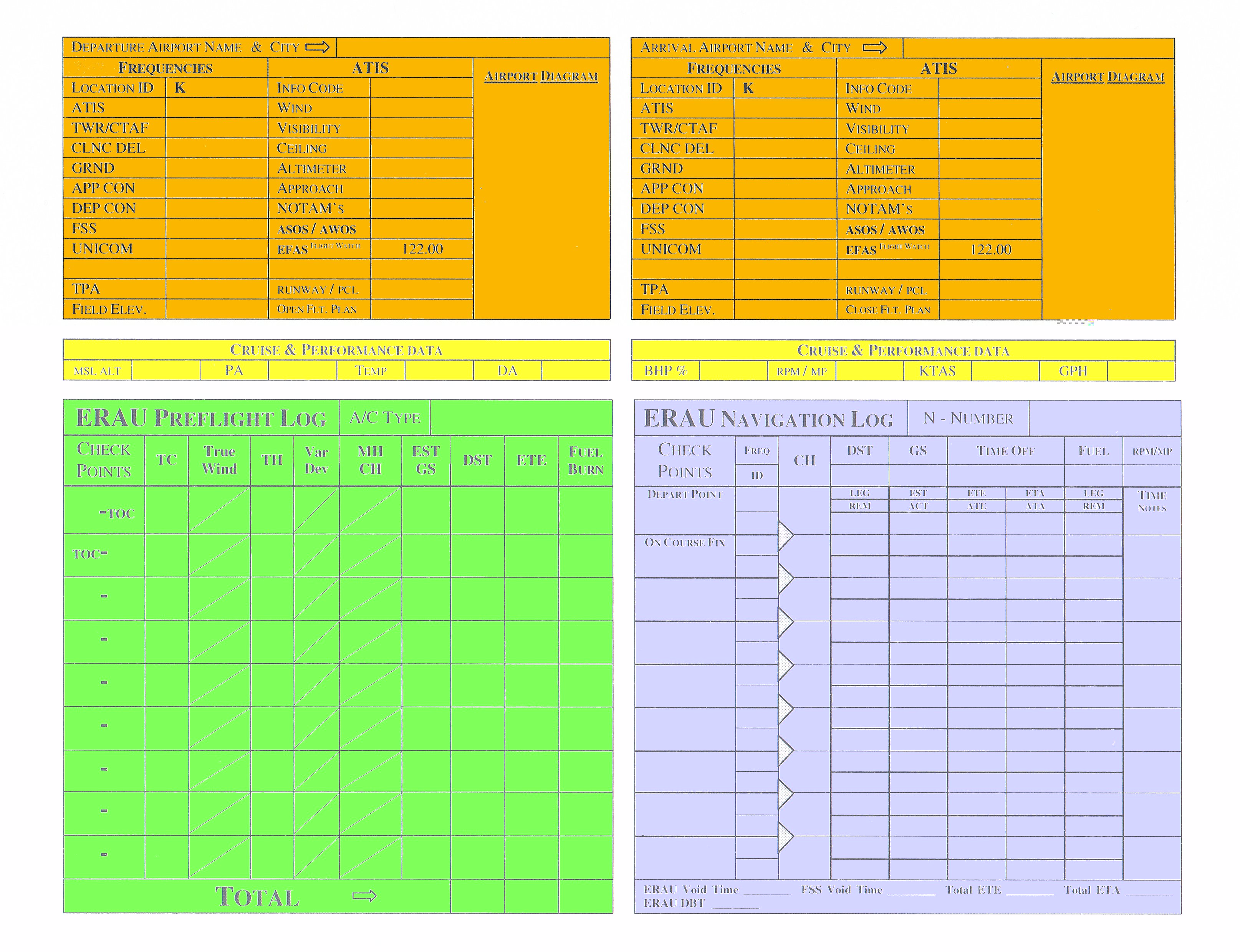
Completing a NAVLOG
- Navigation logs, or NAVLOGs, is the printed, either physically or digitally, plan
- This plan accounts for the environment's effects on the aircraft, as well as aircraft anomalies like deviation
- NAVLOGs come in many forms and there is no perfect form; its about personal preference
- An example of a generic NAVLOG is provided below: [/]
- ORANGE Section
- Fill out the departure and arrival airport information including frequencies, traffic altitudes, and heights above ground
- Fill in information concerning flight service or any item you will want to reference in regards to that airport
- If you want, draw an airport diagram in the box but still carry a larger printed diagram for easier use and more detail
- YELLOW Section
- Determine a MSL cruise altitude based on weather and direction of flight
- Reference above diagram
- Calculate pressure altitude for your airport (important for performance calculations)
- Determine the temperature (important for performance calculations)
- Calculate density altitude (important for performance calculations)
- Determine a horsepower setting and the accompanying RPM settings, KTAS and Gallons per Hour
- GREEN Section
- Write in the aircraft type
- Used to plot any changes to a heading for the entire route to estimate times, distances and fuel used
- True Course (TC): found on sectional using plotter
- True Wind: found on winds aloft forecasts
- True Heading (TH): calculated with flight computer (back of flight calculator)
- Variation (Var): simply the difference between true north and magnetic north, found on sectional for your route. []
- Deviation (Dev): found on the compass card in your aircraft. []
- Magnetic Heading (MH): TH corrected for variation
- Course Heading (CH): MH corrected for deviation
- Ground Speed (EST GS): found under the grommet when calculating wind correction angle
- Distance (DST): calculated with POH and Plotter on the sectional
- Estimated Time En-route (ETE): calculated with flight computer (arrow on GS, time read under distance)
- Fuel Management:
- Fuel Planning calculated with flight computer (arrow on GPH, read under time)
- SETTO: Startup, Taxi and Takeoff lost fuel, usually 1.4 Gal
- Total: Add everything up, this is a rough estimate for the flight, you will only use this section for planning on the ground
- BLUE Section
- Write aircraft tail number
- List all checkpoints and associated distances
- Write in any frequencies or IDs for route navigation
- CH can be copied from the preflight log
- Distance is measured off the sectional
- GS (first or second line only): copy from preflight log
- ETE: calculate same as preflight log
- Fuel: calculate same as preflight log
- In flight you will be filling in the other boxes as the flight progresses
- ORANGE Section
- Weight and balance as calculated normally
- YELLOW Section
- Fill out any weather information or notes you may have
- Check NOTAMs for the route of flight
- GREEN Section
- Fill out the flight plan for flight service
- All information is from the front of the navigation log
- Filed before flight with the FSS so they can keep a track of you. If you do not close the flight plan 30 minutes after the proposed arrival time, SAR (search and rescue) procedures begin
- BLUE Section
- Fill out airspeeds, runway lengths, and altitudes
- RED Section
- VFR Cross-Country Checklist. []
- Make sure all items are complete
- ORANGE Section

Inflight Guides
- After you've completed your flight log, consider the creation of an inflight guide to keep on your kneeboard during flight
- This inflight guide is not intended to create an extra step in flight planning but instead to make your life easier when you're flying
- Contents might include:
- Print outs of the local airport information from the Chart Supplement U.S.
- NOTAMS
- etc.
Private Pilot (Airplane) Pilotage and Dead Reckoning Airman Certificaton Standards
- Objective: To determine whether the applicant exhibits satisfactory knowledge, risk management, and skills associated with pilotage and dead reckoning
- References: FAA-H-8083-2 (Risk Management Handbook), FAA-H-8083-3 (Airplane Flying Handbook), FAA-H-8083-25 (Pilot Handbook of Aeronautical Knowledge); VFR Navigation Charts
- Private Pilot (Airplane) Pilotage and Dead Reckoning Lesson Plan.
Private Pilot (Airplane) Pilotage and Dead Reckoning Knowledge:
The applicant demonstrates an understanding of:-
PA.VI.A.K1:
Pilotage and dead reckoning. -
PA.VI.A.K2:
Magnetic compass errors. -
PA.VI.A.K3:
Topography. -
PA.VI.A.K4:
Selection of appropriate:-
PA.VI.A.K4a:
Route. -
PA.VI.A.K4b:
Altitude(s). -
PA.VI.A.K4c:
Checkpoints.
-
-
PA.VI.A.K5:
Plotting a course, to include:-
PA.VI.A.K5a:
Determining heading, speed, and course. -
PA.VI.A.K5b:
Wind correction angle. -
PA.VI.A.K5c:
Estimating time, speed, and distance. -
PA.VI.A.K5d:
True airspeed and density altitude.
-
-
PA.VI.A.K6:
Power setting selection. -
PA.VI.A.K7:
Planned versus actual flight plan calculations and required corrections.
Private Pilot (Airplane) Pilotage and Dead Reckoning Risk Management:
The applicant is able to identify, assess, and mitigate risks associated with:-
PA.VI.A.R1:
Collision hazards. -
PA.VI.A.R2:
Distractions, task prioritization, loss of situational awareness, or disorientation.
Private Pilot (Airplane) Pilot and Dead Reckoning Skills:
The applicant exhibits the skills to:-
PA.VI.A.S1:
Prepare and use a flight log. -
PA.VI.A.S4:
Use the magnetic direction indicator in navigation, including turns to headings. -
PA.VI.A.S5:
Verify position within three nautical miles of the flight-planned route. -
PA.VI.A.S6:
Arrive at the en route checkpoints within five minutes of the initial or revised estimated time of arrival (ETA) and provide a destination estimate. -
PA.VI.A.S7:
Maintain the appropriate altitude ±200 feet and heading ±15°.
Private Pilot (Airplane) Cross-Country Flight Planning Airman Certification Standards
- Objective: To determine whether the applicant exhibits satisfactory knowledge, risk management, and skills associated with cross-country flights and VFR flight planning
- References: 14 CFR part 91; AIM; Chart Supplements; FAA-H-8083-2 (Risk Management Handbook), FAA-H-8083-3 (Airplane Flying Handbook), FAA-H-8083-25 (Pilot Handbook of Aeronautical Knowledge); NOTAMs; VFR Navigation Charts
- Note: Preparation, presentation, and explanation of a computer-generated flight plan is an acceptable option
- Private Pilot Cross-Country Flight Planning Lesson Plan.
Private Pilot (Airplane) Cross-Country Flight Planning Knowledge:
The applicant demonstrates an understanding of:-
PA.I.D.K1:
Route planning, including consideration of different classes and special use airspace (SUA) and selection of appropriate and available navigation/communication systems and facilities.-
PA.I.D.K1a:
Use of an electronic flight bag (EFB), if used.
-
-
PA.I.D.K2:
Altitude selection accounting for terrain and obstacles, glide distance of airplane, VFR cruising altitudes, and effect of wind. -
PA.I.D.K3:
Calculating:-
PA.I.D.K4:
Time, climb and descent rates, course, distance, heading, true airspeed, and groundspeed. -
PA.I.D.K3b:
Estimated time of arrival, including conversion to universal coordinated time (UTC). -
PA.I.D.K3c:
Fuel requirements, including reserve.
-
-
PA.I.D.K4:
Elements of a VFR flight plan. -
PA.I.D.K5:
Procedures for filing, activating, and closing a VFR flight plan. -
PA.I.D.K6:
Inflight intercept procedures.
Private Pilot (Airplane) Cross-Country Flight Planning Risk Management:
The applicant is able to identify, assess, and mitigate risks associated with:-
PA.I.D.R1:
Pilot. -
PA.I.D.R2:
Aircraft. -
PA.I.D.R3:
Environment (e.g., weather, airports, airspace, terrain, obstacles). -
PA.I.D.R4:
External Pressures. -
PA.I.D.R5:
Limitations of air traffic control (ATC) services. -
PA.I.D.R6:
Fuel planning. -
PA.I.D.R7:
Use of an electronic flight bag (EFB), if used.
Private Pilot (Airplane) Cross-Country Flight Planning Skills:
The applicant exhibits the skills to:-
PA.I.D.S1:
Prepare, present, and explain a cross-country flight plan assigned by the evaluator, including a risk analysis based on real-time weather, to the first fuel stop. -
PA.I.D.S2:
Apply pertinent information from appropriate and current aeronautical charts, Chart Supplements; Notices to Air Missions (NOTAMs) relative to airport, runway and taxiway closures; and other flight publications. -
PA.I.D.S4:
Recalculate fuel reserves based on a scenario provided by the evaluator. -
PA.I.D.S5:
Use of an electronic flight bag (EFB), if used.
Instrument Rating - Cross-Country Flight Planning Airman Certification Standards
- Objective: To determine whether the applicant exhibits satisfactory knowledge, risk management, and skills associated with planning an IFR cross-country and filing an IFR flight plan
- Note: Preparation, presentation, and explanation of a computer-generated flight plan is an acceptable option
- References: 14 CFR part 91; AIM; Chart Supplements; FAA-H-8083-2 (Risk Management Handbook), FAA-H-8083-3 (Airplane Flying Handbook), FAA-H-8083-15, FAA-H-8083-16, FAA-H-8083-25 (Pilot Handbook of Aeronautical Knowledge); IFR Enroute Charts; NOTAMs; IFR Navigation Charts
- Instrument Rating - Cross-Country Flight Planning Lesson Plan.
Instrument Rating - Cross-Country Flight Planning Knowledge:
The applicant demonstrates an understanding of:.-
IR.I.C.K1:
Route planning, including consideration of:.-
IR.I.C.K1b:
Special use airspace. -
IR.I.C.K1c:
Preferred routes. -
IR.I.C.K1d:
Primary and alternate airports. -
IR.I.C.K1e:
Enroute charts. -
IR.I.C.K1f:
Chart Supplements. -
IR.I.C.K1g:
NOTAMS. -
IR.I.C.K1h:
Terminal Procedures Publications (TPP).
-
IR.I.C.K2:
Altitude selection accounting for terrain and obstacles, glide distance of airplane, IFR cruising altitudes, effect of wind, and oxygen requirements. -
IR.I.C.K3:
Calculating:.-
IR.I.C.K3a:
Time, climb and descent rates, course, distance, heading, true airspeed, and groundspeed. -
IR.I.C.K3b:
Estimated time of arrival to include conversion to universal coordinated time (UTC). -
IR.I.C.K3c:
Fuel requirements, including reserve.
-
-
IR.I.C.K4:
Elements of an IFR flight plan. -
IR.I.C.K5:
Procedures for activating and closing an IFR flight plan in controlled and uncontrolled airspace.
Instrument Rating - Cross-Country Flight Planning Risk Management:
The applicant is able to identify, assess, and mitigate risks associated with:-
IR.I.C.R1:
Pilot -
IR.I.C.R2:
Aircraft. -
IR.I.C.R3:
Environment (e.g., weather, airports, airspace, terrain, obstacles). -
IR.I.C.R4:
External pressures. -
IR.I.C.R5:
Limitations of air traffic control (ATC) services. -
IR.I.C.R6:
Limitations of electronic planning applications and programs. -
IR.I.C.R7:
Fuel planning.
Instrument Flight - Cross-Country Flight Planning Skills:
The applicant exhibits the skills to:-
IR.I.C.S1:
Prepare, present, and explain a cross-country flight plan assigned by the evaluator including a risk analysis based on real time weather, which includes calculating time en route and fuel considering factors such as power settings, operating altitude, wind, fuel reserve requirements, and weight and balance requirements. -
IR.I.C.S2:
Recalculate fuel reserves based on a scenario provided by the evaluator. -
IR.I.C.S4:
Interpret departure, arrival, en route, and approach procedures with reference to appropriate and current charts. -
IR.I.C.S5:
Recognize simulated wing contamination due to airframe icing and demonstrate knowledge of the adverse effects of airframe icing during pre-takeoff, takeoff, cruise, and landing phases of flight as well as the corrective actions. -
IR.I.C.S6:
Apply pertinent information from appropriate and current aeronautical charts, Chart Supplements; Notices to Air Missions (NOTAMs) relative to airport, runway and taxiway closures; and other flight publications.
Flight Planning Lessons & Case Studies
- National Transportation Safety Board (NTSB) Identification: SEA08LA054:
- The NTSB determines the probable cause(s) of this accident to be: The loss of engine power due to fuel exhaustion. Contributing to the accident was the lack of suitable terrain for the forced landing
Flight Planning Knowledge Check


Flight Planning Conclusion
- Planning is based on what we believe will occur
- It may be incorrect and calculations/adjustments may need to be made in flight, but having a point from which to depart leads to educated decisions
- The military calls this mission cross-check
- When dead reckoning, you've done the math to determine timing, and so if you arrive at a checkpoint according to timing and direction but you don't see it, turn to your next heading and orient yourself
- Information to aircraft performance at various altitudes can be found in Chapter 5 of the Pilot Information Manual
- Navigation should always be done from the chart to the landmarks
- This means look at your chart first and then at the ground for your landmark
- If done the other way around you could find yourself staring at your map looking for a landmark that may not be charted
- There is no correct cruise altitude, its a balance of terrain and obstacles, glide distances, winds, required VFR cruising altitudes and flight levels, and smoothness of air
- Remember that documents may not reflect reality and when it comes to services available at an airport, they may not be available due to supplies or even destructive weather
- It is advised that you call FBOs ahead of departures to ensure required services are available
- Don't forget about what you want to do after you reach your destination
- Chose an Fixed-Based Operator (FBO) ahead of landing and give them a call before you depart to ensure the desired services will be available, where you must go to receive them (i.e., fuel farms may not be at the FBO ramp), and any special parking instructions
- When planning fuel stops per VFR/IFR requirements, consider FBO hours, services, etc.
- When traveling cross-country, it is recommended to carry extra closes/toiletries (bingo bag) to mitigate comfort-based delays when making diversion decisions.
- Pilots should consider the implications of planning or filing/requesting direct legs
- This includes terrain, navaid coverage, emergency options, etc.
- Weather products like windy.com offer additional insight into aviation weather forecasts and observations
- Don't forget to check SAFOs.
- Remember mountain flying considerations
- A member of the AOPA? Try their flight planner.
- See also:
- Review your flight planning safety knowledge by taking the Air Safety Institute's "A Visit to the Grey Lady" quiz
- Still looking for something? Continue searching:
Flight Planning References
- Federal Aviation Administration - Pilot/Controller Glossary.
- Aeronautical Information Manual (3-1-5) VFR Cruising Altitudes and Flight Levels.
- Aeronautical Information Manual (7-6-4) Obstructions To Flight.
- Aeronautical Information Manual (7-6-5) Avoid Flight Beneath Unmanned Balloons.
- AOPA - Flight Tools.
- ERAU Basic Flight Plan Page 1.
- ERAU Basic Flight Plan Page 2.
- Generic Flight Plan.
- SkyVector.
- FltPlan
- 1800wxbrief.com
- ForeFlight
- FltplanGo
- RunwayFinder
- Pilot Workshops - Finding the Airport.
- FAA - ICAO FPL Quick Guide (2019).
- AeroNav Chart Users Guide.
- Federal Aviation Regulations (91.119) Minimum safe altitudes: General.