Turn Coordinator
Learn how a turn coordinator shows roll rate, turn rate, and coordination; interpret standard-rate indications, verify operation, and recognize failures.
Introduction to Turn Coordinator
- Turn coordinators display the rate of turn and roll information.
- The gyroscope provides rate information, while the separate inclinometer ball indicates turn coordination.
- Check the instrument during startup and taxi to verify proper operation.
- Electronic flight displays may obtain turn and coordination information from integrated sensors; consult the installed system's documentation and the Inertial Reference Unit (IRU), Inertial Navigation System (INS), and Attitude and Heading Reference System (AHRS) discussion below.
- As with any system or instrument, anomalies and malfunctions are possible, requiring detailed knowledge of the indicator and related systems.
- Reinforce your understanding of Turn Coordinator by completing the knowledge quiz and interactive scenario, comparing your performance with the applicable Airman Certification Standards, and reviewing the topic summary before moving on.
Turn Coordinator Key Highlights
- The turn coordinator displays aircraft rate of turn and roll information during flight operations.
- Turn coordinators use gyroscopic principles to sense both roll initiation and turning motion.
- The miniature aircraft symbol indicates the direction and rate of turn relative to standard-rate turn markings.
- Standard-rate turns normally result in a heading change of approximately three degrees per second.
- The inclinometer, or slip-skid indicator, helps pilots maintain coordinated flight by showing balance between centrifugal force and gravity.
- An aircraft in coordinated flight keeps the inclinometer ball centered during turns and maneuvering operations.
- Turn coordinators are especially important during instrument flight and reduced-visibility conditions.
- Vacuum system failures or electrical malfunctions may affect turn coordinator operation depending on aircraft design.
- Pilots should cross-check turn coordinator indications with other flight instruments to maintain proper aircraft control.
- Understanding turn coordinator operation improves instrument proficiency, coordinated flight control, and overall flight safety.
Turn Coordinator Design and Function
- A turn coordinator uses a canted gyroscope to sense roll and turn rate. []
- The gimbal frame is angled upward about 30° from the aircraft's longitudinal axis, allowing the gyro to respond to both roll and yaw.
- Depending on the installation, the gyro may be electrically powered or driven by vacuum or pressure airflow.
- The turn coordinator developed from the turn-and-slip indicator, also called the turn-and-bank indicator.
- Aircraft rotation produces gyroscopic precession, which deflects the gyro and gimbal to drive the turn indication.
- A calibrated spring opposes gimbal deflection so the stabilized indication corresponds to turn rate.
- A visible power or warning flag, when fitted, indicates a condition requiring attention under the instrument's operating instructions.
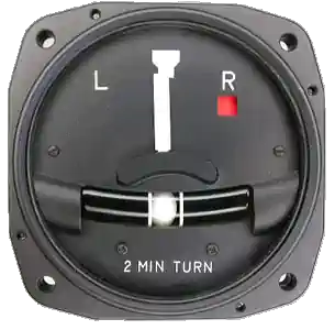
- The inclinometer ball below the miniature aircraft shows whether the turn is coordinated; it does not directly measure bank angle or turn rate.
- The 2 MIN marking means that a steady turn at the marked rate completes 360° in two minutes.
- The ball responds to the combined effects of gravity and acceleration; it is mechanically independent of the gyro.
- The gyro-operated turn indication relies on controlled precession.
- The left and right turn-index marks identify the instrument's calibrated turn rate.
- The canted mounting allows the instrument to respond promptly to roll as the aircraft enters or leaves a turn.
- In the older turn-and-slip indicator, the gyro has a lateral spin axis and a single gimbal aligned with the aircraft's longitudinal axis.
- Slip: the turn rate is too slow for the bank angle, and the ball moves toward the inside of the turn.
- Skid: the turn rate is too great for the bank angle, and the ball moves toward the outside of the turn.
- The older turn-and-slip indicator shows turn rate with a needle and coordination with a separate ball. []
- Its gimbal arrangement responds to yaw rather than roll.
- The needle shows direction and rate of turn; it does not display bank angle or pitch attitude.


Turn Coordinator Indications
- The miniature aircraft precisely shows roll response and turn rate, while the ball shows coordination.
- Interpret the turn indication as follows:
- With the aircraft no longer rolling, a centered indication shows no indicated turn rate.
- In a stabilized turn, aligning the miniature aircraft's wing with a turn-index mark on a two-minute turn coordinator indicates a standard-rate turn.
- A standard-rate turn changes heading at 3° per second.
- Standard rate remains 3° per second; higher true airspeed requires more bank to maintain that rate in a coordinated level turn.
- A rule of thumb for standard-rate-turn bank angle is (true airspeed in knots ÷ 10) + 7, in degrees.
- This is an approximation; use the turn-rate indication to establish the required rate.
- A turn coordinator responds to roll and turn rate; its deflection does not directly measure bank angle.
- Use the appropriate attitude reference for bank and the turn indication to cross-check the turning response.
Turn Coordinator Regulations
- A gyroscopic rate-of-turn indicator and a slip-skid indicator are required for IFR operations under 14 CFR 91.205(d)(3) and (4) for powered civil aircraft with standard U.S. airworthiness certificates, subject to the specified rate-of-turn indicator exceptions.
- A turn coordinator with an inclinometer provides both indications.
- The rate-of-turn indicator represents the first R in GRABCARDD, and the slip-skid indicator (ball) represents the B.
- The rate-of-turn indicator may be omitted when a qualifying third attitude instrument system meets the airplane or rotorcraft installation requirements specified in 14 CFR 91.205(d)(3).
- This exception does not remove the separate slip-skid indicator requirement.
- Neither instrument is required by the basic day or night visual flight rules (VFR) equipment list in 14 CFR 91.205.
- Aircraft certification, operating limitations, equipment lists, or other operating rules may nevertheless require them.
Turn Coordinator Preflight Actions
- After applying the instrument's power source and allowing the gyro to reach operating speed, verify that any power or warning flag clears as specified by the manufacturer.
- During taxi turns, the miniature aircraft should deflect toward the turn, while the inclinometer ball moves toward the outside of the turn.
Inertial Reference Unit (IRU), Inertial Navigation System (INS), and Attitude Heading Reference System (AHRS)
- Glass flight decks may integrate IRU, INS, and AHRS information with air-data inputs; consult the installed system's documentation to identify the source of each indication.
- An electronic attitude display commonly receives information from an Attitude and Heading Reference System (AHRS); other installations may use an Inertial Reference Unit (IRU) or Inertial Navigation System (INS).
- IRUs are self-contained systems comprised of gyros and accelerometers that provide aircraft attitude (pitch, roll, and heading), position, and velocity information in response to signals resulting from inertial effects on system components.
- Once aligned with a known position, IRUs continuously calculate position and velocity. IRU position accuracy decays with time.
- This degradation is known as "drift."
- INSs combine the components of an IRU with an internal navigation computer.
- By programming a series of waypoints, these systems will navigate along a predetermined track.
- AHRSs are electronic devices that provide attitude information to aircraft systems such as weather radar and autopilot, but do not directly compute position information.
- Aircraft equipped with slaved compass systems may be susceptible to heading errors caused by exposure to magnetic field disturbances (flux fields) found in materials that are commonly located on the surface or buried under taxiways and ramps.
- These materials generate a magnetic flux field that can be sensed by the aircraft's compass system flux detector or "gate", which can cause the aircraft's system to align with the material's magnetic field rather than the earth's natural magnetic field.
- The system's erroneous heading may not self-correct.
- Before takeoff, check for heading misalignment that may have developed during taxi.
- Correct any heading misalignment using the manufacturer's or other applicable procedures before takeoff.
Operating Considerations:
- Aircraft may have one or more AHRS units, depending on the installed avionics configuration.
- Verify the installed configuration using the aircraft's Pilot's Operating Handbook/Airplane Flight Manual, applicable avionics supplements, and equipment list.
- Consult the applicable avionics pilot's guide to identify sensor-selection controls and source annunciations, such as AHRS 1 and AHRS 2, when provided.
- Two displays do not necessarily mean two independent AHRS sources; both displays may receive information from the same unit.
- Know which source supplies each display and follow the aircraft-specific procedures for a failed or disagreeing source.
- Complete initialization and alignment before relying on the indications, following the installed equipment's procedures.
- Do not assume every system permits the same aircraft movement or in-flight realignment conditions.
- The following failure examples apply to the legacy Cessna Nav III G1000 with GRS 77 AHRS shown above.
- Other installations and software versions may behave differently.
- Magnetometer failure can invalidate heading while attitude remains available.
- In this G1000 installation, the primary flight display (PFD) marks the invalid heading with a red X.
- Loss of GPS does not necessarily mean loss of attitude and heading.
- If one Global Positioning System (GPS) input fails, the AHRS uses the remaining input and issues an alert.
- If both GPS inputs fail, attitude and heading remain available while magnetometer and airspeed inputs remain valid.
- Loss of airspeed data together with GPS can invalidate both attitude and heading.
- Read advisory messages and identify which indications are invalid.
- Use the aircraft's abnormal procedures and available independent standby instruments rather than relying on red-X indications.
- Aircraft may have one or more AHRS units, depending on the installed avionics configuration.
Turn Coordinator Anomalies & Malfunctions
- Loss of electrical power or airflow can make the gyro-driven turn indication unreliable.
- Check the installed instrument's power source, warning flags, and aircraft checklist.
- A frozen, erratic, or incorrect turn indication may indicate an instrument fault.
- Cross-check reliable independent instruments rather than following a suspect display.
- The inclinometer ball is independent of gyro power.
- A functioning ball does not confirm that the gyro is operating correctly.
- A sticking ball, fluid loss, or visible damage requires evaluation before relying on its indication.
- Follow the aircraft's abnormal or emergency procedures if the instrument fails.
- Some autopilots use turn-coordinator signals; verify the installed system's failure procedures before relying on automation.
Turn Coordinator Knowledge Check
Choose the knowledge check that matches your current training for Turn Coordinator.

PPL knowledge check
Core Knowledge Review
Review foundational knowledge, key concepts, and practical considerations. Topic: Turn Coordinator.
- Immediate feedback
- Answer explanations
- Account progress tracking
Sport knowledge check
Sport Pilot Knowledge
Review the foundational knowledge and decisions used in sport-pilot operations. Topic: Turn Coordinator.
- Immediate feedback
- Answer explanations
- Account progress tracking

CPL knowledge check
Advanced Application
Apply knowledge to advanced operations, risk management, and aeronautical decision-making. Topic: Turn Coordinator.
- Immediate feedback
- Answer explanations
- Account progress tracking

Instrument knowledge check
Instrument Knowledge
Practice the procedures, systems, weather, and decisions used in instrument flight. Topic: Turn Coordinator.
- Immediate feedback
- Answer explanations
- Account progress tracking

CFI knowledge check
Instructor Knowledge
Review the technical knowledge expected of an airplane flight instructor. Topic: Turn Coordinator.
- Immediate feedback
- Answer explanations
- Account progress tracking

CFII knowledge check
Instrument Instructor Knowledge
Review instrument knowledge at the depth expected of an instrument flight instructor. Topic: Turn Coordinator.
- Immediate feedback
- Answer explanations
- Account progress tracking
Why Take a Quiz?
Quizzes reinforce key concepts, identify knowledge gaps, and build confidence for real-world decisions. Quiz material is representative of the information provided here and is not based on or sourced from the Federal Aviation Administration test bank.
Turn Coordinator Interactive Scenario

The Partial-Panel Turn After a Power Failure
Use and verify the turn coordinator during partial-panel flight while distinguishing rate, roll, and coordination information.
Scenario Complete
Turn Coordinator Conclusion
- The miniature aircraft provides roll response and turn-rate information, while the ball indicates coordination.
- Neither indication directly measures bank angle or pitch attitude.
- On a two-minute turn coordinator, a stabilized indication at the turn-index mark represents a standard-rate turn of 3° per second.
- The bank required to produce that rate varies with true airspeed.
- Distinguish a turn coordinator from a turn-and-slip indicator.
- The coordinator responds to roll as well as turning; the older turn-and-slip needle responds to turn rate rather than roll.
- Check both the gyro indication and the inclinometer ball.
- The ball operates independently of gyro power, so a moving ball does not prove the turn indication is serviceable.
- Use the turn indication as part of the instrument cross-check and recognize frozen, erratic, or inconsistent responses.
- Follow the aircraft's failure procedures and verify any autopilot dependence on the turn coordinator.
- View the instrument as directly as possible to minimize parallax error.
Turn Coordinator References
- Aircraft Owners and Pilots Association (AOPA) - How it Works: Turn Coordinator.
- Federal Aviation Administration (FAA) - Pilot/Controller Glossary.
- Aeronautical Information Manual (1-1-15) Inertial Reference Unit (IRU), Inertial Navigation System (INS), and Attitude Heading Reference System (AHRS).
- CFI Notebook.net - Electrical System.
- Instrument Flying Handbook.
- Federal Aviation Administration - Instrument Flying Handbook.