Airspeed Indicator
Learn how an aircraft airspeed indicator uses pitot and static pressure, how to read its color-coded arcs and V-speeds, and understand its limitations.
Introduction to Airspeed Indicator
- The airspeed indicator (ASI) displays indicated airspeed, typically in knots.
- The airspeed indicator uses the Pitot-static system to determine dynamic pressure from the pitot and static pressure inputs.
- In a mechanical airspeed indicator, the instrument's design converts a pressure difference into movement of a pointer across the dial.
- Airspeed indications must be interpreted using the appropriate types of airspeed and the aircraft's operating limits and performance references, known as V-speeds.
- Before flight, review the applicable regulations and complete the required preflight actions to verify airspeed-indicator operation.
- Glass-cockpit aircraft typically obtain airspeed from an air data computer and may have a standby airspeed indicator.
- Related Inertial Reference Unit (IRU), Inertial Navigation System (INS), and Attitude Heading Reference System (AHRS) equipment provides attitude, heading, or navigation information rather than directly sensing pitot-static airspeed.
- As with any system or instrument, anomalies and malfunctions are possible, requiring detailed knowledge of the indicator and related systems.
- Reinforce your understanding of Airspeed Indicator by completing the knowledge quiz and interactive scenario, comparing your performance with the applicable Airman Certification Standards, and reviewing the topic summary before moving on.
Airspeed Indicator Key Highlights
- The airspeed indicator measures aircraft speed through the air using pitot and static pressure inputs.
- Indicated airspeed is the primary reference pilots use for aircraft control, performance management, and operating limitations.
- The pitot-static system compares ram air pressure from the pitot tube with static air pressure to calculate airspeed.
- Color-coded markings on the airspeed indicator identify operating ranges, caution ranges, and aircraft limitations.
- Airspeed types include indicated, calibrated, equivalent, and true airspeed; groundspeed measures movement over the ground.
- Blocked pitot tubes or static ports can cause inaccurate airspeed indications and instrument system malfunctions.
- Temperature, altitude, and atmospheric conditions affect true airspeed and aircraft performance.
- Include airspeed in the instrument cross-check throughout flight without fixating on the indicator.
- Modern electronic flight displays present airspeed information digitally while relying on the same pitot-static principles.
- Understanding airspeed indicator operation improves aircraft control, performance management, and overall flight safety.
Pitot-Static System
- Pitot-static systems supply dynamic pressure (ram/forced air) and static pressure to certain flight instruments.
- The airspeed indicator, altimeter and vertical speed indicator use the Pitot Static system.
- The system has two primary pressure sources:
-
Pitot Tube:
- Invented by Henri Pitot in 1732, the Pitot tube measures fluid flow (air) velocity.
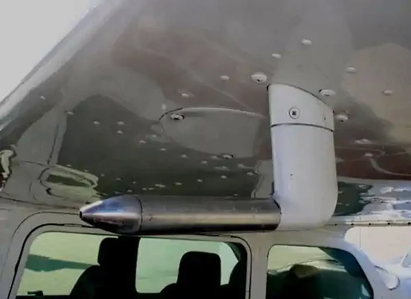
- The forward-facing opening admits dynamic pressure (ram/forced air) into the pitot tube.
- The device's placement is often on the front of the aircraft or an airfoil to capture smooth (undisturbed) air and reduce position errors. []
- A small drain hole on the back of the pitot tube allows moisture to escape, helping prevent water from collecting in the pitot system.
-
Pitot Heat:
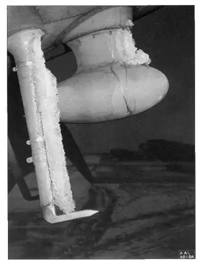
- Pitot Tubes are often electrically heated, which can prevent and remove ice accumulation. []
- Use pitot heat according to the Pilot's Operating Handbook/Airplane Flight Manual (POH/AFM), including any ground-operation limits.
- Unnecessary ground operation can overheat or damage some pitot heaters.
- When airborne, the airflow cools the device.
-
Static Port:
- Static ports sense ambient atmospheric pressure.
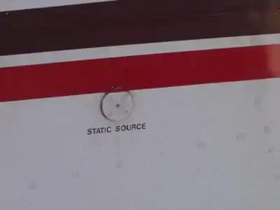
- Typically, ports are flush mounted on the side of the aircraft where air is undisturbed. []
- Some aircraft use heated static ports to prevent ice blockage.
- Static ports on opposite sides of the fuselage further reduce pressure (position) errors during slips and skids.
- The POH/AFM contains any corrections to the airspeed for the various flaps and landing gear configurations.
-
Alternate Static Source:
- An alternate static air source valve is available for abnormal situations on some aircraft.
- If the alternate source draws air from inside the cabin, where pressure is usually lower than outside, selecting it may produce the following indications:
- The altimeter reads higher than normal.
- Indicated airspeed (IAS) reads greater than normal.
- VSI momentarily shows a climb.
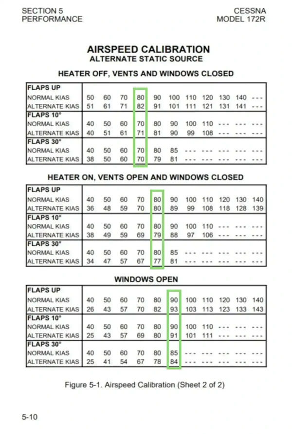
- Many POHs provide a correction table and aircraft-specific instructions for when operating with an alternate static source. []
- The altimeter's barometric setting does not correct errors caused by the alternate static source; use the POH/AFM corrections.
- An alternate static source may also affect connected altitude-reporting and flight-control equipment; check the aircraft-specific system description.
- Using alternate static sources can also decrease the accuracy beyond the 75 feet recommendation outlined in the Aeronautical Information Manual.



Airspeed Indicator Design and Function
- Airspeed indicators display an aircraft's indicated airspeed using mechanical or electronic sensing systems.
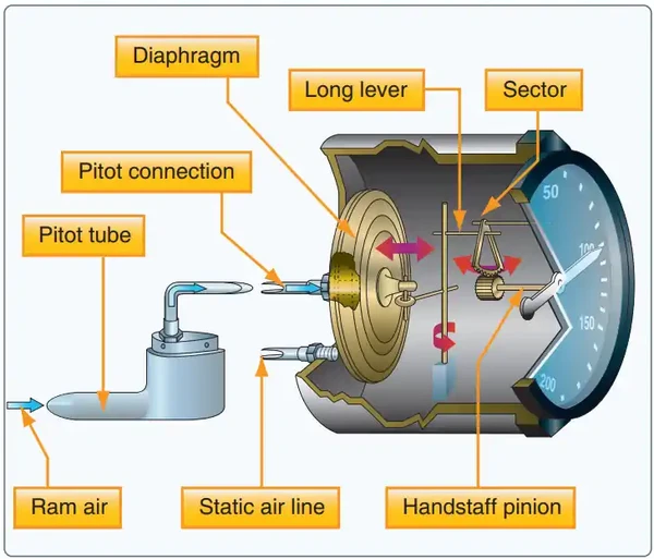
- Airspeed indicators compare dynamic pressure from the pitot tube (“ram/forced air”) with static pressure. []
- The pitot tube admits dynamic pressure, often called ram air/forced pressure.
- At low speeds, dynamic pressure is the difference between the pitot and static pressure inputs; compressibility becomes important at higher speeds.
- Pitot tubes are often electrically heated to prevent ice buildup from blocking the inlets.
- The static pressure enters through the static port(s) located on the side of the fuselage.
- The installation location most accurately detects prevailing atmospheric pressure (parallel to the air stream) and avoids dynamic (ram) air pressure, minimizing airflow-induced pressure errors.
- Some aircraft will have more than one port to measure pressure during slips and skids accurately.
- Some aircraft have an alternate static source for use if the primary source becomes blocked.
- Although less accurate, alternate static sources provide backup in an emergency, such as in instrument meteorological conditions (IMC).
- The pitot tube admits dynamic pressure, often called ram air/forced pressure.
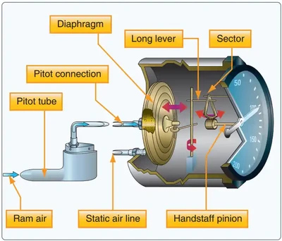
- A diaphragm compares the pitot and static pressure inputs to respond to dynamic pressure.
- The diaphragm expands when pitot pressure increases relative to static pressure.
- The diaphragm contracts when pitot pressure decreases relative to static pressure.
- The diaphragm's movement drives a pointer across the dial through a rocking shaft and gears. []
Airspeed Indications
- A conventional mechanical ASI uses a thin, corrugated diaphragm (aneroid) to measure the difference between pitot and static pressure (dynamic pressure).
- Numbers around the dial show indicated airspeed in the labeled units.
- Use the AFM/POH to identify the weight, configuration, and conditions associated with each marked speed.
- Performance speeds vary with aircraft weight, configuration, and atmospheric conditions.
- Airspeed is usually displayed in knots (kt), but some indicators use miles per hour (mph) or kilometers per hour (km/h).
- One knot equals one nautical mile per hour.
- One knot represents a higher speed than one mile per hour or one kilometer per hour.
- 1 kt ≈ 1.15 mph ≈ 1.85 km/h.
- The ASI displays indicated airspeed (IAS); use the aircraft's calibration data to obtain calibrated airspeed (CAS).
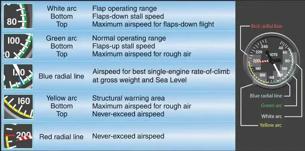
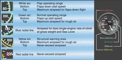
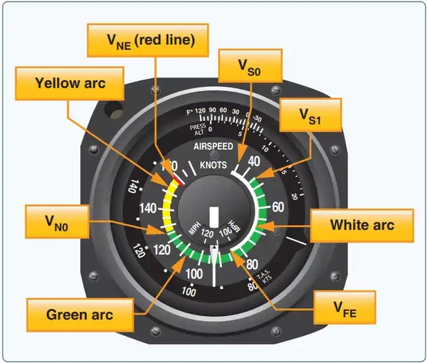
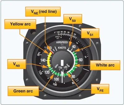
- Color-coded arcs and lines identify operating ranges and limits. []
- The white arc marks the flap operating range, from the landing-configuration stall speed (VS0) to the maximum flap-extended speed (VFE).
- The green arc marks the normal operating range, from VS1 to maximum structural cruising speed (VNO).
- Use the POH/AFM turbulence-penetration speed for rough air; VNO is not a universal rough-air target.
- The yellow arc is the caution range: operate here only in smooth air and with caution.
- The red line marks never-exceed speed (VNE).
- On light twins, the blue line marks the best single-engine rate-of-climb speed (VYSE).
Types of Airspeeds
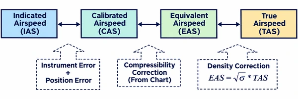
- Pilots reference many types of airspeeds for different purposes, such as performance or navigation planning. []
- Types of airspeeds include:
- Indicated Airspeed (IAS): the direct airspeed reading shown by an airspeed indicator.
- Calibrated Airspeed (CAS): indicated airspeed corrected for position and instrument errors.
- Equivalent Airspeed (EAS): calibrated airspeed corrected for compressibility effects.
- True Airspeed (TAS): the aircraft's speed relative to the surrounding air, obtained by correcting EAS for air density.
- Ground speed (GS): the actual speed of the airplane over the ground and is an important performance number for flight planning.
- Mach number: the ratio of the TAS of the aircraft to the speed of sound in the same atmospheric conditions.
Indicated Airspeed:
- Indicated Airspeed (IAS) is the direct airspeed reading shown by an airspeed indicator.
- The reading does not correct for atmospheric density variations, installation, or instrument errors.
- For a given true airspeed, indicated airspeed generally decreases as air density decreases.
- Manufacturers use this airspeed as the basis for determining aircraft performance.
- Published indicated V-speeds depend on the aircraft, weight, configuration, and operating conditions; use the AFM/POH values.
Calibrated Airspeed:
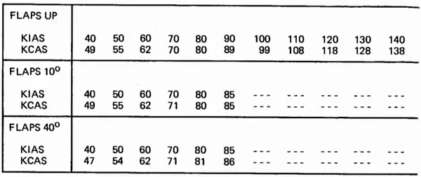
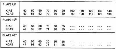
- Calibrated Airspeed (CAS) is the indicated airspeed of an aircraft, corrected for position and instrument error.
- Position error can vary with angle of attack (AOA), flap configuration, and airflow around the pressure sources.
- Errors can sometimes equal several knots and are generally greatest at low airspeeds.
- CAS is not generally the aircraft's true speed through the air.
- Manufacturers carefully choose the pitot-tube and static-port locations to minimize position error caused by disturbed airflow and local pressure changes around the aircraft.
- CAS equals TAS in standard sea-level conditions only.
- The POH/AFM has a chart or graph to correct IAS for these errors and provide the correct CAS for the various flap and landing gear configurations. []
- Aircraft with an alternate static source may have a separate airspeed-correction chart for its use.
Equivalent Airspeed:
- Equivalent airspeed (EAS) is calibrated airspeed corrected for compressibility effects.
- EAS represents aerodynamic loading by expressing the speed that would produce the same dynamic pressure at standard sea-level density.
- Compressibility corrections become more significant as Mach number increases (air molecules begin to stack up against the aircraft and instrumentation).
- Use the applicable flight-computer or aircraft data to convert CAS to EAS.
True Airspeed:
- True airspeed (TAS) is the aircraft's actual speed relative to the surrounding air.
- TAS is EAS corrected for air density; at low speeds, CAS can be corrected using pressure altitude and outside air temperature (OAT) when compressibility is negligible.
- The TAS is the speed used for planning and filing a flight plan.
- For a given EAS and pressure altitude, true airspeed increases as temperature increases.
- True airspeed increases with increased temperatures.
- True airspeed decreases as temperature decreases, for the same EAS and pressure altitude.
- For a given EAS, true airspeed increases as density altitude increases.
- True airspeed increases with increased density altitude.
- True airspeed decreases with decreased density altitude.
-
Calculating True Airspeed:
-
Flight Computer Method:
- The most accurate method is to use a flight computer.
- This method applies temperature and pressure corrections using the computer's airspeed correction scale.
- An electronic flight computer [Amazon] can also calculate true airspeed from calibrated airspeed, pressure altitude, and temperature.
- Just enter the CAS, pressure altitude, and temperature, and the computer calculates the TAS.
-
Rule of Thumb:
- A second method, a rule of thumb, provides the approximate TAS.
- For a rough estimate near standard atmospheric conditions, add 2 percent to CAS for each 1,000 feet of pressure altitude.
Formula:
- For example, at 5,000 feet pressure altitude: 5 × 0.02 = 0.10 (correction factor).
- 0.10 × 100 knots calibrated airspeed (KCAS) = 10 knots.
- 100 KCAS + 10 knots ≈ 110 knots true airspeed (KTAS).
-
Ground Speed:
- Ground speed (GS) is the actual speed of the airplane over the ground and is an important performance number for flight planning.
- Groundspeed is TAS adjusted for wind (airmass movement).
- GS decreases with a headwind and increases with a tailwind.
- An aircraft can have very low groundspeed despite substantial airspeed, such as when flying into a strong headwind.
- In level flight with no wind, groundspeed equals TAS; groundspeed and indicated airspeed are not interchangeable.
- Strong winds can make groundspeed and indicated airspeed differ significantly.
-
Calculating Groundspeed:
- For a direct headwind or tailwind in level flight, subtract the headwind from TAS or add the tailwind.
- For winds from other directions, use a flight computer or wind-triangle calculation to account for crosswind and heading correction.
- For a direct headwind or tailwind in level flight, subtract the headwind from TAS or add the tailwind.
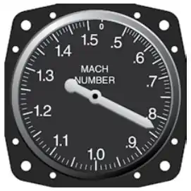
Mach Number:
- Mach number is the ratio of the TAS of the aircraft to the speed of sound in the same atmospheric conditions. []
- Some older mechanical Machmeters not driven from an air data computer use an altitude aneroid inside the instrument that converts pitot-static pressure into Mach number.
- Modern electronic Machmeters obtain Mach number from an air data computer using pitot and static pressure inputs.
Airspeed V-Speeds
- V-speeds are airspeeds of significance to the pilot during flight. []
- Use the aircraft's Pilot's Operating Handbook/Airplane Flight Manual (POH/AFM) for applicable V-speeds and operating limitations.
- The following list defines the applicable V-speeds.
- These do not apply to every aircraft you fly.
- Use the following definitions to interpret the V-speeds in your aircraft's POH/AFM.
- The white band indicates the VS0 to VFE range.
- The green band indicates the VS1 - VNO range.
- The yellow band indicates the VNO - VNE range.
-
Maximum Allowable Airspeed:
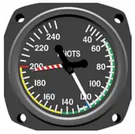
- An aneroid or altimeter mechanism actuates the maximum airspeed pointer that moves it to a lower value as air density decreases. []
- This instrument looks much like a standard air-speed indicator, calibrated in knots, but has an additional pointer colored red, checkered, or striped.
- Some aircraft use true ASIs with temperature-compensated aneroid bellows inside the instrument case.
- These bellows modify the movement of the rocking shaft inside the instrument case so the pointer shows the actual TAS.
- Other true-airspeed indicators use a manually adjustable sub-dial visible through openings in the main dial.
- A knob on the instrument allows the pilot to rotate the sub-dial and align an indication of the outside air temperature with the pressure altitude flown.
- This alignment causes the instrument pointer to indicate the TAS on the sub-dial.
-
Maneuvering Speed:
- Design maneuvering speed, VA, decreases as aircraft weight decreases.
- VA concerns a single full-control input in one axis in smooth air; it is not protection against every possible control input or gust.
- Avoid repeated, reversing, or simultaneous full-control inputs, even below VA.
- Use the VA published or calculated according to the POH/AFM for the actual weight. []
- American Airlines Flight 587 illustrates that repeated rudder reversals can cause structural failure even below VA.
- Formula:
- Design maneuvering speed, VA, decreases as aircraft weight decreases.
- Some important speeds, including VA and VLE, may not be marked on the ASI; refer to the POH/AFM and placards.


Airspeed Indicator Preflight Actions
- Before takeoff, the ASI should read zero unless a strong wind blowing into the pitot tube produces an indication.
- During the takeoff roll, verify that airspeed increases at an appropriate rate.
- Use the callout "airspeed alive" when required by your checklist or operating procedures.
Inertial Reference Unit (IRU), Inertial Navigation System (INS), and Attitude Heading Reference System (AHRS)
- Glass flight decks may integrate IRU, INS, and AHRS information with air-data inputs; consult the installed system's documentation to identify the source of each indication.
- An electronic attitude display commonly receives information from an Attitude and Heading Reference System (AHRS); other installations may use an Inertial Reference Unit (IRU) or Inertial Navigation System (INS).
- IRUs are self-contained systems comprised of gyros and accelerometers that provide aircraft attitude (pitch, roll, and heading), position, and velocity information in response to signals resulting from inertial effects on system components.
- Once aligned with a known position, IRUs continuously calculate position and velocity. IRU position accuracy decays with time.
- This degradation is known as "drift."
- INSs combine the components of an IRU with an internal navigation computer.
- By programming a series of waypoints, these systems will navigate along a predetermined track.
- AHRSs are electronic devices that provide attitude information to aircraft systems such as weather radar and autopilot, but do not directly compute position information.
- Aircraft equipped with slaved compass systems may be susceptible to heading errors caused by exposure to magnetic field disturbances (flux fields) found in materials that are commonly located on the surface or buried under taxiways and ramps.
- These materials generate a magnetic flux field that can be sensed by the aircraft's compass system flux detector or "gate", which can cause the aircraft's system to align with the material's magnetic field rather than the earth's natural magnetic field.
- The system's erroneous heading may not self-correct.
- Before takeoff, check for heading misalignment that may have developed during taxi.
- Correct any heading misalignment using the manufacturer's or other applicable procedures before takeoff.
Operating Considerations:
- Aircraft may have one or more AHRS units, depending on the installed avionics configuration.
- Verify the installed configuration using the aircraft's Pilot's Operating Handbook/Airplane Flight Manual, applicable avionics supplements, and equipment list.
- Consult the applicable avionics pilot's guide to identify sensor-selection controls and source annunciations, such as AHRS 1 and AHRS 2, when provided.
- Two displays do not necessarily mean two independent AHRS sources; both displays may receive information from the same unit.
- Know which source supplies each display and follow the aircraft-specific procedures for a failed or disagreeing source.
- Complete initialization and alignment before relying on the indications, following the installed equipment's procedures.
- Do not assume every system permits the same aircraft movement or in-flight realignment conditions.
- The following failure examples apply to the legacy Cessna Nav III G1000 with GRS 77 AHRS shown above.
- Other installations and software versions may behave differently.
- Magnetometer failure can invalidate heading while attitude remains available.
- In this G1000 installation, the primary flight display (PFD) marks the invalid heading with a red X.
- Loss of GPS does not necessarily mean loss of attitude and heading.
- If one Global Positioning System (GPS) input fails, the AHRS uses the remaining input and issues an alert.
- If both GPS inputs fail, attitude and heading remain available while magnetometer and airspeed inputs remain valid.
- Loss of airspeed data together with GPS can invalidate both attitude and heading.
- Read advisory messages and identify which indications are invalid.
- Use the aircraft's abnormal procedures and available independent standby instruments rather than relying on red-X indications.
- Aircraft may have one or more AHRS units, depending on the installed avionics configuration.
Airspeed Indicator Anomalies and Malfunctions
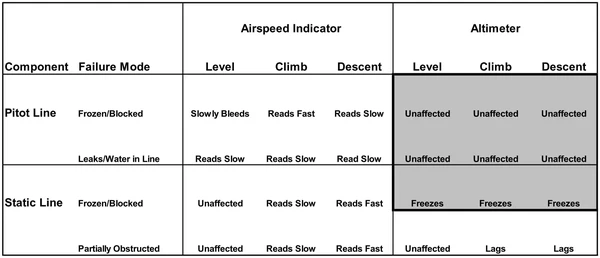
- Pitot-static instruments are generally reliable, but cross-check their indications for consistency. []
- A failure may develop gradually and become difficult to recognize without a consistent cross-check.
- Common pitot-static system problems include:
- Icing over the Pitot or static ports. []
- Water trapped in the lines, including water introduced during washing or maintenance.
- Compromise of system integrity:
- Leaks due to holes or loose fittings.
- Kinks in the lines.
- Obstructions/blockages.
- Taped or covered ports.
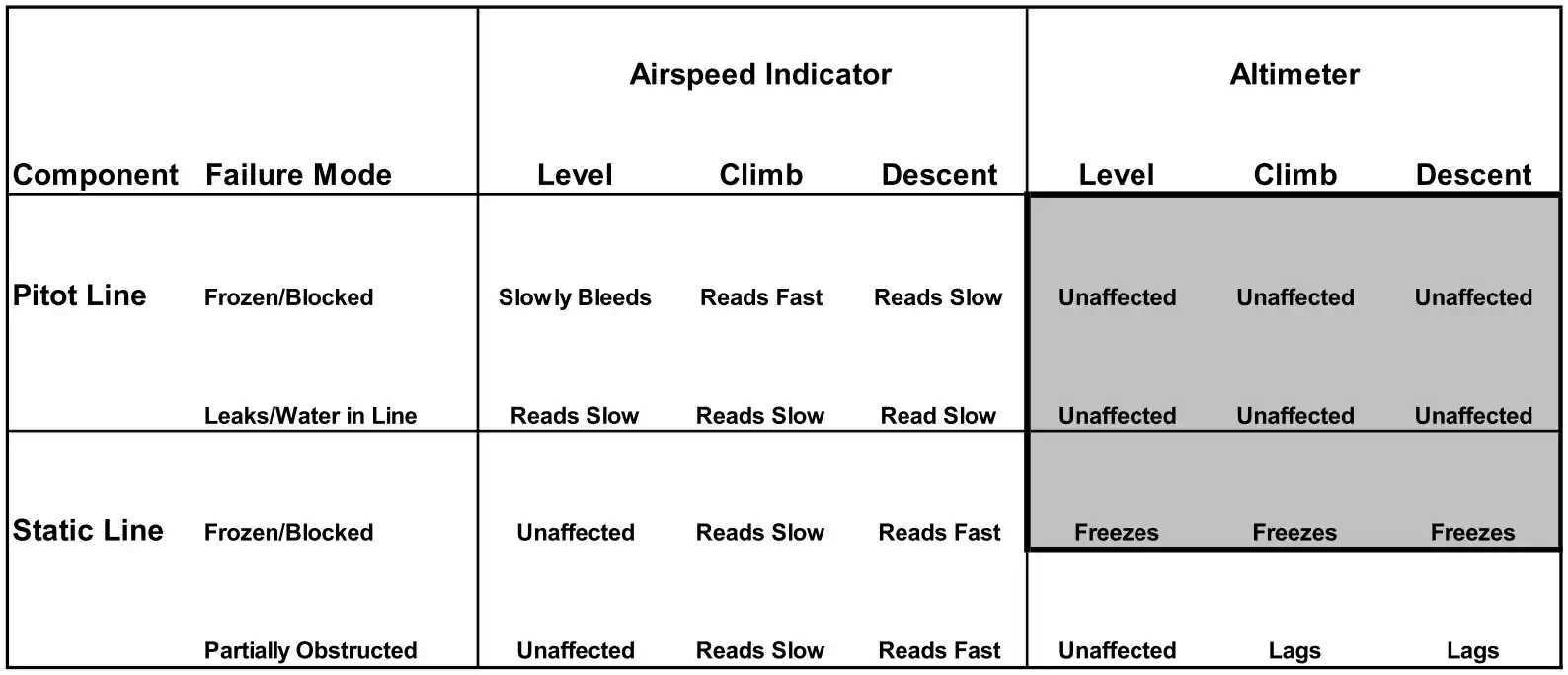
- Blockage effects depend on which openings are obstructed.
- If the pitot inlet is blocked but its drain remains open, with the static source clear, indicated airspeed falls toward zero.
- During preflight, remove the pitot cover and inspect the pitot inlet, drain hole, and static ports for obstructions.
- Blockages may result from FOD, striking an object (damaging instruments), insects, trapped moisture, loss of system integrity, icing, etc.
- Static-source position error varies with airspeed, angle of attack, and aircraft configuration; generally highest at low airspeed, high angle of attack, and in a dirty configuration.
- Position error may increase in certain aircraft configurations.
- Treat an airspeed indication that conflicts with known pitch, power, configuration, altitude, or groundspeed cues as unreliable until the discrepancy is resolved.
- Maintain aircraft control using the airplane manufacturer's unreliable-airspeed or instrument-malfunction procedure, including the prescribed pitch-and-power settings.
- Cross-check independent instruments and available groundspeed information, but do not substitute GPS (Global Positioning System) groundspeed directly for indicated airspeed.
- If icing may be obstructing the pitot system, use pitot heat in accordance with the AFM/POH and leave icing conditions as soon as practical.
-
Pitot-Tube and Drain Hole Blockage (static open):
- The airspeed indicator will freeze and read like an altimeter as the trapped pitot pressure now remains constant, and the static pressure changes with climbs and descents.
- The measure of ram air to static air means that as altitude increases and pressure decreases, the instrument will read artificially high compared to the same dynamic (ram) pressure.
- Likewise, if pressure increases, such as in a descent, it will read artificially low.
- At the altitude where the blockage occurred, the indicator shows the value present when the blockage occurred; that reading is not necessarily correct if actual airspeed changes.
-
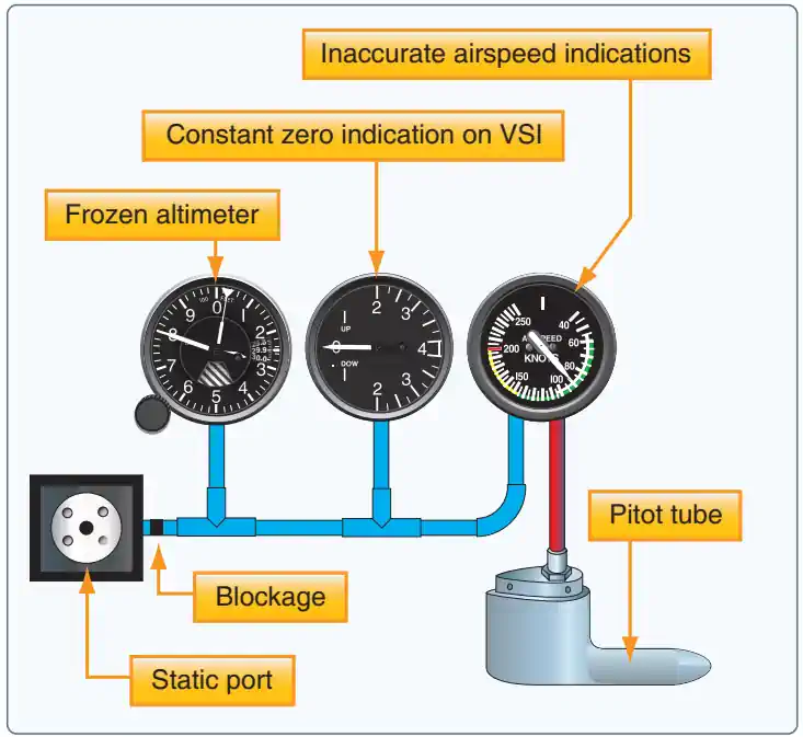
Static Blockage:
- If the static system becomes blocked but the pitot tube remains clear, the ASI continues to operate; however, it is inaccurate.
- At the altitude where the blockage occurs, airspeed indications would be normal.
- The airspeed indicates lower than the actual airspeed when the aircraft is operated above the altitude where the static ports became blocked because the trapped static pressure is higher than normal for that altitude.
- When operating at a lower altitude, a faster than actual airspeed is displayed due to the relatively low static pressure trapped in the system.
- If the aircraft descends, the static pressure increases on the pitot side showing an increase on the ASI. This assumes that the aircraft does not actually increase its speed.
- The increase in static pressure on the pitot side is equivalent to an increase in dynamic pressure since the pressure cannot change on the static side.
- If an aircraft begins to climb after a static port becomes blocked, the airspeed begins to show a decrease as the aircraft continues to climb.
- During a climb with the static source blocked, pressure in the instrument case remains fixed while pressure at the pitot inlet decreases, reducing the indicated pressure differential and causing the airspeed indication to decrease.
- Some aircraft are equipped with an alternate static source in the flight deck.
- In the case of a blocked static source, opening the alternate static source introduces static pressure from the flight deck into the system.
- Flight-deck static pressure is usually lower than outside static pressure.
- Check the aircraft AFM/POH for airspeed corrections when utilizing alternate static pressure.
- A blockage of the static system also affects the altimeter and VSI, as well.
- Airspeed indicator failure demonstrates the importance of relating pitch attitudes to airspeeds.
- GPS groundspeed can support the cross-check, but it measures speed over the ground, not indicated airspeed.
- Slips can introduce position error in the airspeed indication.
Tap a green circle to add a blockage; tap a red X to remove it.
All openings clear.
Blue: static pressure · Red: pitot pressure · Green circle: clear · Red X: blocked.
What is blocking this opening?
Airspeed indicator
Altimeter
Vertical speed indicator
±600 ft/min; demonstration time runs 10× faster.
Instrument readings and explanations
Airspeed indicator
Altimeter
Vertical speed indicator
Based on the Cessna Model 172 maintenance manual, 34-11-00, Figure 201, Sheet 1 (3 July 2006): airplanes without Garmin G1000.
Common Training Aircraft Pitot-Static System Characteristics
-
Piper Arrow:
- Composed of a heated Pitot tube on the lower left wing.
- Two static ports are located on each side of the fuselage.
- If installed, the alternate static source supplies cabin pressure; verify its location and operating instructions in the POH/AFM.
-
Cessna 172:
- A pitot tube is mounted below the left wing; heating equipment depends on model and installation.
- Many Cessna 172 models use a static port on the left side of the forward fuselage.
- When installed, pitot heat includes a heating element, electrical control, circuit protection, and wiring; ratings vary by model.
- If installed, the alternate static source supplies cabin pressure; check the aircraft-specific control location and corrections.
Airspeed Indicator Lessons & Case Studies
- National Transportation Safety Board (NTSB) Identification: CEN20LA069:
- The NTSB determines the probable cause(s) of this accident to be: Water trapped in the static system, which resulted in incorrect airspeed display information and the pilot's forced landing.
- National Transportation Safety Board Identification: CEN14LA243:
- The NTSB determines the probable cause(s) of this accident to be: The pilot’s failure to maintain adequate airspeed and his exceedance of the airplane’s critical angle-of-attack while maneuvering at low altitude, which led to an aerodynamic stall and loss of control. Contributing to the accident was the installation of an inappropriate airspeed indicator that did not provide airspeed indications near the airplane’s stall speed.
- National Transportation Safety Board Identification: CEN10CA341:
- The NTSB determines the probable cause(s) of this accident to be: The pilot's failure to lower the landing gear. Contributing to the accident was the pilot's distraction with an erroneous airspeed indicator.
- National Transportation Safety Board Identification: DCA09IA064:
- The NTSB determines the probable cause(s) of this incident to be: Brief and temporary blockage of the pitot probes in cruise flight, most likely due to ice crystals aloft, leading to erroneous airspeed indications and airplane automation degradation as designed. Contributing to the incidents were design features of the Thales AA probes which left them more susceptible to high altitude ice crystal icing than other approved pitot probe designs.
- National Transportation Safety Board Identification: CEN26LA232:
- The NTSB determines the probable cause(s) of this accident to be: A partial blockage of the pitot static system that precluded the airspeed indicator from displaying the correct airspeed which led to the faster landing speed and bounced landing.
- National Transportation Safety Board Identification: WPR22LA233:
- The NTSB determines the probable cause(s) of this accident to be: The pilot’s failure to maintain directional control during a landing attempt, which resulted in a ground loop and collision with terrain. Contributing to the accident was the absence of an airspeed indicator due to an alternator failure.
- National Transportation Safety Board Identification: ANC21LA077:
- The NTSB determines the probable cause(s) of this accident to be: The pilot’s loss of control on go-around in gusting crosswind conditions. Contributing to accident was the pilot’s decision to attempt to land at a short off-airport landing site with a malfunctioning airspeed indicator.
- National Transportation Safety Board Identification: ERA19LA269:
- The NTSB determines the probable cause(s) of this accident to be: A blockage of the pitot static system that preclude the airspeed indicator from displaying speeds greater than 40 mph, which led the pilot to abort the landing and overrun the runway.
- National Transportation Safety Board Identification: CEN19FA100:
- The NTSB determines the probable cause(s) of this accident to be: A loss of airspeed indication due to icing of the airplane's pitot probe, and the pilot's loss of control while maneuvering.
- National Transportation Safety Board Identification: ERA19LA031:
- The NTSB determines the probable cause(s) of this accident to be: A leak in the pitot-static system for reasons that could not be determined based on the available information, which resulted in an airspeed indication error, an aborted takeoff, and a subsequent runway overrun.
Airspeed Indicator Knowledge Check
Choose the knowledge check that matches your current training for Airspeed Indicator.

PPL knowledge check
Core Knowledge Review
Review foundational knowledge, key concepts, and practical considerations. Topic: Airspeed Indicator.
- Immediate feedback
- Answer explanations
- Account progress tracking
Sport knowledge check
Sport Pilot Knowledge
Review the foundational knowledge and decisions used in sport-pilot operations. Topic: Airspeed Indicator.
- Immediate feedback
- Answer explanations
- Account progress tracking

CPL knowledge check
Advanced Application
Apply knowledge to advanced operations, risk management, and aeronautical decision-making. Topic: Airspeed Indicator.
- Immediate feedback
- Answer explanations
- Account progress tracking

Instrument knowledge check
Instrument Knowledge
Practice the procedures, systems, weather, and decisions used in instrument flight. Topic: Airspeed Indicator.
- Immediate feedback
- Answer explanations
- Account progress tracking

CFI knowledge check
Instructor Knowledge
Review the technical knowledge expected of an airplane flight instructor. Topic: Airspeed Indicator.
- Immediate feedback
- Answer explanations
- Account progress tracking

CFII knowledge check
Instrument Instructor Knowledge
Review instrument knowledge at the depth expected of an instrument flight instructor. Topic: Airspeed Indicator.
- Immediate feedback
- Answer explanations
- Account progress tracking
Why Take a Quiz?
Quizzes reinforce key concepts, identify knowledge gaps, and build confidence for real-world decisions. Quiz material is representative of the information provided here and is not based on or sourced from the Federal Aviation Administration test bank.
Airspeed Indicator Interactive Scenario
The Airspeed That Froze in the Climb
Manage a pitot-static problem from preflight through a no-airspeed landing as changing indications reveal how blockage, altitude, configuration, and cross-checks interact. Abbreviations used in this scenario: revolutions per minute (RPM).
Scenario Complete
Airspeed Indicator Conclusion
- The airspeed indicator measures a pressure difference between the pitot and static systems, rather than speed over the ground.
- A fault in either pressure source can therefore make the indication unreliable.
- Indicated, calibrated, equivalent, and true airspeed are different quantities.
- Use the speed definition specified by the aircraft procedure or performance chart rather than treating them as interchangeable.
- Color arcs and V-speeds must be interpreted for the aircraft being flown.
- Account for the applicable configuration, weight, and operating conditions when selecting an operating speed.
- Recognize blockage patterns and cross-check unexpected indications.
- The result depends on whether the pitot inlet, drain, static source, or connecting line is obstructed.
- Pitot heat addresses pitot icing; it does not clear every possible obstruction or restore a blocked static system.
- Use the aircraft-specific unreliable-airspeed or alternate-static procedure when required.
- Use the airspeed indicator to monitor operating speeds and avoid exceeding aircraft limitations.
- Exceeding those limits may cause over-stress and damage to the aircraft.
- Always keep in mind the effects of parallax error.
- Use speed in knots to estimate distance traveled per minute.
- 60 knots groundspeed equals 1 nautical mile per minute over the ground; 60 KTAS describes motion through the air.
- Airspeed indicator readings are all relative to the surrounding airmass.
- Note that while an approach or landing speed may be specified, the speeds held on approach will differ from final to round-out to flare.
- Consult the Pilot's Operating Handbook/Airplane Flight Manual (POH/AFM) for airspeed calibration, alternate-static corrections, and aircraft-specific limitations.
Airspeed Indicator References
- Cessna Model 172 Maintenance Manual, 34-11-00, Figure 201, Sheet 1: Pitot/Static System Schematic (airplanes without Garmin G1000).
- Federal Aviation Administration - Pilot/Controller Glossary.
- Aeronautical Information Manual (1-1-15) Inertial Reference Unit (IRU), Inertial Navigation System (INS), and Attitude Heading Reference System (AHRS).
- Bold Method - What's The Difference Between Approach Speed And Threshold Crossing Speed?.
- CFI Notebook.net - Performance Calculations.
- CFI Notebook.net - Pitot Static System.
- Federal Aviation Regulations (91.205) Powered civil aircraft with standard category U.S. airworthiness certificates: Instrument and equipment requirements.
- Federal Aviation Regulations (91.411) Altimeter system and altitude reporting equipment tests and inspections.
- Instrument Flying Handbook (3-8) Airspeed Indicator (ASI).
- National Aeronautics and Space Administration (NASA) - Pitot-Static Tube.
- Smart Cockpit.com - Getting to Grips with Aircraft Performance.