Instrument Approach Procedures
Instrument approaches establish methodical transitions from the en-route environment to terminal environment in instrument meteorological conditions.
Introduction to Instrument Approach Procedures
- Instrument Approach Procedures, or IAPs for short, are established to provide the transition from the en-route structure to the terminal environment when operating under Instrument Flight Rules (IFR), and/or during Instrument Meteorological Conditions (IMC), to a point where a safe landing can be made.
- Broken up primarily into initial, intermediate, final (includes a visual segment), and missed approach segments, instrument approaches create a "road" maps for the sky for the terminal area.
- The U.S. Government distributes charts produced by National Geospatial-Intelligence Agency (NGA) and FAA.
- Once approved, instrument approach procedures are published and distributed by the government and commercial cartographers as instrument approach charts.
- Nearing the terminal environment, the pilot conducts an approach briefing to familiarize the pilot and/or crew on the maneuvers and procedures required to safely complete the approach.
- RNP/AR Instrument Approach Procedures.
- Minimum Vectoring Altitudes..
- Instrument Approach Segments.
- Area Navigation (RNAV) Instrument Approach Charts.
- Procedure Turn and Hold-in-lieu of Procedure Turn.
- Timed Approaches from Holding.
- Special Instrument Approach Procedures.
- Visual Approaches.
- Side-Step Maneuver.
- Low approaches are low passes, essentially a go-around maneuver following an approach, expediting a particular operation (such as training.
- Low approaches may due to training, were pilots are conducting Practice instrument approaches.
- Charted Visual Flight Procedures.
- Related to pilot proficiency, pilots may be given an option approach clearance which means the pilot can conduct a low approach, perform a touch and go, or land to a full stop.
- Many approaches provide pilots with the option to circling to landing, enabling pilots to fly the most appropriate approach for their circumstances, but still land on the desired runway if different from the approach flown.
- GPS Instrument Approaches.
- While many approaches require some sort of airborne receiver, radar approaches utilize ground-based air traffic control equipment to provide pilots with lateral and in some cases vertical approach guidance to an airport.
- Regardless of the type of approach flown, pilots must be aware and consider the approach and landing minimums to set expectations for "breaking out" below the weather as well as overall regulatory requirements to maintain obstacle clearance.
- When pilots fail to find the runway environment or do so in a safe position to make a landing, pilots will execute a missed approach.
- Direction Finding Instrument Approaches.
- Contact Approaches.
- Simultaneous Approaches.
- High-Altitude Penetration Approaches.
- Instrument Approach Responsibilities.
- Communications Release of IFR Aircraft Landing at an Airport Without an Operating Control Tower.
- Advance Information on Instrument Approaches.
- IFR Approaches/Ground Vehicle Operations.
- Instrument Approach Procedures-Related Airman Certification Standards.
Instrument Approach Procedures Key Highlights
- Instrument approach procedures provide standardized navigation guidance for safely transitioning from instrument flight to landing.
- Approach procedures may use ground-based navigation aids, RNAV systems, or satellite-based navigation guidance.
- Instrument approaches include segments such as initial, intermediate, final, and missed approach phases.
- Pilots must comply with published altitudes, courses, minimums, and approach procedures to maintain obstacle clearance and safe operations.
- Precision approaches provide both lateral and vertical guidance, while nonprecision approaches provide lateral guidance only.
- Approach briefings improve situational awareness by reviewing frequencies, courses, minimums, missed approach procedures, and airport information.
- Weather conditions, aircraft performance, and workload management significantly affect instrument approach operations.
- Missed approach procedures provide standardized escape paths when landing conditions are unsafe or visual references are inadequate.
- Modern avionics systems improve situational awareness but require proper automation management and system understanding.
- Understanding instrument approach procedures improves instrument proficiency, aeronautical decision-making, and overall flight safety.
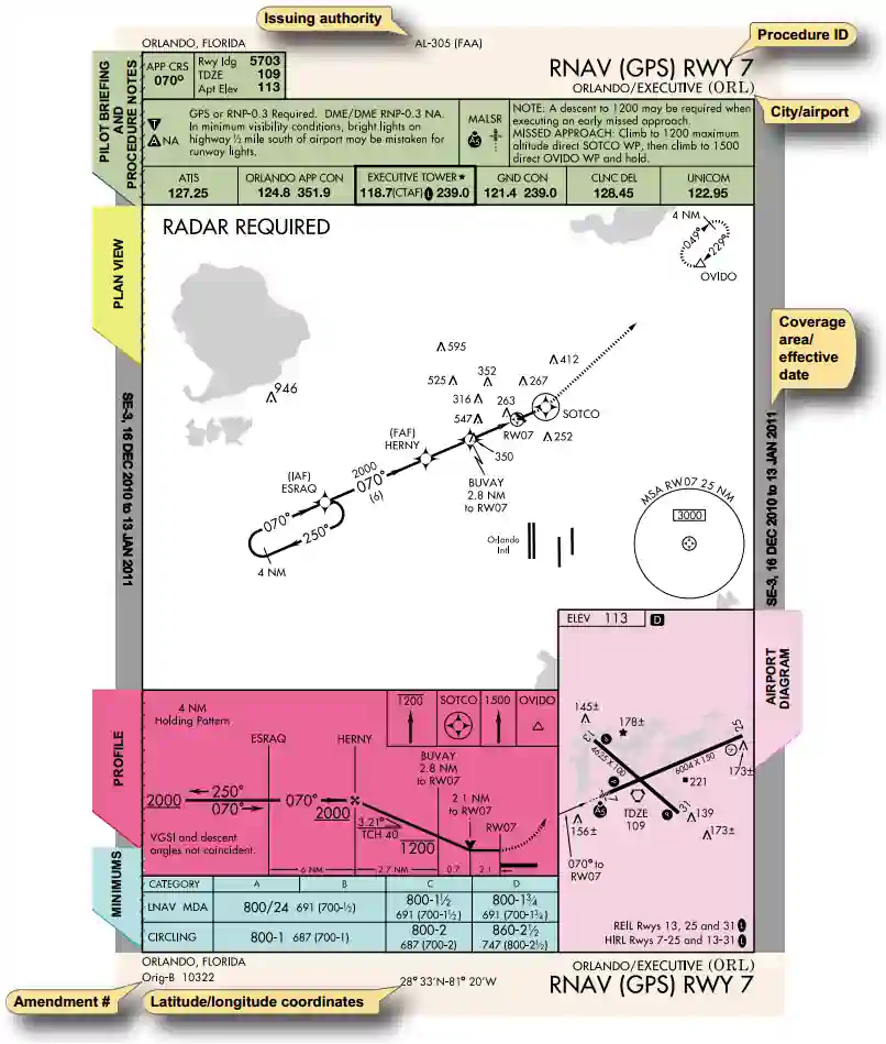
Instrument Approach Charts
- The instrument approach chart is the formal presentation of the IAP.
- Charts consist of five principal sections: []
-
Pilot Briefing and Procedure Notes Section:
- The pilot briefing and procedure notes are the starting place for any approach to be flown, and are directly related to the conduct of the approach brief.
-
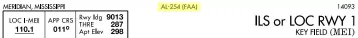
Instrument Approach Chart Issuing Authority:
- The issuing authority is labeled at the top center of the approach plate:
- Civil procedures are defined with "FAA" in parenthesis; e.g., (FAA). []
- DOD procedures are defined using the abbreviation of the applicable military service in parenthesis; e.g., (USAF), (USN), (USA). []
- If there are military procedures published at a civil airport, aircraft operating under 14 CFR Part 91 must use the civil procedure(s).
- 14 CFR Section 91.175(g), Military airports, requires civil pilots flying into or out of military airports to comply with the IAPs and takeoff and landing minimums prescribed by the authority having jurisdiction at those airports.
- Unless an emergency exists, civil aircraft operating at military airports normally require prior authorization, commonly referred to as "Prior Permission Required" or "PPR."
- Information on obtaining a PPR for a particular military airport can be found in the Chart Supplement U.S. []
- Civil aircraft may conduct practice VFR approaches using DOD instrument approach procedures when approved by the air traffic controller
- The issuing authority is labeled at the top center of the approach plate:
-
Navigation Equipment Requirements:
- The navigation equipment required to join and fly an instrument approach procedure is indicated by the title of the procedure and notes on the chart
- Straight-in IAPs are identified by the navigational system providing the final approach guidance (i.e., VOR) and the runway to which the approach is aligned (i.e., 16) []
- Circling only approaches are identified by the navigational system providing final approach guidance (i.e. VOR) and a letter (i.e. A) []
- More than one navigational system separated by a slash indicates that more than one type of equipment must be used to execute the final approach []
- More than one navigational system separated by the word "or" indicates either type of equipment may be used to execute the final approach []
- Pilots should review the procedure's notes, planview annotations, and PBN/equipment requirements boxes to determine the capability needed to accomplish the procedure.
- The name of an instrument approach, as published, is used to identify the approach.
- The controller will use the name of the approach as published, but must advise the aircraft at the time an approach clearance is issued that the inoperative or unreliable approach aid component is unusable, except when the title of the published approach procedures otherwise allows, for example, "ILS or LOC."
- Except when being radar vectored to the final approach course, when cleared for a specifically prescribed IAP; i.e., "cleared ILS runway one niner approach" or when "cleared approach," i.e., execution of any procedure prescribed for the airport, pilots must execute the entire procedure commencing at an IAF or an associated feeder route as described on the IAP chart unless an appropriate new or revised ATC clearance is received, or the IFR flight plan is canceled.
- Pilots planning flights to locations which are private airfields or which have instrument approach procedures based on private navigation aids should obtain approval from the owner.
- In addition, the pilot must be authorized by the FAA to fly special instrument approach procedures associated with private navigation aids.
- Private owners are responsible for the NAVAID's usability.
- Air traffic controllers are not required to question pilots to determine if they have permission to land at a private airfield or to use procedures based on privately owned navigation aids, and they may not know the status of the navigation aid.
- Controllers presume a pilot has obtained approval from the owner and the FAA for use of special instrument approach procedures and is aware of any details of the procedure if an IFR flight plan was filed to that airport.
- Pilots should not rely on radar to identify a fix unless the fix is indicated as "RADAR" on the IAP. Pilots may request radar identification of an OM, but the controller may not be able to provide the service due either to workload or not having the fix on the video map
- The navigation equipment required to join and fly an instrument approach procedure is indicated by the title of the procedure and notes on the chart
-
Pilot Briefing Contents:
- Thematic approach numbers are provided, including the final approach course, runway landing distance, touchdown zone elevation and airport elevation.
- Additionally, frequencies in the order pilots would expect to use them are provided.
- The tower frequency box is always bolded.
-
Procedure Notes:
-
Alternate Considerations:
- If the aircraft is a valid alternate, an "A"
- However, even with an "A," the notes may stipulate the approach not being available at night (as defined as FAR 1.1).
- If the approach is not a valid alternate, it will be labeled "A NA."
- This usually means the approach cannot be guaranteed and, therefore, cannot be relied upon as an alternate.
- If the aircraft is a valid alternate, an "A"
-
Approach Lighting:
- Approach lighting for the primary runway serviced is listed.
-
Published Temperature Limitations:
- There are currently two temperature limitations that may be published in the notes box of the middle briefing strip on an instrument approach procedure (IAP):
- A temperature range limitation associated with the use of baro-VNAV that may be published on a United States PBN IAP titled RNAV (GPS) or RNAV (RNP); and/or
- A Cold Temperature Airport (CTA) limitation designated by a snowflake ICON and temperature in Celsius (C) that is published on every IAP for the airfield
- There are currently two temperature limitations that may be published in the notes box of the middle briefing strip on an instrument approach procedure (IAP):
-
-
Plan View:
- The plan view gives a bird's-eye view of the path the pilot is to fly according to the procedure.
- In some cases, other types of navigation systems, including radar, may be required to execute different portions of the approach or to navigate to the IAF (e.g., an NDB procedure turn to an ILS, an NDB in the missed approach, or radar required to join the procedure or identify a fix).
- When the procedure requires radar or other equipment for entry from the en-route environment, the plan view of the approach chart will include a note such as RADAR REQUIRED or ADF REQUIRED.
- When the procedure requires radar or other equipment for portions outside the final approach segment—including the missed approach—the notes box in the pilot briefing section of the approach chart will include a note such as RADAR REQUIRED or DME REQUIRED.
- Notes are not charted when VOR is required outside the final approach segment.
- Pilots should ensure the aircraft is equipped with the required NAVAID(s) to execute the approach, including the missed approach.
- Some military (i.e., U.S. Air Force and U.S. Navy) IAPs have these "additional equipment required" notes charted only in the plan view of the approach procedure and do not conform to the same application standards used by the FAA.
- The Cat II and Cat III designations differentiate between multiple ILSs to the same runway, unless there are multiple of the same type.
- The FAA has initiated a program to provide a new notation for LOC approaches when charted on an ILS approach requiring other navigational aids to fly the final approach course.
- The LOC minimums will be annotated with the NAVAID required (e.g., "DME Required" or "RADAR Required").
- During the transition period, ILS approaches will still exist without the annotation.
- Many ILS approaches having minima based on RVR are eligible for a landing minimum of RVR 1800. Some of these approaches are to runways that have touchdown zones and centerline lights. For many runways without touchdown and centerline lights, it is still possible to allow a landing with a minimum RVR of 1800. For these runways, the normal ILS minimum of RVR 2400 can be annotated with a single or double asterisk or the dagger symbol "†"; for example, "** 696/24 200 (200/1/2)." A note is included on the chart stating "**RVR 1800 authorized with use of FD or AP or HUD to DA." The pilot must use the flight director, or an autopilot with an approved approach coupler, or a heads-up display to the decision altitude or to the initiation of a missed approach. In the interest of safety, single-pilot operators should not fly approaches to 1800 RVR minimums on runways without touchdown and centerline lights using only a flight director, unless accompanied by an autopilot with an approach coupler.
- The naming of multiple approaches of the same type to the same runway is also changing. Multiple approaches with the same guidance will be annotated with an alphabetical suffix beginning at the end of the alphabet and working backwards for subsequent procedures (e.g., ILS Z RWY 28, ILS Y RWY 28, etc.). The existing annotations such as ILS 2 RWY 28 or Silver ILS RWY 28 will be phased out and replaced with the new designation. The Cat II and Cat III designations are used to differentiate between multiple ILSs to the same runway, unless there are multiples of the same type.
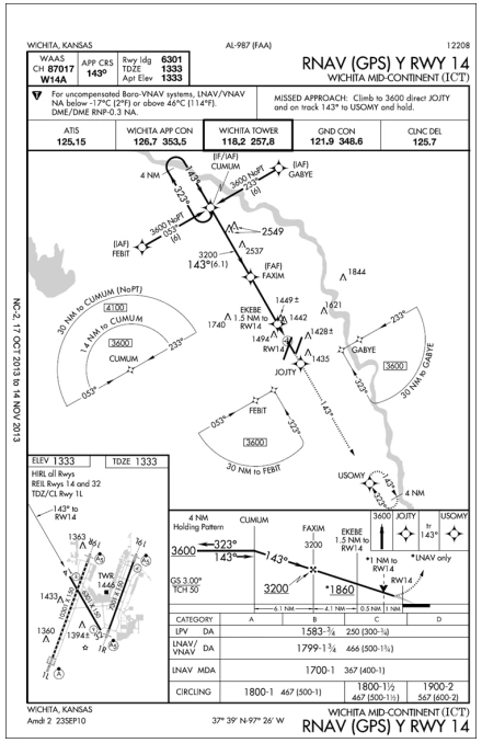
- RNAV (GPS) approaches to LNAV, LP, LNAV/VNAV, and LPV lines of minima using WAAS and RNAV (GPS) approaches to LNAV and LNAV/VNAV lines of minima using GPS are charted as RNAV (GPS) RWY (Number) (e.g., RNAV (GPS) RWY 21).
- Performance-Based Navigation (PBN) Box. As charts are updated, a procedure's PBN requirements and conventional equipment requirements will be prominently displayed in separate, standardized notes boxes. For procedures with PBN elements, the PBN box will contain the procedure's navigation specification(s) and, if required, specific sensors or infrastructure for the navigation solution, any additional or advanced functional requirements, the minimum Required Navigation Performance (RNP) value, and any amplifying remarks. Items listed in this PBN box are REQUIRED for the procedure's PBN elements. For example, an ILS with an RNAV missed approach would require a specific capability to fly the missed approach portion of the procedure. That required capability will be listed in the PBN box. The separate Equipment Requirements box will list ground-based equipment requirements. On procedures with both PBN elements and equipment requirements, the PBN requirements box will be listed first. The publication of these notes will continue incrementally until all charts have been amended to comply with the new standard.
-
Minimum Safe Altitude:
-
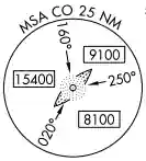
Minimum Safe Altitude - The FAA publishes Minimum Safe/Sector Altitudes (MSAs) on IAP charts and Departure Procedure (DPs) graphic charts for emergency use.
- MSAs provide 1,000 feet of clearance over all obstacles but do not necessarily ensure acceptable navigation signal coverage (as with OROCAs).
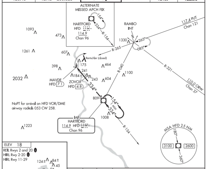
- The MSA depiction on the plan view of an approach chart or on a DP graphic chart includes the identifier of the MSA center point, the applicable MSA radius, a depiction of the sector(s), and the minimum altitudes above mean sea level that provide obstacle clearance. []
- For conventional navigation systems, the MSA is normally based on the primary omnidirectional facility on which the IAP or DP graphic chart is predicated, but may be based on the airport reference point (ARP) if no suitable facility is available.
- For RNAV approaches or DP graphic charts, the MSA is based on an RNAV waypoint.
- MSAs normally have a 25 NM radius; however, for conventional navigation systems, this radius may be expanded to 30 NM if necessary to encompass the airport landing surfaces.
- A single-sector altitude is normally established; however, when the MSA is based on a facility, and it is necessary to obtain relief from obstacles, an MSA with up to four sectors may be established.
-
-
Profile View:
- The profile view provides pilots with the approach procedure, the sequential missed approach procedure, and the approach minimums.
-
Profile View Approach Procedure:
- The profile view provides much of the same information in the plan view, with the addition of vertical guidance.
- Course headings are provided for both inbound and outbound.
- Vertical lines intersect the course, labeled by the fix they represent and their distance from the runway or NAVAID.
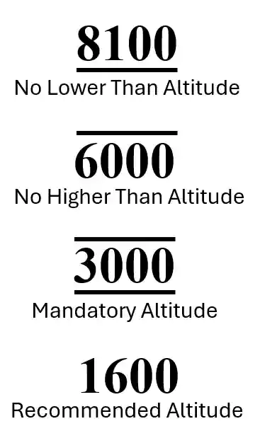
- Vertical guidance is published as minimum, maximum, mandatory, and recommended altitudes. []
- Minimum altitudes are underscored.
- Aircraft are required to maintain altitude at or above the depicted value.
- Maximum altitudes are overscored.
- Aircraft are required to maintain altitude at or below the depicted value.
- Mandatory altitudes are both underscored and overscored.
- Aircraft are required to maintain altitude at the depicted value.
- Recommended altitudes are neither overscored nor underscored.
- These altitudes are depicted for descent planning.
- Minimum altitudes are underscored.
- Pilots must adhere to prescribed altitudes because, in certain instances, they may be used as the basis for vertical separation of aircraft by ATC.
- When a depicted altitude is specified in the ATC clearance, that altitude becomes mandatory as defined above.
- The ILS glide slope is intended to be intercepted at the published glide slope intercept altitude.
- This point marks the Precise Final Approach Fix (PFAF) and is depicted by the "lightning bolt" symbol on U.S. Government charts.
- Intercepting the glide slope at this altitude marks the beginning of the final approach segment and ensures required obstacle clearance during descent from the glide slope intercept altitude to the lowest published decision altitude for the approach.
- If the pilot chooses to track the glide slope before the glide slope interception altitude, they remain responsible for complying with published altitudes for any preceding step-down fixes encountered during the subsequent descent.
- Approaches used for simultaneous (parallel) independent and simultaneous close parallel operations procedurally require descending on the glide-slope from the altitude at which the approach clearance is issued.
- For simultaneous close parallel (PRM) approaches, the Attention All Users Page (AAUP) may publish a note which indicates that descending on the glide-slope/glidepath meets all crossing restrictions.
- However, if no such note is published, and for simultaneous independent approaches (4300 and greater runway separation) where an AAUP is not published, pilots are cautioned to monitor their descent on the glide-slope/path outside of the PFAF to ensure compliance with published crossing restrictions during simultaneous operations.
- When parallel approach courses are less than 2500 feet apart and reduced in-trail spacing is authorized for simultaneous dependent operations, a chart note will indicate that simultaneous operations require use of vertical guidance and that the pilot should maintain last assigned altitude until established on glide slope. These approaches procedurally require utilization of the ILS glide slope for wake turbulence mitigation. Pilots should not confuse these simultaneous dependent operations with (SOIA) simultaneous close parallel PRM approaches, where PRM appears in the approach title
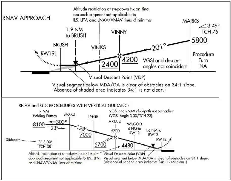
- Altitude restrictions depicted at stepdown fixes within the final approach segment are applicable only when flying a Non-Precision Approach to a straight-in or circling line of minima identified as a MDA(H). These altitude restrictions may be annotated with a note "LOC only" or "LNAV only." Stepdown fix altitude restrictions within the final approach segment do not apply to pilots using Precision Approach (ILS) or Approach with Vertical Guidance (LPV, LNAV/VNAV) lines of minima identified as a DA(H), since obstacle clearance on these approaches is based on the aircraft following the applicable vertical guidance. Pilots are responsible for adherence to stepdown fix altitude restrictions when outside the final approach segment (i.e., initial or intermediate segment), regardless of which type of procedure the pilot is flying []
-
Visual Descent Point:
- The Visual Descent Point, or VDP, identified by the symbol (V), is a point on the final approach course of a non-precision straight-in approach procedure from which a stabilized visual descent from the MDA to the runway touchdown point may be made with the runway environment in sight. []
- While VDPs are published on most RNAV IAPs, VDPs only apply to aircraft utilizing LP or LNAV minima, not LPV or LNAV/VNAV minimums (i.e., it applies to approaches without vertical guidance, hence non-precision).
- The pilot should not descend below the MDA before reaching the VDP.
- The VDP will be identified by DME or RNAV along-track distance to the MAP.
- The VDP distance is based on the lowest MDA published on the IAP and harmonized with the angle of the visual glide slope indicator (VGSI) (if installed) or the procedure VDA (if no VGSI is installed).
- A VDP is not published under certain circumstances which may result in a destabilized descent between the MDA and the runway touchdown point.
- Circumstances include an obstacle penetrating the visual surface between the MDA and the runway threshold, a lack of distance-measuring capability, or a procedure design that prevents a VDP from being identified.
- Pilots not equipped to receive the VDP should fly the approach procedure as though no VDP had been provided.
-
Profile View Sequential Missed Approach Procedure:
- To make missed approach guidance easier to understand, approach charts display missed approach procedures in the profile view as a sequence of quick-reference icons.
- Due to limited space in the profile area, only four or fewer icons can be shown.
- The icons may not provide representation of the entire missed approach procedure.
- The entire set of textual missed approach instructions are provided in the pilot briefing section. []
-
Instrument Approach Procedure Step-down Fixes
-
Approach Minimums:
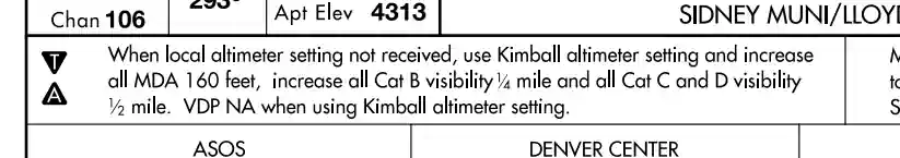
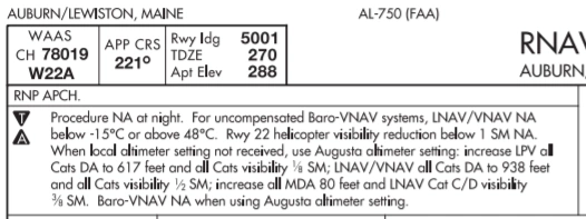
- Approach minimums are based on the local altimeter setting for that airport, unless annotated otherwise []
- When a different altimeter source is required, or more than one source is authorized, it will be annotated on the approach chart.
- Approach minimums may be raised when using an authorized non-local altimeter source.
- When more than one altimeter source is authorized, and the minima are different, they will be shown by separate lines in the approach minima box or a note.
-
Alternative Altimeter Setting - The altimeter source location may be referenced by city name, city and state, airport name, or the FAA location identifier.
- When using the location identifier, an airport outside the contiguous U.S. will use both the FAA and ICAO identifiers.
- New approach procedures and future amendments of existing procedures will use airport identifiers as the standard reference.
- When the altimeter must be obtained from a source other than air traffic a note will indicate the source; e.g., Obtain local altimeter setting on CTAF. When the altimeter setting(s) on which the approach is based is not available, the approach is not authorized.
- Baro−VNAV must be flown using the local altimeter setting only.
- Where no local altimeter is available, the LNAV/VNAV line will still be published for use by WAAS receivers with a note that Baro−VNAV is not authorized.
- When a local and at least one other altimeter setting source is authorized and the local altimeter is not available Baro−VNAV is not authorized; however, the LNAV/VNAV minima can still be used by WAAS receivers using the alternate altimeter setting source.
- NOTE-Barometric Vertical Navigation (baro-VNAV). An RNAV system function which uses barometric altitude information from the aircraft's altimeter to compute and present a vertical guidance path to the pilot. The specified vertical path is computed as a geometric path, typically computed between two waypoints or an angle based computation from a single waypoint. Further guidance may be found in Advisory Circular 90-105
-
Instrument Approach Categories:
-
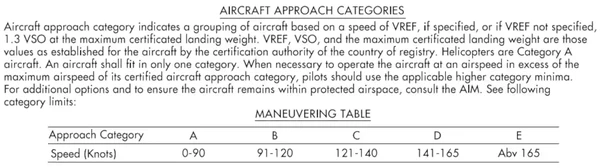
Final Approach Obstacle Clearance - Aircraft approach categories are groupings of aircraft based on VREF at the maximum certified landing weight, if specified, or 1.3 VSO at the maximum certified landing weight (if VREF is not specified).
- Aircraft categories therefore maintain TERPS criteria based on expected performance, directly effecting the approach minimums.
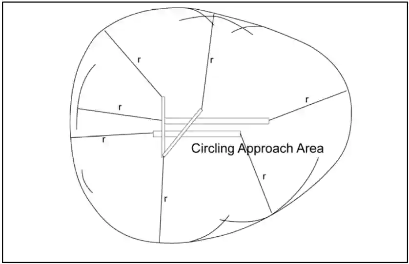
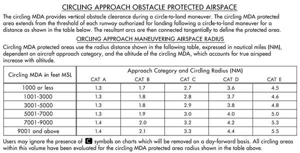
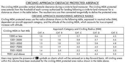
- When circling, pilots must maneuver the aircraft within the circling approach protected area to achieve the obstacle and terrain clearances provided by procedure design criteria. []
- Protected areas are defined as a radius (in NM) from the airport, and is published in the circling approach maneuvering radius table in the approach charts.
- In addition to pilot techniques for maneuvering, one acceptable method to reduce the risk of flying out of the circling approach protected area is to use either the minima corresponding to the category determined during certification or minima associated with a higher category.
- Helicopters may use Category A minima. If it is necessary to operate at a speed in excess of the upper limit of the speed range for an aircraft's category, the minimums for the higher category should be used. This may occur with certain aircraft types operating in heavy/gusty wind, icing, or non-normal conditions. For example, an airplane which fits into Category B, but is circling to land at a speed of 145 knots, should use the approach Category D minimums. As an additional example, a Category A airplane (or helicopter) which is operating at 130 knots on a straight-in approach should use the approach Category C minimums
- A pilot who chooses an alternative method when it is necessary to maneuver at a speed that exceeds the category speed limit (for example, where higher category minimums are not published) should consider the following factors that can significantly affect the actual ground track flown:
- Bank angle. For example, at 165 knots groundspeed, the radius of turn increases from 4,194 feet using 30 degrees of bank to 6,654 feet when using 20 degrees of bank. When using a shallower bank angle, it may be necessary to modify the flightpath or indicated airspeed to remain within the circling approach protected area. Pilots should be aware that excessive bank angle can lead to a loss of aircraft control
- Indicated airspeed. Procedure design criteria typically utilize the highest speed for a particular category. If a pilot chooses to operate at a higher speed, other factors should be modified to ensure that the aircraft remains within the circling approach protected area
- Wind speed and direction. For example, it is not uncommon to maneuver the aircraft to a downwind leg where the groundspeed will be considerably higher than the indicated airspeed. Pilots must carefully plan the initiation of all turns to ensure that the aircraft remains within the circling approach protected area
- Pilot technique. Pilots frequently have many options with regard to flightpath when conducting circling approaches. Sound planning and judgment are vital to proper execution. The lateral and vertical path to be flown should be carefully considered using current weather and terrain information to ensure that the aircraft remains within the circling approach protected area
- It is important to remember that 14 CFR Section 91.175(c) requires that "where a DA/DH or MDA is applicable, no pilot may operate an aircraft below the authorized MDA or continue an approach below the authorized DA/DH unless the aircraft is continuously in a position from which a descent to a landing on the intended runway can be made at a normal rate of descent using normal maneuvers, and for operations conducted under Part 121 or Part 135 unless that descent rate will allow touchdown to occur within the touchdown zone of the runway of intended landing"
- See approach and landing minimums page for greater detail on what is required to continue an approach
Category A:
Speed less than 91 knotsCategory B:
Speed 91 knots or more but less than 121 knotsCategory C:
Speed 121 knots or more but less than 141 knotsCategory D:
Speed 141 knots or more but less than 166 knotsCategory E:
Speed 166 knots or more- VREF in the above definition refers to the speed used in establishing the approved landing distance under the airworthiness regulations constituting the type certification basis of the airplane, regardless of whether that speed for a particular airplane is 1.3 VSO, 1.23 VSR, or some higher speed required for airplane controllability. This speed, at the maximum certificated landing weight, determines the lowest applicable approach category for all approaches regardless of actual landing weight
-
-
TERPS Criteria:
-
Precision Approach Criteria:
- Precision Approaches (PAs) are instrument approaches based on a navigation system that provides course and glidepath deviation information meeting the precision standards of ICAO Annex 10.
- Examples include: PAR, ILS, and GLS approaches.
- Precision Approaches (PAs) are instrument approaches based on a navigation system that provides course and glidepath deviation information meeting the precision standards of ICAO Annex 10.
-
Approach with Vertical Guidance:
- Approaches with Vertical Guidance (APVs) are instrument approaches based on a navigation system that is not required to meet the precision approach standards of ICAO Annex 10, but provides course and glidepath deviation information.
- This means vertical guidance is just that, guidance, and therefore not a precision approach.
- Examples include: Baro-VNAV, LDA with glidepath, LNAV/VNAV, and LPV approaches.
- Approaches with Vertical Guidance (APVs) are instrument approaches based on a navigation system that is not required to meet the precision approach standards of ICAO Annex 10, but provides course and glidepath deviation information.
-
Non-Precision Approach (NPA):
- A Non-Precision Approach (NPA) is an instrument approach based on a navigation system that provides course deviation information, but no glidepath deviation information.
- Examples include: VOR, NDB, and LNAV approaches.
- Some approach procedures may provide a Vertical Descent Angle (VDA) as an aid in flying a stabilized approach.
- While a VDA may be provided, the approach is designed without requiring its use and so this does not make the approach an APV procedure, since it must still be flown to an MDA and has not been evaluated with a glidepath.
- A Non-Precision Approach (NPA) is an instrument approach based on a navigation system that provides course deviation information, but no glidepath deviation information.
- Detailed TERPS criteria is outlined in Federal Aviation Administration Order - 8260.3.
-
-
Airport Diagram:
- The airport diagram provides a general overview of the airfield and gives you some orientation on what to expect when you break out of the weather.
- The diagram is not overly specific, and many airports publish a separate full-sized diagram with the approach plates that follow all procedures.


Approach Briefings
- Airports can have multiple approaches to multiple runways which periodically change, making memorizing approach procedures both unrealistic and unsafe.
- Therefore, it is through the approach briefing that pilots and crew familiarizes and sets expectations for the pilot and/or crew, keeping the aircrew ahead of the aircraft.
-
Briefing Contents:
-

Instrument Flying Handbook,
Instrument Approach Chart - Approach plates are logically sequenced to allow for the flow of an approach briefing. []
- Starting with the pilot briefing and procedure notes, the pilot covers administrative information such as:
- Approach name, airport, and page number (as required).
- Runway information, elevation.
- Approach notes.
- Approach lighting expected.
- Terminal area frequencies such as ATIS/AWOS, approach, and tower.
- The weather information provided allows for calculating crosswind components and expected performance parameters.
- Brief what applies (i.e., don't brief clearance frequencies unless you expect to talk to them) and abbreviate as appropriate (i.e., ground will be on 0.4).
- The plan view doesn't offer much to discuss, but this section provides spatial awareness of the points and courses listed in the profile view.
- The profile view provides detailed information that covers:
- Step altitudes.
- Courses, to include the Final Approach Course.
- Fixes, to include the Final Approach Fix.
- The missed approach or climb-out instructions.
- Timing, as required.
- Wake turbulence.
- This information feeds into the final portion of the approach, where the pilot needs to be aware of the minimum altitudes.
- In the minimums section, you can determine:
- Category.
- Weather minimums.
- Speeds.
- Decision Height (DH) or MDA.
- Lastly, the airport diagram enhances spatial awareness of the aircraft's orientation upon breaking out of the weather.
- Be sure to focus on items that are unusual or otherwise noteworthy.
- These items can be from the plate (notable terrain) or restrictions provided by Air Traffic Control.
-
-
Approach Briefing Example:
- "We will be flying the VOR runway 16 approach into Daytona Beach International on page 22 of the Florida plates. The minimum weather requirements are 800 and 1. NAVAIDs are being tuned and set to 112.6 and 73x. We will fly to the IAF and turn outbound 336 down to 1600. Procedure turn back in on 156 until the FAF, where we will start the time and begin a descent to our MDA of 760. Our missed approach point will be 7.4 DME from the VORTAC. Missed approach instructions are climbing straight out at 2000 on the 161 radial to SMYRA to hold. We are on approach, set tower (as appropriate)."
-
Approach Briefing Common Errors:
- Briefing each number or word verbatim rather than by exception.
- Briefing information as it appears rather than how it applies.
- Ensure you reference the correct approach plate for both the correct approach type and runway.
- Not reviewing the symbology on an approach plate (i.e., mistaking a no lower than for a no higher than).
- Using the wrong frequency to contact a specific agency.
- Not preparing for the next phase of flight, including post-landing taxi.
-
Approach Briefing Conclusion:
- It is not necessary to go into such detail as to read each frequency, but rather to discuss the flow.
- Pilots must balance the requirement to brief essential elements while aviating, navigating, and communicating.
- Although not required by regulations for general aviation (part 91), they are a great idea to do regardless of experience level to make sure you plan correctly.
- The completeness and clarity of the approach brief are indicators of how well you are about to fly the approach.
- The briefing is for you, so tailor it however you want.
- Over time, your experiences may change, leading to constant re-development of your approach brief.
- Practice even when flying under Visual Flight Rules (VFR) so you can be proficient when operating under Instrument Flight Rules (IFR).
RNP/AR Instrument Approach Procedures
- RNP AR procedures require authorization analogous to the special authorization required for Category II or III ILS procedures
- All operators require specific authorization from the FAA to fly any RNP AR approach or departure procedure
- The FAA issues RNP AR authorization via operations specification (OpSpec), management specification (MSpec), or letter of authorization (LOA)
- There are no exceptions. Operators can find comprehensive information on RNP AR aircraft eligibility, operating procedures, and training requirements in AC 90-101, Approval Guidance for RNP Procedures with AR
-
Unique Characteristics of RNP AR Operations Approach Title
- The FAA titles all RNP AR instrument approach procedures (IAP) as "RNAV (RNP) RWY XX"
- Internationally, operators may find RNP AR IAPs titled "RNP RWY XX (AR)
- All RNP AR procedures will clearly state "Authorization Required" on the procedure chart
-
RNP value:
- RNP AR procedures are characterized by use of a lateral Obstacle Evaluation Area (OEA) equal to two times the RNP value (2 x RNP) in nautical miles
- No secondary lateral OEA or additional buffers are used
- RNP AR procedures require a minimum lateral accuracy value of RNP 0.30
- Each published line of minima in an RNP AR procedure has an associated RNP value that defines the procedure's lateral performance requirement in the Final Approach Segment
- Each approved RNP AR operator's FAA-issued authorization will identify a minimum authorized RNP approach value
- This value may vary depending on aircraft configuration or operational procedures (e.g., use of flight director or autopilot)
- RNP AR procedures are characterized by use of a lateral Obstacle Evaluation Area (OEA) equal to two times the RNP value (2 x RNP) in nautical miles
-
Radius-to-fix (RF) legs:
- Many RNP AR IFPs contain RF legs
- Aircraft eligibility for RF legs is required in any authorization for RNP AR operations
-
Missed Approach RNP value less than 1.00 NM:
- Some RNP AR IFPs require an RNP lateral accuracy value of less than 1.00 NM in the missed approach segment
- The operator's FAA-issued RNP AR authorization will specify whether the operator may fly a missed approach procedure requiring a lateral accuracy value less than 1.00 NM
- AC 90-101 identifies specific operating procedures and training requirements applicable to this aspect of RNP AR procedures
-
Non-standard Speeds or Climb Gradients:
- RNP AR approaches may require non-standard approach speeds and/or missed approach climb gradients
- RNP AR approach charts will reflect any non-standard requirements and pilots must confirm they can meet those requirements before commencing the approach
-
RNP AR Departure Procedures (RNP AR DP):
- RNP AR approach authorization is a mandatory prerequisite for an operator to be eligible to perform RNP AR DPs []
- RNP AR DPs can utilize a minimum RNP value of RNP 0.30, may include higher than standard climb gradients, and may include RF turns
- Close in RF turns associated with RNP AR DPs may begin as soon as the departure end of the runway (DER)
- For specific eligibility guidance, operators should refer to AC 90-101
- The FAA titles all RNP AR instrument approach procedures (IAP) as "RNAV (RNP) RWY XX"

Minimum Vectoring Altitudes
- Minimum Vectoring Altitudes (MVAs) provide ATC with guidance on obstacle clearance when exercising radar control.
- It is the pilot's responsibility to avoid obstacles until at or above the minimum vectoring altitude.
- Air traffic facilities prepare MVA charts at locations where there are numerous different minimum IFR altitudes.
- Each MVA chart has sectors large enough to accommodate vectoring of aircraft within the sector at or above the MVA.
- Each sector boundary is at least 3 miles from the obstruction determining the MVA.
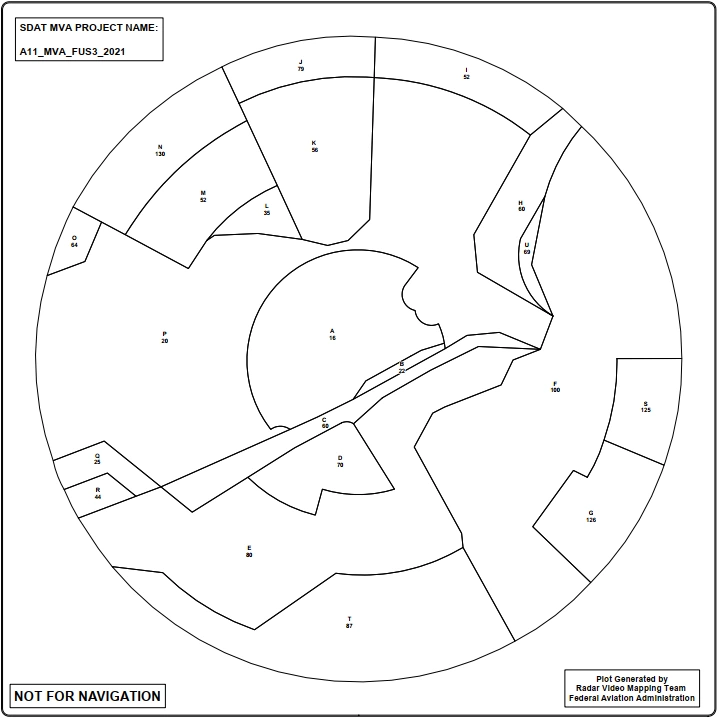
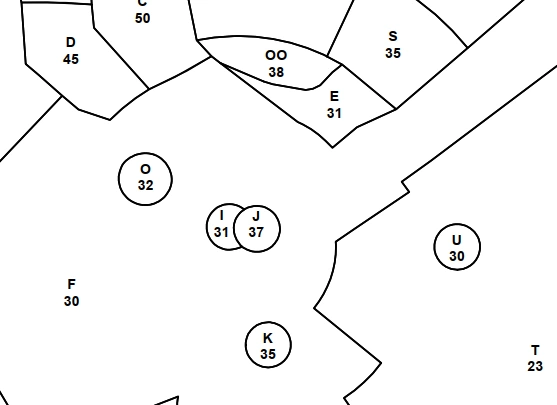
- To avoid creating a large sector with an excessively high MVA due to a single prominent obstruction, the FAA may place the obstruction within a buffer area whose boundaries extend at least 3 miles from it. [Figure x]
- The minimum vectoring altitude in each sector provides 1,000 feet above the highest obstacle in non-mountainous areas and 2,000 feet above the highest obstacle in designated mountainous areas. Where lower MVAs are required in designated mountainous areas to achieve compatibility with terminal routes or to permit vectoring to an IAP, the FAA may authorize 1,000 feet of obstacle clearance with the use of ATC surveillance. The minimum vectoring altitude is at least 300 feet above the floor of controlled airspace.
- OROCA is a published altitude which provides 1,000 feet of terrain and obstruction clearance in the U.S. (2,000 feet of clearance in designated mountainous areas). NAVAID signal coverage, air traffic control surveillance, or communications coverage are not guaranteed. OROCAs provide general situational awareness, flight planning, and in-flight contingency use.
- Because of differences in the areas considered for MVA, and those applied to other minimum altitudes, and the ability to isolate specific obstacles, some MVAs may be lower than the non-radar Minimum En Route Altitudes (MEAs), Minimum Obstruction Clearance Altitudes (MOCAs), or other minimum altitudes depicted on charts for a given location. While being radar vectored, IFR altitude assignments by ATC will be at or above MVA.
- The MVA/Minimum IFR altitude (MIA) may be lower than the TAA minimum altitude. If ATC assigns an altitude below the TAA minimum, the controller will either assign an altitude to maintain until the aircraft is established on a segment of a published route or instrument approach procedure, or will climb the aircraft to the TAA altitude.
- When operating on an unpublished route or while being radar vectored, the pilot, when an approach clearance is received, shall:
- Comply with minimum altitudes for IFR operations:
- Maintain the last assigned attitude, unless a different is assigned or until the aircraft is established on a segment of a published route or IAP.
- After the aircraft is established, published altitudes apply to descent within each succeeding route or approach segment unless a different altitude is assigned by ATC. Notwithstanding this pilot responsibility, for aircraft operating on unpublished routes or while being radar vectored, ATC will, except when conducting a radar approach, issue an IFR approach clearance only after the aircraft is established on a segment of a published route or IAP, or assign an altitude to maintain until the aircraft is established on a segment of a published route or instrument approach procedure. For this purpose, the procedure turn of a published IAP must not be considered a segment of that IAP until the aircraft reaches the initial fix or navigation facility upon which the procedure turn is predicated.
- Cross Redding VOR at or above five thousand, cleared VOR runway three four approach. or Five miles from outer marker, turn right heading three three zero, maintain two thousand until established on the localizer, cleared ILS runway three six approach
- The assigned altitude will ensure IFR obstruction clearance from the point at which the approach clearance is issued until established on a segment of a published route or IAP. If uncertain of the meaning of the clearance, immediately request clarification from ATC.
- An aircraft is not established on an approach while below published approach altitudes. If the MVA/MIA allows, and ATC assigns an altitude below an IF or IAF altitude, the pilot will be issued an altitude to maintain until past a point that the aircraft is established on the approach.
Instrument Approach Segments
- Instrument approaches are primarily broken up into initial, intermediate, final (includes a visual segment), and missed approach segments, instrument approaches create a "road" maps for the sky for the terminal area.
-
Initial Approach Segment:
-
Intermediate Approach Segment:
-
Final Approach Segment:
-
Visual Segment
- When passing the visual descent point on the final approach segment, the pilot is entering the visual segment.
- A visual segment obstruction evaluation is accomplished during procedure design on all IAPs. Obstacles (both lighted and unlighted) are allowed to penetrate the visual segment obstacle identification surfaces. Identified obstacle penetrations may cause restrictions to instrument approach operations which may include an increased approach visibility requirement, not publishing a VDP, and/or prohibiting night instrument operations to the runway. There is no implicit obstacle protection from the MDA/DA to the touchdown point. Accordingly, it is the responsibility of the pilot to visually acquire and avoid obstacles below the MDA/DA during transition to landing
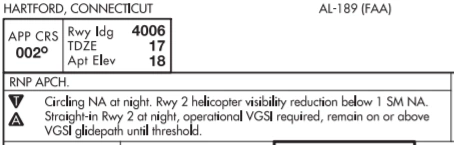
- Unlighted obstacle penetrations (breaking 20:1 obstruction clearance standards) may result in prohibiting night instrument operations to the runway. A chart note will be published in the pilot briefing strip "Procedure NA at Night" []
- Use of a VGSI may be approved in lieu of obstruction lighting to restore night instrument operations to the runway. A chart note will be published in the pilot briefing strip "Straight-in Rwy XX at Night, operational VGSI required, remain on or above VGSI glidepath until threshold" []
- Obstacles (man-made, terrain, or vegetation) are charted on the planview of an IAP
- The elevation of the charted obstacle will be shown to the nearest foot above mean sea level
- Other obstacles may be charted in either the planview or the airport sketch based on distance from the runway and available chart space
- The highest obstacle (man-made, terrain, or vegetation) will be indicated on the planview of an IAP with a larger font size
- Obstacles without a verified accuracy are indicated by a ± symbol following the elevation value []
- If not VDP is present, the pilot may create their own for reference by dividing altitude to lose (MDA altitude minus TDZE) by 300
- Creating a reference VDP allows the pilot to calculate a safe descent rate to landing, that if not executed (runway not yet in sight), means the rate of descent required is only going to increase
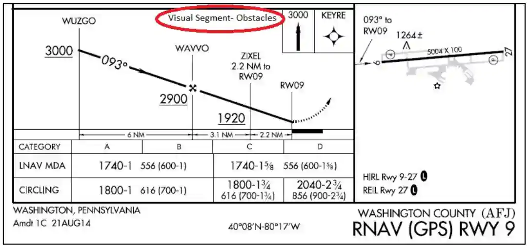
- Lack of a VDP likely includes a note "visual segment - obstalces" to provide warning that good visibility is necessary to descend
-
Visual Descent Angle:
- FAA policy is to publish Vertical Descent Angles (VDAs) on all non-precision approaches except those published in conjunction with vertically guided minimums or no-FAF procedures without step-down fixes. A VDA does not guarantee obstacle protection below the MDA in the visual segment. The presence of a VDA does not change any nonprecision approach requirements
- Obstacles may penetrate the obstacle identification surface below the MDA in the visual segment of an IAP that has a published VDA/TCH. When the VDA/TCH is not authorized due to an obstacle penetration that would require a pilot to deviate from the VDA between MDA and touchdown, the VDA/TCH will be replaced with the note "Visual Segment Obstacles" in the profile view of the IAP (See FIG 5-4-13). Accordingly, pilots are advised to carefully review approach procedures to identify where the optimum stabilized descent to landing can be initiated. Pilots that follow the previously published descent angle, provided by the RNAV system, below the MDA on procedures with this note may encounter obstacles in the visual segment. Pilots must visually avoid any obstacles below the MDA
- VDA/TCH data is furnished by FAA on the official source document for publication on IAP charts and for coding in the navigation database unless, as noted previously, replaced by the note "Visual Segment - Obstacles"
- Commercial chart providers and navigation systems may publish or calculate a VDA/TCH even when the FAA does not provide such data. Pilots are cautioned that they are responsible for obstacle avoidance in the visual segment regardless of the presence or absence of a VDA/TCH and associated navigation system advisory vertical guidance
- The threshold segment height (TCH) used to compute the descent angle is published with the VDA. The VDA and TCH information are charted on the profile view of the IAP following the fix (FAF/stepdown) used to compute the VDA. If no PA/APV IAP is establish to the same runway, the VDA will be equal to or higher than the glide path angle of the VGSI installed on the same runway provided it is within instrument procedure criteria. A chart note will indicate if the VGSI is not coincident with the VDA. Pilots must be aware that the published VDA is for advisory information only and not to be considered instrument procedure derived vertical guidance. The VDA solely offers and aid to help pilots establish a continuous, stabilized descent during final approach
- Pilots may use the published angle and estimated/actual groundspeed to find a target rate of descent from the rate of descent table published in the back of the U.S. Terminal Procedures Publication. This rate of descent can be flown with the Vertical Velocity Indicator (VVI) in order to use the VDA as an aid to flying a stabilized descent. No special equipment is required
- A straight-in aligned procedure may be restricted to circling only minimums when an excessive descent gradient necessitates. The descent angle between the FAF/stepdown fix and the Circling MDA must not exceed the maximum descent angle allowed by TERPS criteria. A published VDA on these procedures does not imply that landing straight ahead is recommended or even possible. The descent rate based on the VDA may exceed the capabilities of the aircraft and the pilot must determine how to best maneuver the aircraft within the circling area in order to land safely
- Obstacles may penetrate the obstacle identification surface below the MDA in the visual segment of an IAP that has a published VDA/TCH. When the VDA/TCH is not authorized due to an obstacle penetration that would require a pilot to deviate from the VDA between MDA and touchdown, the VDA/TCH will be replaced with the note "Visual Segment Obstacles" in the profile view of the IAP (See FIG 5-4-13). Accordingly, pilots are advised to carefully review approach procedures to identify where the optimum stabilized descent to landing can be initiated. Pilots that follow the previously published descent angle, provided by the RNAV system, below the MDA on procedures with this note may encounter obstacles in the visual segment. Pilots must visually avoid any obstacles below the MDA
- IAPs may contain a published visual flight path. These procedures are annotated "Fly Visual to Airport" or "Fly Visual"
- A dashed arrow indicating the visual flight path will be included in the profile and plan views with a defined flightpath or approximate heading and distance to the end of the runway.
- The depicted ground track or flightpath associated with the "Fly Visual to Airport" segment should be flown with flight instrumentation (when advisory lateral and vertical guidance is provided) and/or pilotage or dead reckoning navigation techniques. When executing the "Fly Visual to Airport" segment, the flight visibility must not be less than that prescribed in the IAP; the pilot must remain clear of clouds and proceed to the airport maintaining visual contact with the ground. Altitude on the visual flight path is at the discretion of the pilot, and recommended altitudes may be shown, but it is the responsibility of the pilot to visually acquire and avoid obstacles in the "Fly Visual to Airport" segment.
- It is therefore not a requirement to have the airport environment in sight to fly this segment
- Missed approach obstacle clearance is assured only if the missed approach is commenced at or above the MDA/DA and flown from the published MAP. Before initiating an IAP that contains a "Fly Visual to Airport" segment, the pilot should have preplanned climb out options based on aircraft performance and terrain features. Obstacle clearance is the responsibility of the pilot when the missed approach maneuver is initiated below the MDA/DA or when the approach is continued beyond the MAP
- Note: The FAA Administrator retains the authority to approve instrument approach procedures where the pilot, on arrival at the MDA/DA on the prescribed flightpath, may not necessarily have one of the visual references specified in 14 CFR § 91.175 and related rules. While it is not a function of procedure design to ensure compliance with § 91.175, the pilot is always required to assess prevailing flight visibility against the published minima. When published on the procedure, the annotation "Fly Visual to Airport" provides specific relief only from §91.175 (c)(3)(i) through (x) requirements that the pilot have distinctly visible and identifiable visual references prior to descent below MDA/DA.
-
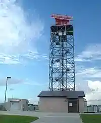
Radar Approaches
- Precision Approach Radars (PARs) and Airport Surveillance Radars (ASRs) provide air traffic control with situational awareness of the airport environment and enable controllers to monitor the progress of other instrument approaches.
- These radars can also provide pilots with Ground Control Approaches (GCAs), which use radar rather than aircraft equipment to provide approach services.
- The radar controller vectors the aircraft to align it with the runway centerline and continues the vectors to keep the aircraft on course until the pilot can complete the approach and landing by visual reference to the surface.
- The only airborne radio equipment required for radar approaches is a functioning radio transmitter and receiver.
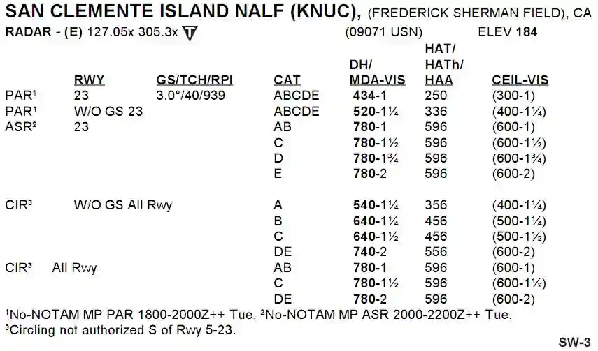
- The FAA Terminal Procedures Publication (TPP) publishes PAR and ASR approach minimums. []
- Radar approaches are available to pilots upon request.
- Radar approaches are beneficial to pilots of aircraft in distress.
- Acceptance of a PAR or ASR by a pilot does not waive the prescribed weather minimums for the airport or for the particular aircraft operator concerned.
- The decision to make a radar approach when the reported weather is below the established minimums is the pilot's responsibility.
- Normally, navigational guidance will be provided until the aircraft reaches the MAP.
- The controller shall issue instructions to execute a missed approach or to climb and maintain a specific altitude and fly a specified course whenever the completion of a safe approach is questionable, because one or more of the following conditions exist:
- Safe limits are exceeded or radical aircraft deviations are observed.
- Position or identification of the aircraft is in doubt.
- Radar contact is lost or a malfunctioning radar is suspected.
- Field conditions, conflicting traffic, or other unsafe conditions observed from the tower prevent approach completion.
- Two classes of radar approaches:
-
Radar Approach Definitions:
- RWY: runway on which the approach applies.
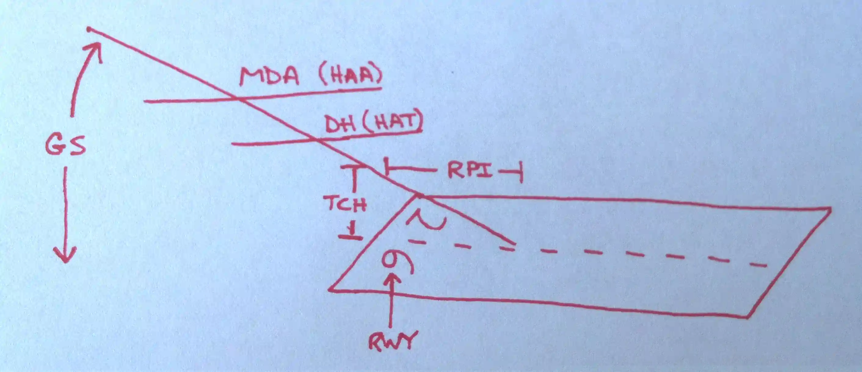
- GS: glide slope angle.
- TCH: threshold crossing height.
- RPI: runway point of intercept.
- CAT: category of aircraft.
- DH: decision height (PAR).
- MDA: minimum descent altitude (ASR).
- VIS: visibility required to shoot the respective approach.
- HAT: height above touchdown (straight in).
- HATh: height above threshold height.
- HAA: height above airport (circling).
- CEIL-VIS: ceiling - visibility.
-
Surveillance Approach Radar
- The radar itself scans 360° of azimuth.
- ASR can be used to advise pilots on other approaches so long as they are coincident with the PAR final and the PAR is in service.
- A Surveillance Approach Radar (ASR) is a non-precision approach that provides lateral course guidance (azimuth) but no glide slope.
- The lack of vertical guidance results in higher approach minimums, as you would expect with a non-precision approach.
- If requested by the pilot, recommended altitudes will be issued at each mile, based on the descent gradient established for the procedure, down to the last mile that is at or above the MDA.
- ATC furnishes headings for the pilot to fly to align the aircraft with the extended centerline of the landing runway.
- In addition, the pilot will be advised of the location of the Missed Approach Point (MAP) prescribed for the procedure and the aircraft's position each mile on final from the runway, airport, or heliport or MAP, as appropriate.
- Similarly, guidance termination and missed approach will be effected upon pilot request and, for civil aircraft only, controllers may terminate guidance when the pilot reports the runway, airport/heliport or visual surface route (point-in-space approach) in sight or otherwise indicates that continued guidance is not required.
-
Precision Approach Radar:
- A Precision Approach Radar (PAR) approach is one in which a controller provides highly accurate navigational guidance in azimuth and elevation to a pilot.
- Pilots are given headings to fly, to direct them to, and keep their aircraft aligned with the extended centerline of the landing runway.
- They are told to anticipate glidepath interception approximately 10 to 30 seconds before it occurs and when to start descent.
- The published Decision Height is published in the approach plates and therefore will only be if the pilot requests it. []
- If the aircraft is observed to deviate above or below the glidepath, the pilot is given the relative amount of deviation by use of terms "slightly" or "well" and is expected to adjust the aircraft's rate of descent/ascent to return to the glidepath.
- Trend information is also issued with respect to the aircraft's elevation and may be modified by the terms "rapidly" and "slowly"; e.g., "well above glidepath, coming down rapidly."
- The range from touchdown is given at least once every mile.
- Navigational guidance in azimuth and elevation is provided the pilot until the aircraft reaches the published Decision Height (DH).
- Advisory course and glidepath information is furnished by the controller until the aircraft passes over the landing threshold, at which point the pilot is advised of any deviation from the runway centerline.
- Radar service is automatically terminated upon completion of the approach.
- Provides azimuth and glide slope (range and elevation).
- Two antennas are used, one scanning the vertical and the other horizontal planes.
- Limited to 10 NM range.
- Limited to 20° azimuth.
- Limited to 7° elevation.
- Each scope is divided into two parts:
- The upper half presents altitude and distance information, and;
- The lower half presents azimuth and distance.
- Limits are due to the fact that only the final approach is covered on a PAR.
- Terms like "rapidly" or "slowly" or "well" or "slight" are used to describe position from desired course.
- Should always be paired with an ILS if available as a NORDO/sanity backup.
-
Airport Surveillance Radar Approach Procedure:
WARNING:
All procedures are GENERALIZED.
Fly the maneuver in accordance with the Pilot Operating Handbook (POH).
and/or current Standard Operating Procedures (SOPs).- Initial Pattern:
- Guided by surveillance radar.
- Includes all maneuvering up to the point at which your aircraft is inbound on the FAC at approximately 8nm from touchdown.
- During transition to final, the controller will direct your headings and altitudes.
- All controller instructions to initiate turns and descents should be complied with immediately.
- Do not exceed 30° AoB.
- Final Pattern:
- Angle of Bank (AoB) should approximate the number of degrees to be turned, not to exceed 1/2 standard rate (about 10°).
- These gates keep you stable and predictable.
- Example: 2° of heading change should use a very shallow 2° AoB.
- Angle of Bank (AoB) should approximate the number of degrees to be turned, not to exceed 1/2 standard rate (about 10°).
- Contact approach with your request.
- YOU: "[Facility], [Callsign], [Location], with information [ATIS], request."
- Example: Meridian Approach, Bobcat 12, 15 miles to the west with information Charlie requesting the ASR (or PAR), runway 19L."
- ATC: "[Callsign], [Facility], go ahead."
- YOU: "[Callsign], requesting [Approach]."
- YOU: "[Facility], [Callsign], [Location], with information [ATIS], request."
- Expect the following:
- Type of approach and duty runway.
- "This will be a PAR/ASR approach to runway 5."
- MDA (ASR Only).
- Location of missed approach point (ASR Only).
- Altimeter.
- Ceiling and visibility if below 1000' (or below highest circling minimum, whichever is greater) or visibility less than 3 miles.
- Special weather observations.
- Airport conditions important to the safe operation of the aircraft.
- Lost communication procedures "...if no transmissions received for 30 seconds (not more than 1 minute) in the pattern or five seconds on final, attempt contact on [Frequency] and proceed VFR, if unable, proceed with the TACAN approach."
- Missed approach instructions.
- Comply with the heading and altitude instructions issued by ATC.
- Maintain situational awareness to what "leg" of the pattern you are on.
- On the downwind, make sure to reference MSL and AGL DH/MDA.
- Set up your system for the approach.
- Perform 15 minute checks as required.
- Determine the desired rate of descent for the approach.
- Your rate of descent is calculated by half your ground speed x10 or by the descent chart on the back of the approach plates.
- GS: 160 then 16/2 = 800 FPM.
- GS: 150 then = 750 FPM.
- GS: 140 then = 700 FPM.
- GS: 130 then = 650 FPM.
- GS: 120 then = 600 FPM.
- Your rate of descent is calculated by half your ground speed x10 or by the descent chart on the back of the approach plates.
- When controller informs you that you are "on glide path" (PAR) or "begin descent" (ASR), extend speed brakes (as appropriate) and begin your descent.
- Upon commencing the approach at the Final Approach Fix (FAF), the pilot will be advised when to commence descent to the Minimum Descent Altitude (MDA) or, if appropriate, to an intermediate step-down fix Minimum Crossing Altitude and subsequently to the prescribed MDA.
- Set power and adjust pitch to establish and maintain the predetermined rate of descent necessary to ensure descending to and maintaining MDA prior to the missed approach point.
- The published MDA for straight-in approaches will be issued to the pilot before beginning descent.
- When a surveillance approach will terminate in a circle-to-land maneuver, the pilot must furnish the aircraft approach category to the controller.
- The controller will then provide the pilot with the appropriate MDA.
- Fly the pattern at cruise speed knots clean or as directed at assigned pattern altitude.
- Remain clean until within 10 NM of runway and 30 radials of the FAC.
- This should happen on a base leg, configure then set approach/on-speed.
- Expect ATC to remind you to "perform landing checks" if at a Naval installation.
- As part of the landing checklist, lower the LAW to 10% below HAA or HAT as required on an ASR or a HAT for a PAR.
- At the beginning of a PAR final approach, you will be straight and level approach/on-speed and normally at approximately 1,500' AGL.
- On the ASR final approach, the controller cannot furnish glide slope information.
- It will be up to you to establish and maintain the correct rate of descent.
- Recommended altitudes decrease 300' per mile on approximately a 3° glide slope.
- In order to smoothly level at MDA prior to the MAP, your altitudes should be slightly lower than those recommended.
- Depending on your ground speed, a descent rate of 500-700 FPM, maybe slightly higher than normal, will allow you to descend to the MDA prior to reaching the MAP.
- On an ASR you want to reach the MDA early but remember, ATC will not tell you when to level off.
- Perform the 5 T's.
- Time: note the time.
- Turn: To track the inbound course.
- Twist: Verify that the OBS is set to inbound courses.
- Throttle: Maintain 100 KIAS.
- Talk: Make required reports.
- Begin a descent to MDA when instructed by ATC
- Set power and adjust pitch to establish and maintain the predetermined rate of descent necessary to ensure descending to and maintaining MDA prior to the missed approach point
- ICS: "Speed brakes full, landing checklist complete."
- Set power and adjust pitch to establish and maintain the predetermined rate of descent necessary to ensure descending to and maintaining MDA prior to the missed approach point
- Make lateral course corrections as instructed by ATC.
- Use 30° Angle of Bank (AoB) in pattern (clean).
- At 1000' above MDA, call out, "1000 above MDA."
- ATC will advice from tower a clearance to land.
- Use 20° AoB turning base to final (dirty).
- Not to exceed 10° AoB on final or dogleg.
- At 500' above MDA, call out, "500 above MDA," and complete a GUMP check
- At 100' above MDA, call out, "100' above MDA."
- Level off at the MDA, set power to maintain altitude, and set pitch.
- As you near the decision height, begin an inside/outside scan to visually acquire the runway environment.
- Initiate a descent from DA when the runway environment is in sight.
- Descend no lower than 100' above touchdown zone elevation when referencing the approach light system without seeing the red terminating bars or red side-row bars.
With the runway in sight:
- When the runway is in sight, and you are sure you can take it from here to a safe landing, call "Taking over visually."
- With the runway in sight and at the VDP, or, where no VDP is provided, in a position from which a descent to a landing on the intended runway can be made at a normal rate of descent using normal maneuvers, callout (over the ICS) "Runway in Sight, Landing."
- Descend no lower than 100' above touchdown zone elevation when referencing the approach light system without seeing the red terminating bars or red side-row bars.
- ATC will tell you to proceed visually.
- Switch to the tower once instructed.
- Set power and flaps appropriate for landing.
With no runway in sight:
- If you do not have the runway environment in sight when you reach the DH/MAP, execute a missed approach when instructed (make the mandatory missed approach call).
- If no visual reference is in sight, continue to the missed approach point.
- At the missed approach point, call out, "Missed approach," and execute a go-around, complying with the published missed approach procedure, or as directed.
- Radar service is automatically terminated at the completion of a radar approach.
-
Lost Communications During Radar Approaches:
-
Airport Surveillance Radar (ASR) - If no transmissions are heard after 1 minute being vectored to final.
- 5 seconds on final (PAR) or,
- 15 seconds on final (ASR).
- Attempt contact on a secondary frequency if available.
- If unable to establish communication and unable to maintain VMC, proceed with a published IAP or previous instructions.
- This means dial up an ILS if available or a Final Approach Course (FAC) for a VOR/TACAN before you start an approach so you're not scrambling last second.
- Change transponder as appropriate.
- Maintain the last assigned altitude or the MSA/ESA as appropriate.
- ATC will often give you specific missed approach instructions, but in their absence, follow the FIH.
-

Radar Approach Definitions
-
-
No-Gyro Approach:
- A no-gyro approach is available to a pilot under radar control who experiences circumstances wherein the directional gyro or other stabilized compass is inoperative or inaccurate.
- When this occurs, the pilot should so advise ATC and request a No-Gyro vector or approach.
- Pilots of aircraft not equipped with a directional gyro or other stabilized compass who desire radar handling may also request a No-Gyro vector or approach.
- The pilot should make all turns at the standard rate and should execute the turn immediately upon receipt of instructions.
- For example, "TURN RIGHT," "STOP TURN."
- When a surveillance or precision approach is made, the pilot will be advised after the aircraft has been turned onto final approach to make turns at half standard rate.
-

Approach Plate Header -

Approach Plate Header
-
Radar Monitoring of Instrument Approaches
- Beside the RADAR header is a list of frequencies you may use.
- An X indicates that the site is discrete, meaning pilots may use it, but no one continuously monitors the frequency.
- PAR facilities operated by the FAA and the military services at some joint-use (civil and military) and military installations monitor aircraft on instrument approaches and issue radar advisories to pilots when weather is below VFR minimums (1,000 and 3), at night, or upon request.
- Monitoring is available only when the PAR Final Approach Course coincides with the navigational aid's final approach, and only during the PAR's operational hours.
- The radar advisories serve only as a secondary aid since the pilot has selected the navigational aid as the primary aid for the approach.
- Before starting the final approach, ATC will advise the pilot of the final approach frequency.
- If, for any reason, radar advisories cannot be furnished, the pilot will be so advised.
- Advisory information, derived from radar observations, includes information on:
- Passing the final approach fix inbound (non-precision approach) or passing the outer marker or fix used in lieu of the outer marker inbound (precision approach).
- At this point, the pilot may be requested to report sighting the approach lights or the runway.
- Trend advisories with respect to elevation and/or azimuth radar position and movement will be provided.
- Whenever the aircraft nears the PAR safety limit, the pilot will be advised that the aircraft is well above or below the glidepath or well left or right of course. Glidepath information is given only to those aircraft executing a precision approach, such as ILS. Altitude information is not transmitted to aircraft executing other than precision approaches because the descent portions of these approaches generally do not coincide with the depicted PAR glidepath.
- If, after repeated advisories, the aircraft proceeds outside the PAR safety limit or if a radical deviation is observed, the pilot will be advised to execute a missed approach unless the prescribed visual reference with the surface is established.
- Passing the final approach fix inbound (non-precision approach) or passing the outer marker or fix used in lieu of the outer marker inbound (precision approach).
- Radar service is automatically terminated upon completion of the approach.

Visual Approaches
- Visual approaches are approaches offered to aircraft on an IFR flight plan when approaching to land in Visual Meteorological Conditions.
- Visual approaches reduce pilot/controller workload and expedite traffic by shortening flight paths to the airport.
- It is the pilot's responsibility to advise ATC as soon as possible if a visual approach is not desired.
- Visual approaches are approaches offered to aircraft on an IFR flight plan when approaching to land in Visual Meteorological Conditions.
- Visual aproaches are an IFR procedure, only offered to aircraft on an IFR flight plan.
- The intent of a visual approach is to allow a pilot to omit more prescribed instrument approach procedures in favor of a simple landing.
- Visual approaches will only be offered when the aircraft is in visual meteorological conditions and clear of clouds to the airport.
- Visual approaches will often begin with the pilot reporting the airfield in sight, but may be prompted by ATC if the pilot sees the airfield or can maintain separation with the preceeding traffic.
- Again, the aircraft must be in and maintain visual meteorological conditions for the clearance to be valid.
-
Visual Approach Conditions
- Advise ATC if you can no longer maintain the following requirements:
- The airport or preceding aircraft in sight.
- If the preceding aircraft is not in sight, the controller is responsible for aircraft separation.
- Authorized under the control of the appropriate traffic control facility.
- ATC may authorize this type of approach when it is operationally beneficial.
- Can be requested by the pilot, or rejected in favor of a full IAP.
- Pilot assumes traffic separation & obstruction clearance when proceeding visually.
- Reported weather at the airport must be a ceiling at or above 1,000' and visibility at 3 SM or greater (VMC).
- Cloud clearance requirements of 14 CFR 91.155 are not applicable unless required by operation specifications.
- When conducting visual approaches, pilots are encouraged to use other available navigational aids to assist in positive lateral and vertical alignment with the runway.
- The airport or preceding aircraft in sight.
- A visual approach is not an IAP and therefore has no missed approach segment.
- If a go-around is necessary for any reason, aircraft operating at controlled airports will be issued an appropriate clearance or instruction by the tower to enter the traffic pattern for landing or proceed as otherwise instructed.
- In either case, the pilot is responsible for maintaining terrain and obstruction avoidance until reaching an ATC-assigned altitude if issued, and ATC will provide approved separation or visual separation from other IFR aircraft.
- At uncontrolled airports, aircraft are expected to remain clear of clouds and complete a landing as soon as possible.
- If a landing cannot be accomplished, the aircraft is expected to remain clear of clouds and contact ATC as soon as possible for further clearance.
- Separation from other IFR aircraft will be maintained under these circumstances.
- Authorization to conduct a visual approach is an IFR authorization and does not alter IFR flight plan cancellation responsibility see AIM, Canceling IFR Flight Plan, Paragraph 5-1-15.
- Radar service is automatically terminated, without advising the pilot, when the aircraft is instructed to change to advisory frequency.
- ATC Service is terminated when told to contact advisory frequency in the case of non-controlled fields.
- NOT the same thing as a visual straight-in, however, may be flown as such if location permits.
- For specifics on approach criteria from an ATC standpoint read 5-4-22 (c).
- Advise ATC if you can no longer maintain the following requirements:
-
Operating to an Airport Without Weather Reporting Service
- ATC will advise the pilot when the weather is not available at the destination airport.
- ATC may initiate a visual approach provided there is a reasonable assurance that the weather at the airport is a ceiling at or above 1,000' and visibility 3 miles or greater.
-
Operating to an Airport With an Operating Control Tower
- Aircraft may be authorized to conduct a visual approach to one runway while other aircraft are conducting IFR or VFR approaches to another parallel, intersecting, or converging runway. ATC may authorize a visual approach after advising all aircraft involved that other aircraft are conducting operations to the other runway. This may be accomplished through the use of the ATIS.
- When operating to parallel runways separated by less than 2,500 feet, ATC will ensure approved separation is provided unless the succeeding aircraft reports sighting the preceding aircraft to the adjacent parallel and visual separation is applied.
- When operating to parallel runways separated by at least 2,500 feet but less than 4,300 feet, ATC will ensure approved separation is provided until the aircraft are issued an approach clearance and one pilot has acknowledged receipt of a visual approach clearance, and the other pilot has acknowledged receipt of a visual or instrument approach clearance, and aircraft are established on a heading or established on a direct course to a fix or cleared on an RNAV/instrument approach procedure which will intercept the extended centerline of the runway at an angle not greater than 30°.
- When operating to parallel runways separated by 4,300 feet or more, ATC will ensure approved separation is provided until one of the aircraft has been issued and the pilot has acknowledged receipt of the visual approach clearance, and each aircraft is assigned a heading, or established on a direct course to a fix, or cleared on an RNAV/instrument approach procedure which will allow the aircraft to intercept the extended centerline of the runway at an angle not greater than 30°.
- The 30-degree intercept angle reduces the potential for overshoots of the final.
- It further precludes side-by-side operations with one or both aircraft in a belly-up configuration during the turn-on.
- Aircraft may be authorized to conduct a visual approach to one runway while other aircraft are conducting IFR or VFR approaches to another parallel, intersecting, or converging runway. ATC may authorize a visual approach after advising all aircraft involved that other aircraft are conducting operations to the other runway. This may be accomplished through the use of the ATIS.
-
Clearance for Visual Approach
- At locations with an operating control tower, ATC will issue approach clearances that will include an assigned runway.
- At locations without an operating control tower or where a part-time tower is closed, ATC will issue a visual approach clearance to the airport only.
- ATC: "[Callsign], fly [Instructions], vectors for visual approach to [Airport Name/Runway]."
-
Visual Straight-in Planning
- Used for simplicity or emergency situations.
- Generally, pilots prefer to fly a 'standard' 3° glide slope.
- Fly checkpoints to touchdown.
- 10 NM = 3000' AGL.
- 9 NM = 2700' AGL.
- 8 NM = 2400' AGL.
- 7 NM = 2100' AGL.
- 6 NM = 1800' AGL.
- 5 NM = 1500' AGL.
- 4 NM = 1200' AGL.
- 3 NM = 900' AGL.
- 2 NM = 600' AGL.
- 1 NM = 300' AGL.
- The rate of descent can be determined by dividing ground speed by 2 and adding a 0, for example, 100 knots ground speed divided by 2 is 50, adding a 0 is 500, or 500 FPM.
- Used for simplicity or emergency situations.
-
Visual Approach Responsibilities
-
Pilot Responsibilities:
- If you do not want a visual approach, advise ATC.
- Complies with the controller's instructions for vectors toward the airport of intended landing or to a visual position behind a preceding aircraft.
- The pilot must, at all times, have either the airport or the preceding aircraft in sight.
- After being cleared for a visual approach, proceed to the airport in a normal manner or follow the preceding aircraft.
- Remain clear of clouds while conducting a visual approach.
- When following a preceding aircraft visually, acceptance of the visual approach clearance constitutes acceptance of the pilot's responsibility for maintaining a safe approach interval and adequate wake turbulence separation.
- Advise ATC immediately if the pilot is unable to continue following the preceding aircraft, cannot remain clear of clouds, needs to climb, or loses sight of the airport.
- In the event of a go-around, the pilot is responsible for maintaining terrain and obstruction avoidance until reaching an ATC-assigned altitude if issued.
- Be aware that radar service is automatically terminated, without being advised by ATC, when the pilot is instructed to change to advisory frequency.
- Be aware that other traffic may be in the traffic pattern, and the landing sequence may differ from the traffic sequence assigned by approach control or ARTCC.
- Pilots conducting a visual approach under IFR must remain clear of clouds, but need not maintain VFR cloud clearances.
- Visual approaches are not authorizations to deviate from airport arrival procedures such as traffic pattern directions.
-
Controller Responsibilities:
- Do not clear an aircraft for a visual approach unless the reported weather at the airport has a ceiling at or above 1,000' and visibility is 3 miles or greater.
- If weather is unavailable at the destination airport, inform the pilot and refrain from initiating a visual approach unless you can reasonably ensure the pilot can descend and approach the airport visually.
- Issue visual approach clearance when the pilot reports sighting either the airport or a preceding aircraft.
- Provide separation except when visual separation is being applied by the pilot.
- Continue flight following and traffic information until the aircraft has landed or has been instructed to change to advisory frequency.
- For all aircraft, inform the pilot when the preceding aircraft is a heavy. Inform the pilot of a small aircraft when the preceding aircraft is a B757.
- Visual separation is prohibited behind super aircraft.
- If the pilot has the airport in sight but cannot see the aircraft they're following, ATC may clear the pilot for a visual approach; however, ATC retains responsibility for both separation and wake-vortex separation.
- When weather is available for the destination airport, do not initiate a vector for a visual approach unless the reported ceiling at the airport is 500' or more above the MVA and visibility is 3 miles or more. If vectoring weather minima are not available but weather at the airport is ceiling at or above 1,000' and visibility of 3 miles or greater, visual approaches may still be conducted.
- Do not clear an aircraft for a visual approach unless the reported weather at the airport has a ceiling at or above 1,000' and visibility is 3 miles or greater.
-
Procedure Turn and Hold-in-lieu of Procedure Turn
- A procedure turn is the maneuver prescribed when it is necessary to reverse direction to establish the aircraft inbound on an intermediate or final approach course
- Required when depicted, however not permitted when "No PT" is depicted, when a radar vector to the FAC is provided, or when conducting a timed approach from a holding fix
- The altitude prescribed for the procedure turn is a minimum altitude until the aircraft is established on the inbound course
- The maneuver must be completed within the distance specified in the profile view
- For a hold-in-lieu-of-PT, the holding pattern direction must be flown as depicted and the specified leg length/timing must not be exceeded
- The pilot may elect to use the procedure turn or hold-in-lieu-of-PT when it is not required by the procedure, but must first receive an amended clearance from ATC
- If the pilot is uncertain whether the ATC clearance intends for a procedure turn to be conducted or to allow for a straight-in approach, the pilot must immediately request clarification from ATC (14 CFR Section 91.123)
- A barbed arrow indicates the maneuvering side of the outbound course
- May be flown with a 45° cut or an 80°-260° cut
- Descent to the procedure turn completion altitude from the PT fix altitude must not begin until crossing over the fix or abeam the preceding outbound
- Absence of a chart note or specified minimum altitude adjacent to the PT fix is an indication that descent to the PT altitude can commence immediately upon crossing over the PT fix, regardless of the direction of flight because the minimum altitudes in the PT entry zone and the PT maneuvering zone are the same
- A maximum speed of 200 knots (IAS) should be observed from first over-heading the course reversal IAF through the procedure turn maneuver to ensure containment within the obstruction clearance area
- Normally procedure turn distance is 10 miles but may be as low as 5 for helicopters or as much as 15 miles for high performance aircraft
- A procedure turn is not required when an approach can be made directly from a specified intermediate fix to the final approach fix
- If a procedure turn is desired and once cleared by ATC, descent should not be made until the aircraft is established on the inbound course, since some NoPT altitudes may be lower than the procedure turn altitudes
-
Procedure Turn Limitations:
- No pilot may make a procedure turn unless, when final approach clearance is received, the pilot so advises ATC and clearance is received to execute a procedure turn
- The holding pattern maneuver is completed when the aircraft is established on the inbound course after executing the appropriate entry
- If cleared for the approach prior to returning to the holding fix, and the aircraft is at the prescribed altitude, additional circuits of the holding pattern are not necessary nor expected by ATC
- When a teardrop procedure is depicted and a course reversal is required, this type of turn must be executed
- When a holding pattern replaces a procedure turn, the holding pattern must be followed except when radar vectoring is provided or when NoPT is shown on the approach course
- The recommended entry procedures will ensure the aircraft remains within the holding pattern's protected airspace. As in the procedure turn, the descent from the minimum holding pattern altitude to the final approach fix altitude (when lower) may not commence until the aircraft is established on the inbound course. Where a holding pattern is established in-lieu-of a procedure turn, the maximum holding pattern airspeeds apply
- The absence of the procedure turn barb in the plan view indicates that a procedure turn is not authorized for that procedure
- A tear drop is the most efficient course reversal (gets you back on the inbound radial immediately)
- When approaching an IAF without a "NO PT" stipulation (i.e., from a victor airway), the pilot is expected to fly the procedure turn, unless requested and ATC approves to omit
- No pilot may make a procedure turn unless, when final approach clearance is received, the pilot so advises ATC and clearance is received to execute a procedure turn
Timed Approaches from a Holding Fix
- May be conducted when:
- A control tower is in operation at the airport where the approaches are conducted
- Direct communications are maintained between the pilot and the center or approach controller until the pilot is instructed to contact the tower
- If more than one missed approach procedure is available, none require a course reversal
- If only one missed approach procedure is available, the following conditions are met:
- Course reversal is not required; and,
- Reported ceiling and visibility are equal to or greater than the highest prescribed circling minimums for the IAP
- Although the controller will not specifically state that "timed approaches are in use," the assigning of a time to depart the final approach fix inbound (nonprecision approach) or the outer marker or fix used in lieu of the outer marker inbound (precision approach) is indicative that timed approach procedures are being utilized, or in lieu of holding, the controller may use radar vectors to the Final Approach Course to establish a mileage interval between aircraft that will ensure the appropriate time sequence between the final approach fix/outer marker or fix used in lieu of the outer marker and the airport
- Each pilot in an approach sequence will be given advance notice as to the time they should leave the holding point on approach to the airport. When a time to leave the holding point has been received, the pilot should adjust the flight path to leave the fix as closely as possible to the designated time
- Example: At 12:03 local time, in the example shown, a pilot holding, receives instructions to leave the fix inbound at 12:07. These instructions are received just as the pilot has completed turn at the outbound end of the holding pattern and is proceeding inbound towards the fix. Arriving back over the fix, the pilot notes that the time is 12:04 and that there are 3 minutes to lose in order to leave the fix at the assigned time. Since the time remaining is more than two minutes, the pilot plans to fly a race track pattern rather than a 360 degree turn, which would use up 2 minutes. The turns at the ends of the race track pattern will consume approximately 2 minutes. Three minutes to go, minus 2 minutes required for the turns, leaves 1 minute for level flight. Since two portions of level flight will be required to get back to the fix inbound, the pilot halves the 1 minute remaining and plans to fly level for 30 seconds outbound before starting the turn back to the fix on final approach. If the winds were negligible at flight altitude, this procedure would bring the pilot inbound across the fix precisely at the specified time of 12:07. However, if expecting headwind on final approach, the pilot should shorten the 30 second outbound course somewhat, knowing that the wind will carry the aircraft away from the fix faster while outbound and decrease the ground speed while returning to the fix. On the other hand, compensating for a tailwind on final approach, the pilot should lengthen the calculated 30 second outbound heading somewhat, knowing that the wind would tend to hold the aircraft closer to the fix while outbound and increase the ground speed while returning to the fix []
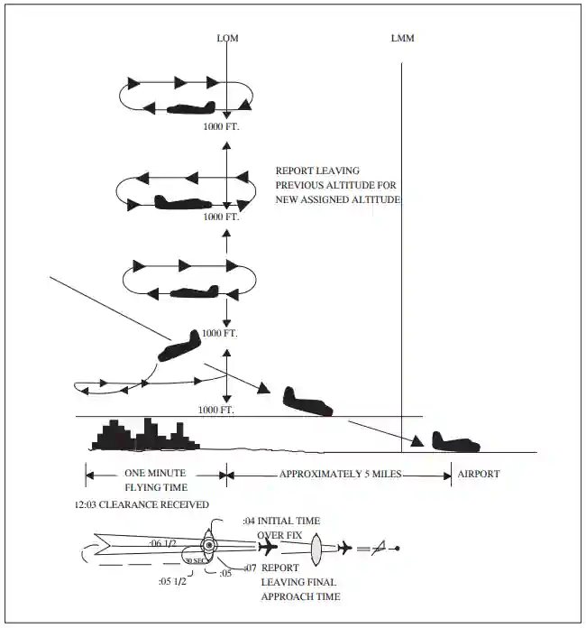
Special Instrument Approach Procedures
- Instrument Approach Procedure (IAP) charts reflect the criteria associated with the U.S. Standard for Terminal Instrument [Approach] Procedures (TERPs), which prescribes standardized methods for use in developing IAPs
- Standard IAPs are published in the Federal Register (FR) in accordance with Title 14 of the Code of Federal Regulations, Part 97, and are available for use by appropriately qualified pilots operating properly equipped and airworthy aircraft in accordance with operating rules and procedures acceptable to the FAA
- Special IAPs are also developed using TERPS but are not given public notice in the FR
- The FAA authorizes only certain individual pilots and/or pilots in individual organizations to use special IAPs, and may require additional crew training and/or aircraft equipment or performance, and may also require the use of landing aids, communications, or weather services not available for public use
- Additionally, IAPs that service private use airports or heliports are generally special IAPs
- FDC NOTAMs for Specials, FDC T-NOTAMs, may also be used to promulgate safety-of-flight information relating to Specials provided the location has a valid landing area identifier and is serviced by the United States NOTAM system
- Pilots may access NOTAMs online or through an FAA Flight Service Station (FSS)
- FSS specialists will not automatically provide NOTAM information to pilots for special IAPs during telephone pre-flight briefings
- Pilots who are authorized by the FAA to use special IAPs must specifically request FDC NOTAM information for the particular special IAP they plan to use
- Approval and use of precision approach systems other than ILS and GLS require the issuance of special instrument approach procedures
- Special instrument approach procedures must be issued to the aircraft operator if pilot training, aircraft equipment, and/or aircraft performance is different than published procedures
- Special instrument approach procedures are not distributed for general public use
- These procedures are issued to an aircraft operator when the conditions for operations approval are satisfied
- General aviation operators requesting approval for special procedures should contact the local Flight Standards District Office to obtain a letter of authorization
- Air carrier operators requesting approval for use of special procedures should contact their Certificate Holding District Office for authorization through their Operations Specification
- See also: Transponder Landing System for additional precision approach systems other than ILS and GLS
Side-Step Maneuver
- ATC may authorize a standard instrument approach procedure, which serves either one of parallel runways that are separated by 1,200' or less, followed by a straight-in landing on the adjacent runway.
- ATC will clear aircraft that plan to execute a side-step maneuver for a specified approach procedure and landing on the adjacent parallel runway.
- "Cleared ILS runway 7 left approach, side-step to runway 7 right."
- Pilots should execute side-step maneuvers as soon as possible after spotting the runway environment.
- ATC expects compliance with minimum altitudes associated with step-down fixes even after the pilot initiates the side-step maneuver.
- Side-step minima are flown to an MDA, regardless of the authorized approach.
- Published for true side-steps.
- Circling minimums if no published maneuvers.
- Landing minimums to the adjacent runway are non-precision-based and therefore higher than the precision minimums to the primary runway.
- Still, they will normally be lower than the published circling minimums.
Low Approaches
- A low approach sometimes referred to as a low pass, is essentially a go-around maneuver following an approach
- Instead of touching down, a pilot may wish to go-around without touching down in order to expedite a particular operation
- Typically performed in conjunction with a practice approach where you want to maximize fuel to shoot as many approaches as possible
- Unless authorized, the low approach should be made straight ahead, with no turns or climb made until the pilot has made a thorough visual check for other aircraft in the area
-
Towered Operations
- When operating within a Class B, Class C, and Class D surface area, a pilot intending to make a low approach should contact the tower for approval
- This request should be made prior to starting the final approach
- The aircraft will be treated as an arriving aircraft until touchdown or crossing the landing threshold
- Thereafter, the aircraft will be considered a departing aircraft
- The aircraft will be issued appropriate departure instructions following the completion of the approach
- Climb-out instructions must include a specific heading or a route of flight and altitude, except when the aircraft will maintain VFR and contact the tower
- ATC: "After completing low approach, climb and maintain six thousand Turn right, heading three six zero"
- ATC: "Maintain VFR, contact tower"
- Climb-out instructions may be omitted after the first approach if instructions remain the same
- When operating within a Class B, Class C, and Class D surface area, a pilot intending to make a low approach should contact the tower for approval
-
Non-Towered Operations
- When operating to an airport, not within a Class B, Class C, and Class D surface area, a pilot intending to make a low approach should, prior to leaving the final approach fix inbound (non-precision approach) or the outer marker or fix used in lieu of the outer marker inbound (precision approach), so advise the FSS, UNICOM, or make a broadcast as appropriate
Charted Visual Flight Procedures
- A visual approach is a procedure for a runway at an airport conducted under Instrument Flight Rules (IFR), where the pilot proceeds by visual reference and is clear of clouds to the airport.
- The Federal Aviation Administration publishes Charted Visual Flight Procedures (CVFPs) for environmental/noise considerations and/or when necessary for the safety and efficiency of air traffic operations.
- Designed primarily for turbojet aircraft.
- Located from various sources, these procedures outline what pilots should follow.
- CVFPs are not instrument approaches and do not have a Missed Approach Point (MAP).
- Unless indicating a class Bravo airspace floor, all depicted altitudes are for noise abatement purposes and recommended only.
- Pilots may fly at altitudes other than those recommended if operational requirements dictate.
- ATC may assign additional restrictions.
- CVFPs are when the Air Traffic Control (ATC) facility manager, in coordination with airport management, determines that the procedure would mitigate aircraft noise or improve safety and efficiency.
- The FAA develops a CVFP only after exhausting all PBN approach options.
-
Locating Charted Visual Approach Procedures
- The FAA publishes CVFPs online at: https://www.faa.gov/air_traffic/flight_info/aeronav/digital_products/dtpp/. []
-
Charted Visual Approach Procedure
- Depict prominent landmarks, courses, and recommended altitudes to specific runways.
- Most charts depict some Navigational Aid (NAVAID) information for supplemental navigation guidance, beginning within 20 Nautical Miles (NM) from the airport.
-
Charted Visual Approach Procedure Requirements
- There is an operating control tower.
- ATC will not issue clearances for CVFPs when the weather is less than the published minimum
- When using parallel or intersecting/converging runways, the criteria specified in JO 7110.65 (7-4-4), Approaches to Multiple Runways, are applied.
- An aircraft not following another aircraft on the approach reports sighting a charted visual landmark, or reports sighting a preceding aircraft landing on the same runway, and has been instructed to follow that aircraft.
- If instructed to follow a preceding aircraft, pilots are responsible for maintaining a safe approach interval and wake turbulence separation.
- When landmarks used for navigation are not visible at night, the approach will be annotated "procedure not authorized at night."
-
Charted Visual Approach Procedure Clearance
- ATC: "[Callsign], cleared [Approach] approach."
- Pilots should advise ATC if at any point they are unable to continue an approach or lose sight of a preceding aircraft.
- Air Traffic Control handles missed approaches as go-arounds.
- Have pre-planned climb-out options based on aircraft performance and terrain features.
- When conducting visual approaches, pilots are encouraged to use other available navigational aids to assist in positive lateral and vertical alignment with the assigned runway.
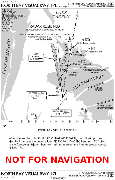
Option Approach
- Option approaches permit a pilot the option to make a touch-and-go, low approach, missed approach, stop-and-go, or full stop landing
- Use of this procedure can be very beneficial in facilitating training situations in that neither the student pilot nor examinee would know what maneuver would be accomplished
- The advantages of this procedure as a training aid are that it enables an instructor or examiner to obtain the reaction of a trainee or examinee under changing conditions, the pilot would not have to discontinue an approach in the middle of the procedure due to student error or pilot proficiency requirements, and finally it allows more flexibility and economy in training programs
- The pilot should make a request for this procedure passing the final approach fix inbound on an instrument approach or entering downwind for a VFR traffic pattern
- Pilot: "[Agency], [Callsign], [Location], request option"
- After ATC approval of the option, the pilot should inform ATC as soon as possible of any delay on the runway during their stop-and-go or full stop landing
- This procedure will only be used at those locations with an operational control tower and will be subject to ATC approval
- ATC: "Cleared for the option"
Circling Approaches
-
Final Approach Obstacle Clearance - The Federal Aviation Administration establishes circling-only approaches to give pilots additional instrument approach options, either due to weather or equipment limitations.
- Circling approaches are depicted similarly to other instrument approaches, containing circling minima only.
- Instrument approach plates will publish circling minimums where the maneuver is permitted.
- As a result, circling approach minimums require unique considerations.
- Regardless of whether flying a straight-in or circling-only approach, a circling maneuver is always required.
- Circling approaches are potentially dangerous maneuvers requiring a lot of situational awareness.
- You will be low, you will be slow, and the weather may be bad.
- You may have little time, depending on the weather minimums, to orient yourself.
- With a circling approach clearance, pilots execute the circling approach/maneuver to landing.
- With circling approaches, unique missed approach scenarios warrant special consideration.
-
Circling Approach Purpose:
- Circling-only approaches are not for any specific runway; they require a circle to maneuver in the visual segment to land.
- There are no Federal Aviation Regulations (FARs) specific to the circling maneuver.
- According to the Instrument Procedures Handbook, the FAA publishes circling-only approaches when:
- The final approach course is not within 30° of the runway heading.
- The descent gradient is greater than 400 feet per nautical mile from the final approach fix to the threshold, or;
- When the airfield layout does not clearly define the runways.
- The FAA labels circling-only approach plates with the Navigation Aid (NAVAID) and a letter (i.e., VOR-A). []
- Airports with more than one circling-only approach will increase the letter designation (i.e., VOR-A, VOR-B, etc.).
- Fundamentally, pilots fly circling-only approaches the same way they fly all other approaches.
- Circling-only approaches are not for any specific runway; they require a circle to maneuver in the visual segment to land.
-
Circling Approach Depiction:
- Instrument approach plates will publish circling minimums where the maneuver is permitted.
- Circling minimums are published at the bottom of the plate with the straight-in minimums.
- In the case of a straight-in approach where circling is permitted, straight-in and circling minimums will be published. []
- In the case of an ILS where circling is permitted, circling minimums are published, but the missed approach point is at the published missed approach point, not where the glide slope intercepts the circling minimums.
- In the case of a circling-only approach, the approach chart will publish only circling minimums (no straight-in minimums). []
- Where applicable, the pilot briefing and procedures notes section of the instrument approach plate publishes special instructions for circling. []
- To aid the pilot, the airport diagram on the instrument approach plate will have an arrow showing aircraft orientation to the airport when approaching the runway. []
- Instrument approach plates will publish circling minimums where the maneuver is permitted.
-
Circling Approach Minimums:
- Any time pilots perform a circling maneuver, regardless of whether the approach is straight-in or circling-only, circling minimums apply.
- Circling minimums are higher than other minimums because the pilot is conducting a visual approach segment.
- Published minimums will provide a 300' obstacle clearance when pilots remain within the appropriate area of protection.
- Remember when you fly the approach, if you intend to circle to, descend to the circling Minimum Descent Altitude (MDA), not the straight-in MDAs (circling is typically higher than straight-in minimums).
- If no circling minimums are published, do not execute a circle to land. However, if authorized by Air Traffic Control (ATC), basic Visual Flight Rules (1000-3) are required.
- Pilots must stay at or above the circling MDA altitude until they are continuously in a position to descend and land on the intended runway using normal maneuvers.
- Usually, being in a position to descend and land will be just inside the 180/abeam, for most circling minimums would have you low on downwind.
-
Circling Minimums for RNAV Approaches:
- Circling minimums charted on an RNAV (GPS) approach chart may be lower than the LNAV/VNAV line of minima, but never lower than the LNAV line of minima (straight-in approach). Pilots may safely perform the circling maneuver at the circling published line of minima if the approach and circling maneuver is properly performed according to aircraft category and operational limitations
- [] provides a visual representation of an obstacle evaluation and calculation of LNAV MDA, Circling MDA, LNAV/VNAV DA
-
No Vertical Guidance (LNAV):
- A line is drawn horizontal at obstacle height and 250 feet added for Required Obstacle Clearance (ROC). The controlling obstacle used to determine LNAV MDA can be different than the controlling obstacle used in determining ROC for circling MDA. Other factors may force a number larger than 250 ft to be added to the LNAV OCS. The number is rounded up to the next higher 20 foot increment
-
Circling MDA:
- The circling MDA will provide 300 foot obstacle clearance within the area considered for obstacle clearance and may be lower than the LNAV/VNAV DA, but never lower than the straight in LNAV MDA. This may occur when different controlling obstacles are used or when other controlling factors force the LNAV MDA to be higher than 250 feet above the LNAV OCS. In FIG 5-4-11, the required obstacle clearance for both the LNAV and Circle resulted in the same MDA, but lower than the LNAV/VNAV DA. FIG 5-4-12 provides an illustration of this type of situation
-
Vertical Guidance (LNAV/VNAV):
- A line is drawn horizontal at obstacle height until reaching the obstacle clearance surface (OCS). At the OCS, a vertical line is drawn until reaching the glide path. This is the DA for the approach. This method places the offending obstacle in front of the LNAV/VNAV DA so it can be seen and avoided. In some situations, this may result in the LNAV/VNAV DA being higher than the LNAV and/or Circling MDA
-
Circling Maneuver
- Pilots fly circling maneuvers in the visual segment of the instrument approach.
- Depending on the category, aircraft circle within a specified proximity from the airport to land on the desired runway.
- The circling maneuver is not part of an instrument approach; it is the follow-on action to completing a circling approach.
- Circling approaches are one of the most challenging flight maneuvers conducted in the National Airspace System, especially for pilots of Category (CAT) C and CAT D turbine-powered transport category airplanes. These maneuvers are performed at low altitude, both day and night, often with precipitation present, which affects visibility, depth perception, and the ability to assess the descent profile to the landing runway.
- Pilots must maintain a specified radius based on aircraft category when circling to land.
- If GPS distance is not available or desired, a good visual cue is to use the runway (a known distance) as a ruler.
- There are no restrictions on passing over the airport or other runways. []
-
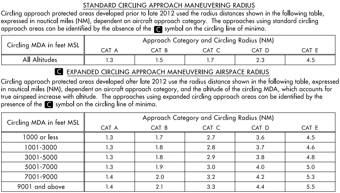
Standard and Expanded Circling Approach Radii in the U.S. TPP
-
Circling Approach Clearance
- Once under approach control, you are ready to put in your request.
- Pilot: "[Agency], [Callsign], [Location], [Information], request."
- Example: "Daytona Approach, Cessna One Seven Two Seven Victor, 10 miles to the west with information Charlie, request."
- ATC will have you "stand by" or tell you to "send your request."
- Pilot: "[Callsign], request [Approach]."
- Example: "One Seven Two Seven Victor requests LOC 7L, circle runway 16."
- ATC will inform you of what you requested or provide modified instructions.
- Expect to switch to the tower frequency when approaching the VFR traffic pattern to keep everyone on the same frequency.
- Once under tower control, reiterate the approach request to ensure they are aware of your intentions.
- Pilot: "[Tower], [Callsign], [Location], on the [Approach], request circle to land [Runway]."
- Example: "Daytona Tower, Cessna One Seven Two Seven Victor, 3 miles to the west on the LOC 7L approach, request circle to land runway 16."
- ATC will either approve you or, if unable, request you continue on your current approach for the straight-in.
- ATC: "Cleared for [Approach], circle to land [Runway]."
- Example: "Cleared for the LOC runway 7L approach, circle north to land runway 16."
- If you forget, or you think you've heard contrary to the instructions you were expecting, read back for an added idiot check.
- Pilot: "Understand circling North?"
- Once under approach control, you are ready to put in your request.
-
Circling Maneuver Procedure
WARNING:
All procedures are GENERALIZED.
Use the Pilot Operating Handbook (POH) procedures for specific aircraft performance and limitations.
and/or current Standard Operating Procedures (SOPs).
- Commence the report, start the timer as necessary.
- Maneuver on the shortest path to the base or downwind leg, as appropriate, considering existing weather conditions.
- Circling may be made in conjunction with other flight operations at the airport.
- Plan to use standard left turns to circle to land, unless ATC dictates otherwise.
- Remain within the circling visibility minima during the circling approach.
- While there is no restriction on passing over the airport or other runways, expect restrictions during training operations.
- Remain at circling minimums until continuously in a position from which a normal descent rate to a landing on the intended runway using normal maneuvering.
- When descending from circling minimums:
- Callout (over the ICS), "Runway in Sight, Landing."
- Set the power to approach the speed.
- Complete a GUMP (Gas, Undercarriage, Mixture, Prop) check.
- When appropriate, at or below VFE, set the flaps.
- Complete the appropriate landing procedure.
-
Missed Approach Considerations
- Suppose visual reference with any identifiable part of the airport is lost while circling to land from an Instrument Approach Procedure. In that case, pilots must execute a missed approach (published or dictated by ATC).
- Maintain distance limitations that are dependent on aircraft class. [/]
- Always make the initial climbing turn toward the landing runway and continue the turn until established on the missed approach course. [/]
-
Circling Approach Case Studies
- National Transportation Safety Board Identification: ANC07FA073:
- The NTSB determines the probable cause(s) of this accident to be: The pilot's failure to maintain altitude/distance from obstacles during an Instrument Flight Rules circling approach, and his inability to follow the instrument approach procedure. Contributing to the accident were clouds.
- National Transportation Safety Board Identification: NYC07FA130:
- The NTSB determines the probable cause(s) of this accident to be: The pilot's failure to maintain airspeed, which resulted in an inadvertent stall and subsequent impact with terrain.
- National Transportation Safety Board Identification: DFW07FA067:
- The NTSB determines the probable cause(s) of this accident to be: The pilot's failure to maintain clearance with terrain. Contributing factors were drizzle/mist and weather conditions below the approach/landing minimums.
- National Transportation Safety Board Identification: ATL07FA013:
- The NTSB determines the probable cause(s) of this accident to be: The pilot's failure to maintain airspeed while maneuvering with a low ceiling in instrument flight conditions, resulting in an inadvertent stall and collision with trees on the ground. Factors in the accident were the pilot's failure to follow the published missed approach procedures and the airplane's checklist procedures for a balked landing.
- National Transportation Safety Board Identification: DFW06LA073:
- The NTSB determines the probable cause(s) of this accident to be: The pilot's loss of control while on approach to the runway. Contributing factors were the downdraft and the lack of suitable terrain for the off-airport landing.
- National Transportation Safety Board Identification: ANC07FA073:
-
Circling Approaches Knowledge Quiz
-
Circling Approaches Conclusion
- Circling approaches are helpful tools for executing an approach that is well aligned with your route of flight to circle (almost in the traffic pattern) rather than fly past an airport for a straight-in.
- Circling approaches and circling maneuvers are terms that often get used interchangeably.
- Circling approaches should refer to circling-only approaches (i.e., VOR-A). In contrast, the circling maneuver should refer to circling to a runway other than the runway named by an instrument approach.
- Circling approaches are challenging maneuvers, often conducted at low altitudes, where precipitation affects visibility, depth perception, and the ability to assess the descent profile to the landing runway.
- Circling approaches are typically conducted to runways without the aid of electronic navigation systems, supporting the descent from the Circling Minimums Decision Altitude (CMDA) to the runway.
- Pilots must use sound judgment, possess an in-depth knowledge of their capabilities, and fully understand their aircraft's performance to determine the exact circling maneuver. Take into account weather, unique airport design, aircraft position, altitude, and airspeed.
- When circling, maneuver the shortest path to join the pattern, on the base or downwind leg, as appropriate, considering existing weather conditions.
- Circling maneuvers may be made while VFR or other flight operations are in progress.
- If in Class G airspace, make all turns of that airplane to the left (with the intent to follow the flow of traffic) unless the airport displays approved light signals or visual markings indicating right turns, in which case the pilot must make all turns to the right.
- If in Class E or any towered airspace, circling instructions may be provided by ATC.
- In their absence, follow the same requirements as if in class G airspace.
- You are never required to fly the MDA if out of the clouds and should fly as close to the published traffic pattern parameters as possible.
- And while circling, don't descend below MDA until the runway environment is in sight.
- See Advisory Circular 90-66C, Non-Towered Airport Flight Operations and the 2014 Krug legal interpretation letter for more information.
- At airports without a control tower, it may be desirable to fly over the airport to observe wind and turn indicators. Other traffic may be on the runway or flying in the vicinity of the airport.
- Unsafe landings follow unstabilized approaches; however, requesting an option to perform a lap in the pattern to a complete stop provides options.
- While circling approaches exist as a tool, given their complexity at low altitude in potentially low weather conditions, consider them a secondary option to conducting a straight-in approach, unless for training or out of necessity.
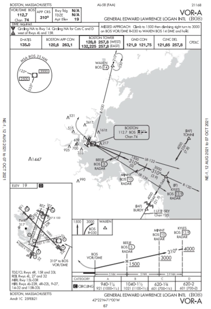
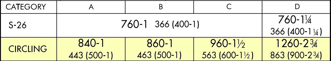


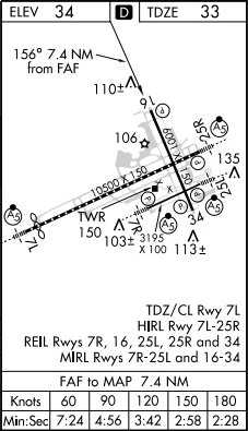


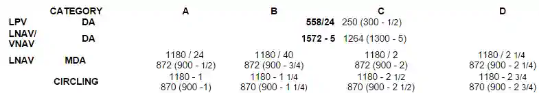
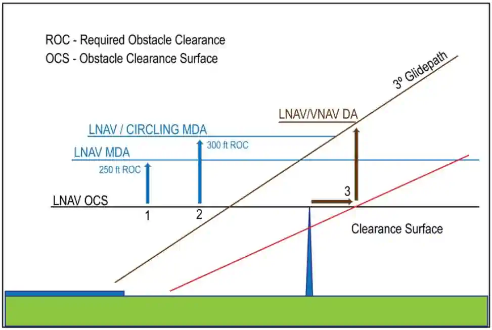

GPS Instrument Approaches
- GPS overlay approaches are designated non-precision instrument approach procedures that pilots are authorized to fly using GPS avionics
- Localizer (LOC), localizer type directional aid (LDA), and simplified directional facility (SDF) procedures are not authorized
- Overlay procedures are identified by the "name of the procedure" and "or GPS" (e.g., VOR/DME or GPS RWY 15) in the title []
- Authorized procedures must be retrievable from a current onboard navigation database
- The navigation database may also enhance position orientation by displaying a map containing information on conventional NAVAID approaches
- This approach information should not be confused with a GPS overlay approach (see the receiver operating manual, AFM, or AFM Supplement for details on how to identify these approaches in the navigation database)
- Overlay approaches do not adhere to the design criteria described in Paragraph 5-4-5m, Area Navigation (RNAV) Instrument Approach Charts, for stand-alone GPS approaches. Overlay approach criteria is based on the design criteria used for ground-based NAVAID approaches
- Stand-alone approach procedures specifically designed for GPS systems have replaced many of the original overlay approaches
- All approaches that contain "GPS" in the title (e.g., "VOR or GPS RWY 24," "GPS RWY 24," or "RNAV (GPS) RWY 24") can be flown using GPS
- GPS-equipped aircraft do not need underlying ground-based NAVAIDs or associated aircraft avionics to fly the approach
- Monitoring the underlying approach with ground-based NAVAIDs is suggested when able
- Existing overlay approaches may be requested using the GPS title; for example, the VOR or GPS RWY 24 may be requested as "GPS RWY 24"
- Some GPS procedures have a Terminal Arrival Area (TAA) with an underlining RNAV approach
- For flight planning purposes, TSOC129() and TSOC196()-equipped users (GPS users) whose navigation systems have fault detection and exclusion (FDE) capability, who perform a preflight RAIM prediction for the approach integrity at the airport where the RNAV (GPS) approach will be flown, and have proper knowledge and any required training and/or approval to conduct a GPSbased IAP, may file based on a GPS-based IAP at either the destination or the alternate airport, but not at both locations
- At the alternate airport, pilots may plan for:
- Lateral navigation (LNAV) or circling minimum descent altitude (MDA);
- LNAV/vertical navigation (LNAV/VNAV) DA, if equipped with and using approved barometric vertical navigation (baroVNAV) equipment;
- RNP 0.3 DA on an RNAV (RNP) IAP, if they are specifically authorized users using approved baroVNAV equipment and the pilot has verified required navigation performance (RNP) availability through an approved prediction program
- If the above conditions cannot be met, any required alternate airport must have an approved instrument approach procedure other than GPS-based that is anticipated to be operational and available at the estimated time of arrival, and which the aircraft is equipped to fly
-
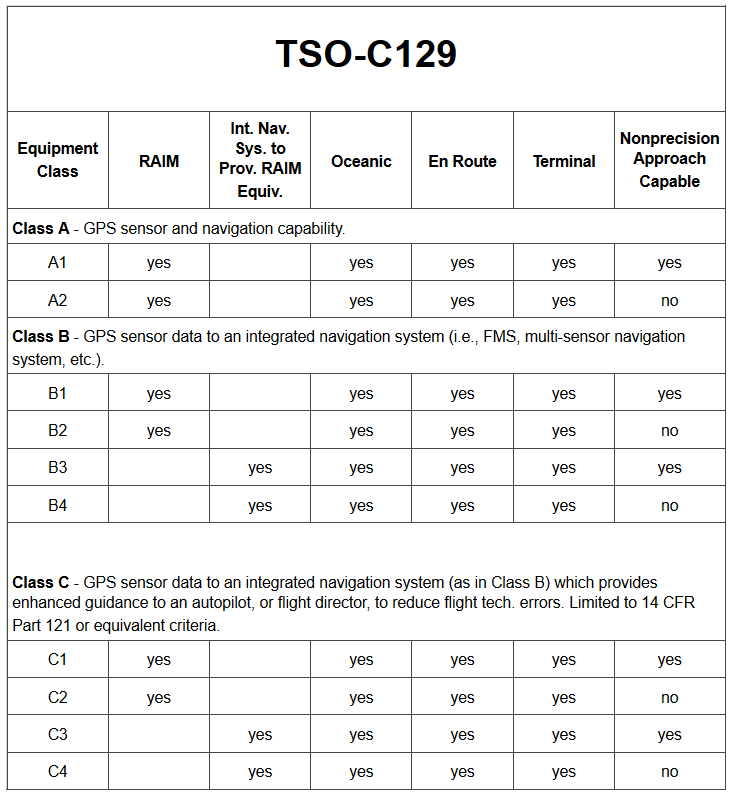
GPS IFR Equipment Classes/Categories -
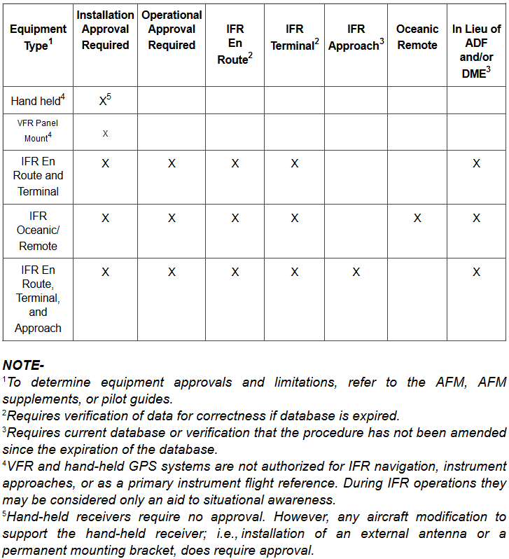
GPS Approval Required/Authorized Use -
Terminal Arrival Area
- The Terminal Arrival Area (TAA) provides a transition from the en-route structure to the terminal environment with little required pilot/air traffic control interface for aircraft equipped with Area Navigation (RNAV) systems.
- A TAA provides minimum altitudes with standard obstacle clearance when operating within the TAA boundaries.
- TAAs are primarily used on RNAV approaches but may be used on an ILS approach when RNAV is the sole means for navigation to the IF; however, they are not normally used in areas of heavy concentration of air traffic.
- The basic design of the RNAV procedure underlying the TAA is normally the "T" design (also called the "Basic T").
- The "T" design incorporates two IAFs plus a dual purpose IF/IAF that functions as both an intermediate fix and an initial approach fix.
- The T configuration continues from the IF/IAF to the final approach fix (FAF) and then to the missed approach point (MAP).
- The two base leg IAFs are typically aligned in a straight-line perpendicular to the intermediate course connecting at the IF/IAF.
- A Hold-in-Lieu-of Procedure Turn (HILPT) is anchored at the IF/IAF and depicted on U.S. Government publications using the "hold-in-lieu -of-PT" holding pattern symbol.
- When the HILPT is necessary for course alignment and/or descent, the dual purpose IF/IAF serves as an IAF during the entry into the pattern.
- Following entry into the HILPT pattern and when flying a route or sector labeled "NoPT," the dual-purpose fix serves as an IF, marking the beginning of the Intermediate Segment. [/]
- The standard TAA based on the "T" design consists of three areas defined by the Initial Approach Fix (IAF) legs and the intermediate segment course beginning at the IF/IAF.
- These areas are called the straight-in, left-base, and right-base areas. [Figure x]
- TAA area lateral boundaries are identified by magnetic courses TO the IF/IAF.
- The straight-in area can be further divided into pie- shaped sectors with the boundaries identified by magnetic courses TO the (IF/ IAF), and may contain stepdown sections defined by arcs based on RNAV distances from the IF/IAF. [Figure x]
- The right/left-base areas can only be subdivided using arcs based on RNAV distances from the IAFs for those areas.
- Entry from the terminal area onto the procedure is normally accomplished via a no procedure turn (NoPT) routing or via a course reversal maneuver.
- The published procedure will be annotated "NoPT" to indicate when the course reversal is not authorized when flying within a particular TAA sector.
- Otherwise, the pilot is expected to execute the course reversal under the provisions of 14 CFR Section 91.175.
- The pilot may elect to use the course reversal pattern when it is not required by the procedure, but must receive clearance from air traffic control before beginning the procedure.
- ATC should not clear an aircraft to the left base leg or right base leg IAF within a TAA at an intercept angle exceeding 90°. Pilots must not execute the HILPT course reversal when the sector or procedure segment is labeled "NoPT."
- ATC may clear aircraft direct to the fix labeled IF/IAF if the course to the IF/IAF is within the straight-in sector labeled "NoPT" and the intercept angle does not exceed 90°.
- Pilots are expected to proceed direct to the IF/IAF and accomplish a straight-in approach.
- Do not execute HILPT course reversal.
- Pilots are also expected to fly the straight-in approach when ATC provides radar vectors and monitoring to the IF/IAF and issues a "straight-in" approach clearance; otherwise, the pilot is expected to execute the HILPT course reversal.
- Reference-AIM, Paragraph 5-4-6, Approach Clearance
- On rare occasions, ATC may clear the aircraft for an approach at the airport without specifying the approach procedure by name or by a specific approach (for example, "cleared RNAV Runway 34 approach") without specifying a particular IAF.
- In either case, the pilot should proceed direct to the IAF or to the IF/IAF associated with the sector that the aircraft will enter the TAA and join the approach course from that point and if required by that sector (i.e., sector is not labeled "NoPT"), complete the HILPT course reversal.
- If approaching with a TO bearing that is on a sector boundary, the pilot is expected to proceed in accordance with a "NoPT" routing unless otherwise instructed by ATC.
- In either case, the pilot should proceed direct to the IAF or to the IF/IAF associated with the sector that the aircraft will enter the TAA and join the approach course from that point and if required by that sector (i.e., sector is not labeled "NoPT"), complete the HILPT course reversal.
- Altitudes published within the TAA replace the MSA altitude (and provide the same obstruction clearance).
- However, unlike MSA altitudes the TAA altitudes are operationally usable altitudes.
- It is important that the pilot knows which area of the TAA the aircraft will enter in order to comply with the minimum altitude requirements. The pilot can determine which area of the TAA the aircraft will enter by determining the magnetic bearing of the aircraft TO the fix labeled IF/IAF. The bearing should then be compared to the published lateral boundary bearings that define the TAA areas. Do not use magnetic bearing to the right-base or left-base IAFs to determine position
- An ATC clearance direct to an IAF or to the IF/IAF without an approach clearance does not authorize a pilot to descend to a lower TAA altitude
- If a pilot desires a lower altitude without an approach clearance, request the lower TAA altitude from ATC
- Pilots not sure of the clearance should confirm their clearance with ATC or request a specific clearance
- Pilots entering the TAA with two−way radio communications failure (14 CFR section 91.185, IFR Operations: Two−way Radio Communications Failure), must maintain the highest altitude prescribed by section 91.185(c)(2) until arriving at the appropriate IAF
- Once cleared for the approach, pilots may descend in the TAA sector to the minimum altitude depicted within the defined area/subdivision, unless instructed otherwise by air traffic control
- If flying on an airway already, the TAA does not apply
- When ATC clears the pilot for the approach without specifying altitude, the pilot may descent to lowest appropriate MEA
- Pilots should plan their descent within the TAA to permit a normal descent from the IF/IAF to the FAF
- Pilots within the left or right-base areas are expected to maintain a minimum altitude of 6,000 feet until within 17 NM of the associated IAF []
- After crossing the 17 NM arc, descent is authorized to the lower charted altitudes
- Pilots approaching from the northwest are expected to maintain a minimum altitude of 6,000 feet, and when within 22 NM of the IF/IAF, descend to a minimum altitude of 2,000 feet MSL until crossing the IF/IAF
- U.S. Government charts depict TAAs using icons located in the plan view outside the depiction of the actual approach procedure. Use of icons is necessary to avoid obscuring any portion of the "T" procedure (altitudes, courses, minimum altitudes, etc.). The icon for each TAA area will be located and oriented on the plan view with respect to the direction of arrival to the approach procedure, and will show all TAA minimum altitudes and sector/radius subdivisions. The IAF for each area of the TAA is included on the icon where it appears on the approach to help the pilot orient the icon to the approach procedure. The IAF name and the distance of the TAA area boundary from the IAF are included on the outside arc of the TAA area icon []
-
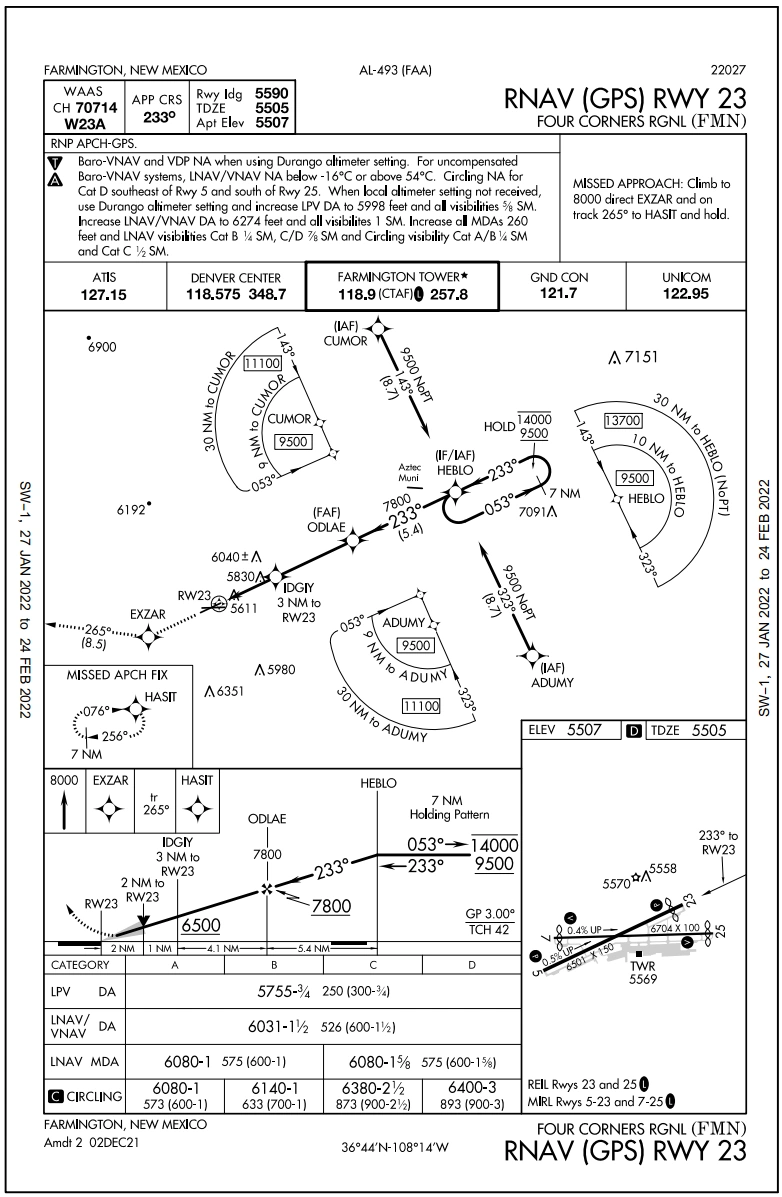
RNAV (GPS) Approach Chart - TAAs may be modified from the standard size and shape to accommodate operational or ATC requirements. Some areas may be eliminated, while the other areas are expanded. The "T" design may be modified by the procedure designers where required by terrain or ATC considerations. For instance, the "T" design may appear more like a regularly or irregularly shaped "Y," upside down "L," or an "I"
- [] depicts a TAA without a left base leg and right base leg. In this generalized example, pilots approaching on a bearing TO the IF/IAF from 271 clockwise to 089 are expected to execute a course reversal because the amount of turn required at the IF/IAF exceeds 90 degrees. The term "NoPT" will be annotated on the boundary of the TAA icon for the other portion of the TAA
-
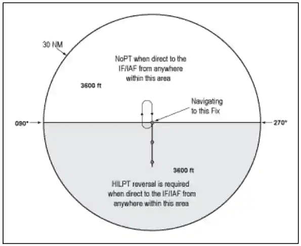
TAA with Left and Right Base Areas Eliminated - [] depicts another TAA modification that pilots may encounter. In this generalized example, the left base area and part of the straight-in area have been eliminated. Pilots operating within the TAA between 210 clockwise to 360 bearing TO the IF/IAF are expected to proceed direct to the IF/IAF and then execute the course reversal in order to properly align the aircraft for entry onto the intermediate segment or to avoid an excessive descent rate. Aircraft operating in areas from 001 clockwise to 090 bearing TO the IF/IAF are expected to proceed direct to the right base IAF and not execute course reversal maneuver. Aircraft cleared direct the IF/IAF by ATC in this sector will be expected to accomplish HILTP. Aircraft operating in areas 091 clockwise to 209 bearing TO the IF/IAF are expected to proceed direct to the IF/IAF and not execute the course reversal. These two areas are annotated "NoPT" at the TAA boundary of the icon in these areas when displayed on the approach chart's plan view
-
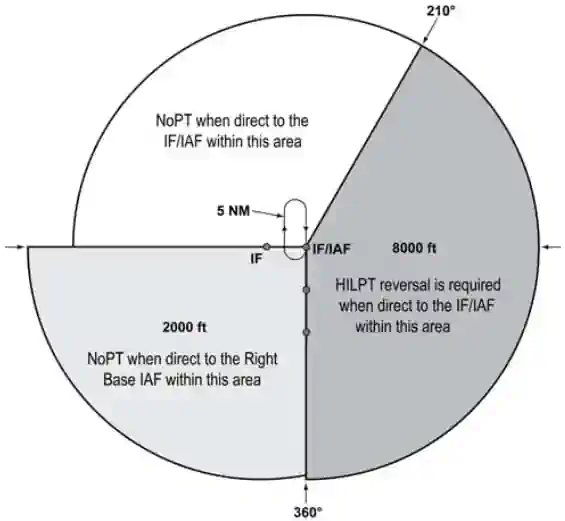
TAA with Left Base and Part of Straight-In Area Eliminated - [] depicts a TAA with right base leg and part of the straight-in area eliminated
-
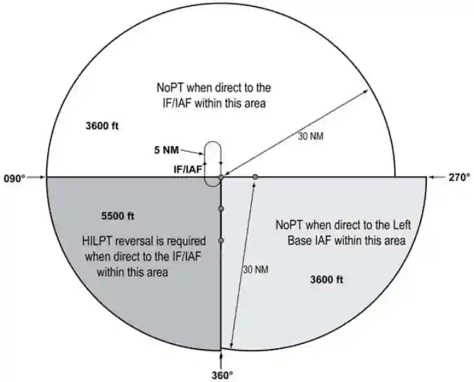
TAA with Right Base Eliminated - When an airway does not cross the lateral TAA boundaries, a feeder route will be established from an airway fix or NAVAID to the TAA boundary to provide a transition from the en route structure to the appropriate IAF. Each feeder route will terminate at the TAA boundary and will be aligned along a path pointing to the associated IAF. Pilots should descend to the TAA altitude after crossing the TAA boundary and cleared for the approach by ATC []
- Each waypoint on the "T" is assigned a pronounceable 5-letter name, except the missed approach waypoint. These names are used for ATC communications, RNAV databases, and aeronautical navigation products. The missed approach waypoint is assigned a pronounceable name when it is not located at the runway threshold
-
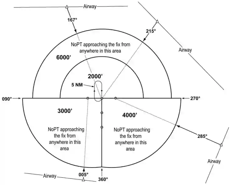
Examples of a TAA with Feeders from an Airway
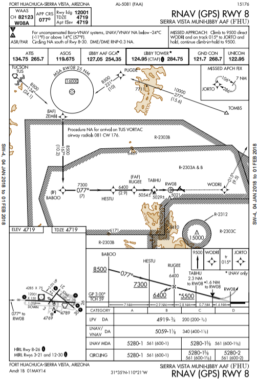
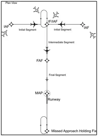
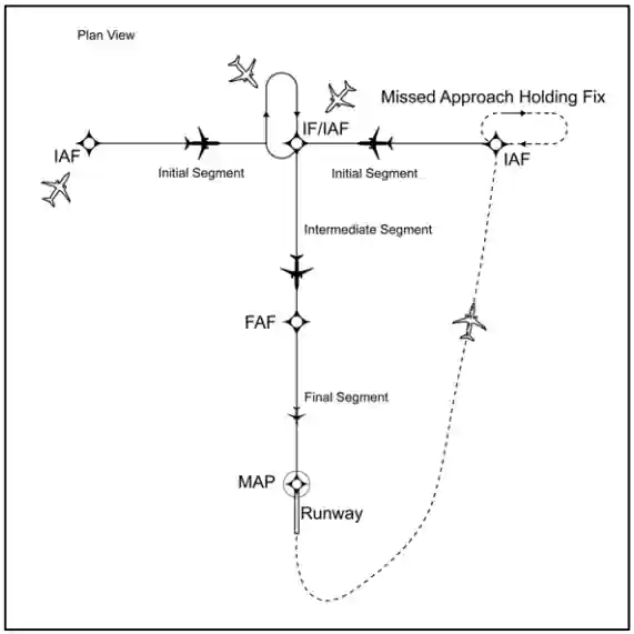
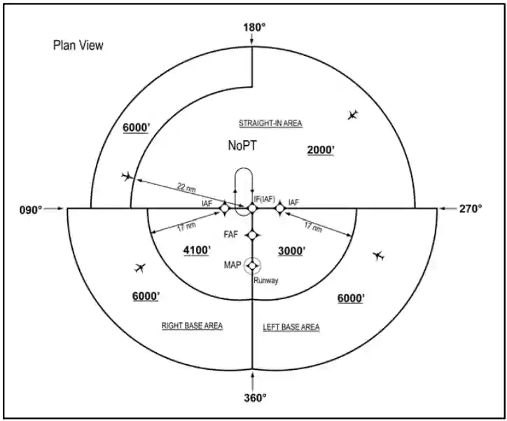
Procedures for Accomplishing GPS Approaches
- An RNAV (GPS) procedure may be associated with a Terminal Arrival Area (TAA)
- The basic design of the RNAV procedure is the "T" design or a modification of the "T" (See Paragraph 5-4-5d, Terminal Arrival Area (TAA), for complete information)
- Pilots cleared by ATC for an RNAV (GPS) approach should fly the full approach from an Initial Approach Waypoint (IAWP) or feeder fix
- Randomly joining an approach at an intermediate fix does not assure terrain clearance
- When an approach has been loaded in the navigation system, GPS receivers will give an "arm" annunciation 30 NM straight line distance from the airport/heliport reference point
- Pilots should arm the approach mode at this time if not already armed (some receivers arm automatically)
- Without arming, the receiver will not change from en-route CDI and RAIM sensitivity of ±5 NM either side of centerline to ±1 NM terminal sensitivity
- Where the IAWP is inside this 30 mile point, a CDI sensitivity change will occur once the approach mode is armed and the aircraft is inside 30 NM
- Where the IAWP is beyond 30 NM from the airport/heliport reference point and the approach is armed, the CDI sensitivity will not change until the aircraft is within 30 miles of the airport/heliport reference point
- Feeder route obstacle clearance is predicated on the receiver being in terminal (±1 NM) CDI sensitivity and RAIM within 30 NM of the airport/heliport reference point; therefore, the receiver should always be armed (if required) not later than the 30 NM annunciation
- The pilot must be aware of what bank angle/turn rate the particular receiver uses to compute turn anticipation, and whether wind and airspeed are included in the receiver's calculations
- This information should be in the receiver operating manual
- Over or under banking the turn onto the final approach course may significantly delay getting on course and may result in high descent rates to achieve the next segment altitude
- When within 2 NM of the Final Approach Waypoint (FAWP) with the approach mode armed, the approach mode will switch to active, which results in RAIM and CDI changing to approach sensitivity
- Beginning 2 NM prior to the FAWP, the full scale CDI sensitivity will smoothly change from ±1 NM to ±0.3 NM at the FAWP
- As sensitivity changes from ±1 NM to ±0.3 NM approaching the FAWP, with the CDI not centered, the corresponding increase in CDI displacement may give the impression that the aircraft is moving further away from the intended course even though it is on an acceptable intercept heading
- Referencing the digital track displacement information (cross track error), if it is available in the approach mode, may help the pilot remain position oriented in this situation
- Being established on the final approach course prior to the beginning of the sensitivity change at 2 NM will help prevent problems in interpreting the CDI display during ramp down
- Therefore, requesting or accepting vectors which will cause the aircraft to intercept the final approach course within 2 NM of the FAWP is not recommended
- When receiving vectors to final, most receiver operating manuals suggest placing the receiver in the non-sequencing mode on the FAWP and manually setting the course
- This provides an extended final approach course in cases where the aircraft is vectored onto the final approach course outside of any existing segment which is aligned with the runway
- Assigned altitudes must be maintained until established on a published segment of the approach. Required altitudes at waypoints outside the FAWP or stepdown fixes must be considered
- Calculating the distance to the FAWP may be required in order to descend at the proper location
- Overriding an automatically selected sensitivity during an approach will cancel the approach mode annunciation
- If the approach mode is not armed by 2 NM prior to the FAWP, the approach mode will not become active at 2 NM prior to the FAWP, and the equipment will flag
- In these conditions, the RAIM and CDI sensitivity will not ramp down, and the pilot should not descend to MDA, but fly to the MAWP and execute a missed approach
- The approach active annunciator and/or the receiver should be checked to ensure the approach mode is active prior to the FAWP
- Do not attempt to fly an approach unless the procedure in the onboard database is current and identified as "GPS" on the approach chart
- The navigation database may contain information about non-overlay approach procedures that enhances position orientation generally by providing a map, while flying these approaches using conventional NAVAIDs
- This approach information should not be confused with a GPS overlay approach (see the receiver operating manual, AFM, or AFM Supplement for details on how to identify these procedures in the navigation database)
- Flying point to point on the approach does not assure compliance with the published approach procedure
- The proper RAIM sensitivity will not be available and the CDI sensitivity will not automatically change to ±0.3 NM
- Manually setting CDI sensitivity does not automatically change the RAIM sensitivity on some receivers
- Some existing non-precision approach procedures cannot be coded for use with GPS and will not be available as overlays
- Pilots should pay particular attention to the exact operation of their GPS receivers for performing holding patterns and in the case of overlay approaches, operations such as procedure turns
- These procedures may require manual intervention by the pilot to stop the sequencing of waypoints by the receiver and to resume automatic GPS navigation sequencing once the maneuver is complete
- The same waypoint may appear in the route of flight more than once consecutively (for example, IAWP, FAWP, MAHWP on a procedure turn)
- Care must be exercised to ensure that the receiver is sequenced to the appropriate waypoint for the segment of the procedure being flown, especially if one or more fly-overs are skipped (for example, FAWP rather than IAWP if the procedure turn is not flown)
- The pilot may have to sequence past one or more fly-overs of the same waypoint in order to start GPS automatic sequencing at the proper place in the sequence of waypoints
- Incorrect inputs into the GPS receiver are especially critical during approaches
- In some cases, an incorrect entry can cause the receiver to leave the approach mode
- A fix on an overlay approach identified by a DME fix will not be in the waypoint sequence on the GPS receiver unless there is a published name assigned to it
- When a name is assigned, the along track distance (ATD) to the waypoint may be zero rather than the DME stated on the approach chart
- The pilot should be alert for this on any overlay procedure where the original approach used DME
- If a visual descent point (VDP) is published, it will not be included in the sequence of waypoints
- Pilots are expected to use normal piloting techniques for beginning the visual descent, such as ATD
- Unnamed stepdown fixes in the final approach segment may or may not be coded in the waypoint sequence of the aircraft's navigation database and must be identified using ATD
- Stepdown fixes in the final approach segment of RNAV (GPS) approaches are being named, in addition to being identified by ATD
- However, GPS avionics may or may not accommodate waypoints between the FAF and MAP
- Pilots must know the capabilities of their GPS equipment and continue to identify stepdown fixes using ATD when necessary
Missed Approach
- A GPS missed approach requires pilot action to sequence the receiver past the MAWP to the missed approach portion of the procedure
- The pilot must be thoroughly familiar with the activation procedure for the particular GPS receiver installed in the aircraft and must initiate appropriate action after the MAWP
- Activating the missed approach prior to the MAWP will cause CDI sensitivity to immediately change to terminal (±1NM) sensitivity and the receiver will continue to navigate to the MAWP
- The receiver will not sequence past the MAWP
- Turns should not begin prior to the MAWP
- If the missed approach is not activated, the GPS receiver will display an extension of the inbound final approach course and the ATD will increase from the MAWP until it is manually sequenced after crossing the MAWP
- Missed approach routings in which the first track is via a course rather than direct to the next waypoint require additional action by the pilot to set the course
- Being familiar with all of the inputs required is especially critical during this phase of flight
Receiver Autonomous Integrity Monitoring (RAIM)
- RAIM outages may occur due to an insufficient number of satellites or due to unsuitable satellite geometry which causes the error in the position solution to become too large
- Loss of satellite reception and RAIM warnings may occur due to aircraft dynamics (changes in pitch or bank angle)
- Antenna location on the aircraft, satellite position relative to the horizon, and aircraft attitude may affect reception of one or more satellites
- Since the relative positions of the satellites are constantly changing, prior experience with the airport does not guarantee reception at all times, and RAIM availability should always be checked
- Civilian pilots may obtain GPS RAIM availability information for nonprecision approach procedures by using a manufacturer-supplied RAIM prediction tool, or using the Service Availability Prediction Tool (SAPT) on the FAA en route and terminal RAIM prediction website
- Pilots can also request GPS RAIM aeronautical information from a flight service station during preflight briefings
- GPS RAIM aeronautical information can be obtained for a period of 3 hours (for example, if you are scheduled to arrive at 1215 hours, then the GPS RAIM information is available from 1100 to 1400 hours) or a 24-hour timeframe at a particular airport
- FAA briefers will provide RAIM information for a period of 1 hour before to 1 hour after the ETA hour, unless a specific timeframe is requested by the pilot
- If flying a published GPS departure, a RAIM prediction should also be requested for the departure airport
- The military provides airfield specific GPS RAIM NOTAMs for nonprecision approach procedures at military airfields
- The RAIM outages are issued as M-series NOTAMs and may be obtained for up to 24 hours from the time of request
- Receiver manufacturers and/or database suppliers may supply "NOTAM" type information concerning database errors
- Pilots should check these sources when available, to ensure that they have the most current information concerning their electronic database
- If RAIM is not available, use another type of navigation and approach system; select another route or destination; or delay the trip until RAIM is predicted to be available on arrival
- On longer flights, pilots should consider rechecking the RAIM prediction for the destination during the flight
- This may provide an early indication that an unscheduled satellite outage has occurred since takeoff
- If a RAIM failure/status annunciation occurs prior to the final approach waypoint (FAWP), the approach should not be completed since GPS no longer provides the required integrity
- The receiver performs a RAIM prediction by 2 NM prior to the FAWP to ensure that RAIM is available as a condition for entering the approach mode
- The pilot should ensure the receiver has sequenced from "Armed" to "Approach" prior to the FAWP (normally occurs 2 NM prior)
- Failure to sequence may be an indication of the detection of a satellite anomaly, failure to arm the receiver (if required), or other problems which preclude flying the approach
- If the receiver does not sequence into the approach mode or a RAIM failure/status annunciation occurs prior to the FAWP, the pilot must not initiate the approach nor descend, but instead, proceed to the missed approach waypoint (MAWP) via the FAWP, perform a missed approach, and contact ATC as soon as practical
- The GPS receiver may continue to operate after a RAIM flag/status annunciation appears, but the navigation information should be considered advisory only
- Refer to the receiver operating manual for specific indications and instructions associated with loss of RAIM prior to the FAF
- If the RAIM flag/status annunciation appears after the FAWP, the pilot should initiate a climb and execute the missed approach
- The GPS receiver may continue to operate after a RAIM flag/status annunciation appears, but the navigation information should be considered advisory only
- Refer to the receiver operating manual for operating mode information during a RAIM annunciation
GPS Waypoints
- GPS receivers navigate from one defined point to another retrieved from the aircraft's onboard navigational database
- These points are waypoints (5-letter pronounceable name), existing VHF intersections, DME fixes with 5-letter pronounceable names and 3-letter NAVAID IDs
- Each waypoint is a geographical location defined by a latitude/longitude geographic coordinate
- These 5-letter waypoints, VHF intersections, 5-letter pronounceable DME fixes and 3-letter NAVAID IDs are published on various FAA aeronautical navigation products (IFR Enroute Charts, VFR Charts, Terminal Procedures Publications, etc.)
- A Computer Navigation Fix (CNF) is also a point defined by a latitude/longitude coordinate and is required to support Performance-Based Navigation (PBN) operations
- The GPS receiver uses CNFs in conjunction with waypoints to navigate from point to point
- However, CNFs are not recognized by ATC. ATC does not maintain CNFs in their database and they do not use CNFs for any air traffic control purpose
- CNFs may or may not be charted on FAA aeronautical navigation products, are listed in the chart legends, and are for advisory purposes only
- Pilots are not to use CNFs for point to point navigation (proceed direct), filing a flight plan, or in aircraft/ATC communications
- CNFs that do appear on aeronautical charts allow pilots increased situational awareness by identifying points in the aircraft database route of flight with points on the aeronautical chart
- CNFs are random five-letter identifiers, not pronounceable like waypoints and placed in parenthesis
- Eventually, all CNFs will begin with the letters "CF" followed by three consonants (for example, CFWBG)
- This five-letter identifier will be found next to an "x" on enroute charts and possibly on an approach chart
- On instrument approach procedures (charts) in the terminal procedures publication, CNFs may represent unnamed DME fixes, beginning and ending points of DME arcs, and sensor (ground-based signal i.e., VOR, NDB, ILS) final approach fixes on GPS overlay approaches
- These CNFs provide the GPS with points on the procedure that allow the overlay approach to mirror the ground-based sensor approach
- These points should only be used by the GPS system for navigation and should not be used by pilots for any other purpose on the approach
- The CNF concept has not been adopted or recognized by the International Civil Aviation Organization (ICAO)
- GPS approaches use fly-over and fly-by waypoints to join route segments on an approach
- Fly-by waypoints connect the two segments by allowing the aircraft to turn prior to the current waypoint in order to roll out on course to the next waypoint
- This is known as turn anticipation and is compensated for in the airspace and terrain clearances
- The missed approach waypoint (MAWP) will always be a fly-over waypoint
- A holding waypoint will always be designed as a fly-over waypoint in the navigational database but may be charted as a fly-by event unless the holding waypoint is used for another purpose in the procedure and both events require the waypoint to be a fly-over event
- Some waypoints may have dual use; for example, as a fly-by waypoint when used as an IF for a NoPT route and as a fly-over waypoint when the same waypoint is also used as an IAF/IF hold-in-lieu of PT
- Since the waypoint can only be charted one way, when this situation occurs, the fly-by waypoint symbol will be charted in all uses of the waypoint
- Unnamed waypoints for each airport will be uniquely identified in the database
- Although the identifier may be used at different airports (for example, RW36 will be the identifier at each airport with a runway 36), the actual point, at each airport, is defined by a specific latitude/longitude coordinate
- The runway threshold waypoint, normally the MAWP, may have a five-letter identifier (for example, SNEEZ) or be coded as RW## (for example, RW36, RW36L)
- MAWPs located at the runway threshold are being changed to the RW## identifier, while MAWPs not located at the threshold will have a five-letter identifier
- This may cause the approach chart to differ from the aircraft database until all changes are complete
- The runway threshold waypoint is also used as the center of the Minimum Safe Altitude (MSA) on most GPS approaches
-
Position Orientation:
- Pilots should pay particular attention to position orientation while using GPS
- Distance and track information are provided to the next active waypoint, not to a fixed navigation aid
- Receivers may sequence when the pilot is not flying along an active route, such as when being vectored or deviating for weather, due to the proximity to another waypoint in the route
- This can be prevented by placing the receiver in the non-sequencing mode
- When the receiver is in the non-sequencing mode, bearing and distance are provided to the selected waypoint and the receiver will not sequence to the next waypoint in the route until placed back in the auto sequence mode or the pilot selects a different waypoint
- The pilot may have to compute the ATD to stepdown fixes and other points on overlay approaches, due to the receiver showing ATD to the next waypoint rather than DME to the VOR or ILS ground station
-
Impact of Magnetic Variation on PBN Systems:
- Differences may exist between PBN systems and the charted magnetic courses on ground-based NAVAID instrument flight procedures (IFP), enroute charts, approach charts, and Standard Instrument Departure/Standard Terminal Arrival (SID/STAR) charts. These differences are due to the magnetic variance used to calculate the magnetic course. Every leg of an instrument procedure is first computed along a desired ground track with reference to true north. A magnetic variation correction is then applied to the true course in order to calculate a magnetic course for publication. The type of procedure will determine what magnetic variation value is added to the true course. A ground-based NAVAID IFP applies the facility magnetic variation of record to the true course to get the charted magnetic course. Magnetic courses on PBN procedures are calculated two different ways. SID/STAR procedures use the airport magnetic variation of record, while IFR enroute charts use magnetic reference bearing. PBN systems make a correction to true north by adding a magnetic variation calculated with an algorithm based on aircraft position, or by adding the magnetic variation coded in their navigational database. This may result in the PBN system and the procedure designer using a different magnetic variation, which causes the magnetic course displayed by the PBN system and the magnetic course charted on the IFP plate to be different. It is important to understand, however, that PBN systems, (with the exception of VOR/DME RNAV equipment) navigate by reference to true north and display magnetic course only for pilot reference. As such, a properly functioning PBN system, containing a current and accurate navigational database, should fly the correct ground track for any loaded instrument procedure, despite differences in displayed magnetic course that may be attributed to magnetic variation application. Should significant differences between the approach chart and the PBN system avionics' application of the navigation database arise, the published approach chart, supplemented by NOTAMs, holds precedence
- The course into a waypoint may not always be 180 degrees different from the course leaving the previous waypoint, due to the PBN system avionics' computation of geodesic paths, distance between waypoints, and differences in magnetic variation application. Variations in distances may also occur since PBN system distance-to-waypoint values are ATDs computed to the next waypoint and the DME values published on underlying procedures are slant-range distances measured to the station. This difference increases with aircraft altitude and proximity to the NAVAID
-
GPS Familiarization:
- Pilots should practice GPS approaches in visual meteorological conditions (VMC) until thoroughly proficient with all aspects of their equipment prior to attempting flight in instrument meteorological conditions (IMC)
- Pilots should be proficient in the following areas:
- Using the receiver autonomous integrity monitoring (RAIM) prediction function;
- Inserting a DP into the flight plan, including setting terminal CDI sensitivity, if required, and the conditions under which terminal RAIM is available for departure;
- Programming the destination airport;
- Programming and flying the approaches (especially procedure turns and arcs);
- Changing to another approach after selecting an approach;
- Programming and flying "direct" missed approaches;
- Programming and flying "routed" missed approaches;
- Entering, flying, and exiting holding patterns, particularly on approaches with a second waypoint in the holding pattern;
- Programming and flying a "route" from a holding pattern;
- Programming and flying an approach with radar vectors to the intermediate segment;
- Indication of the actions required for RAIM failure both before and after the FAWP; and
- Programming a radial and distance from a VOR (often used in departure instructions)
GPS Approach Considerations
- Know your equipment, its operation, and limitations
- If cleared to an approach fix not loaded into the system, consider requesting vectors if more time to load is needed
- Load the expected approach as soon as possible to alleviate work later
- If the approach changes later, you still have time to correct
- Compare approach plate to system load, to include the use of any holds
- If receiving vectors, activate vectors to finals
- If stepdown fixes are eliminated by selecting vectors to final, consider not activating vectors and instead activating the specific leg of the approach
- Verify the CDI source is set to the appropriate system
- Monitor the annunicators to verify as expected
Conclusion
- Pilots can visit the FAA's Instrument Flight Procedures Information Gateway to review and submit questions related to the how and why certain procedures are as they are
- Still looking for something? Continue searching:
Missed Approaches
- When a landing cannot be accomplished, following an instrument approach, pilots execute what is called the missed approach procedure
- Executed once the missed approach consitions have been met, pilots are expected to fly in accordance with their missed approach clearance.
- Compliance with instructions will ensure obstacle clearance.
- It is important that both pilots and air traffic control understand their responsibilities to avoid making common errors.
-
Missed Approach Procedure Depiction
-
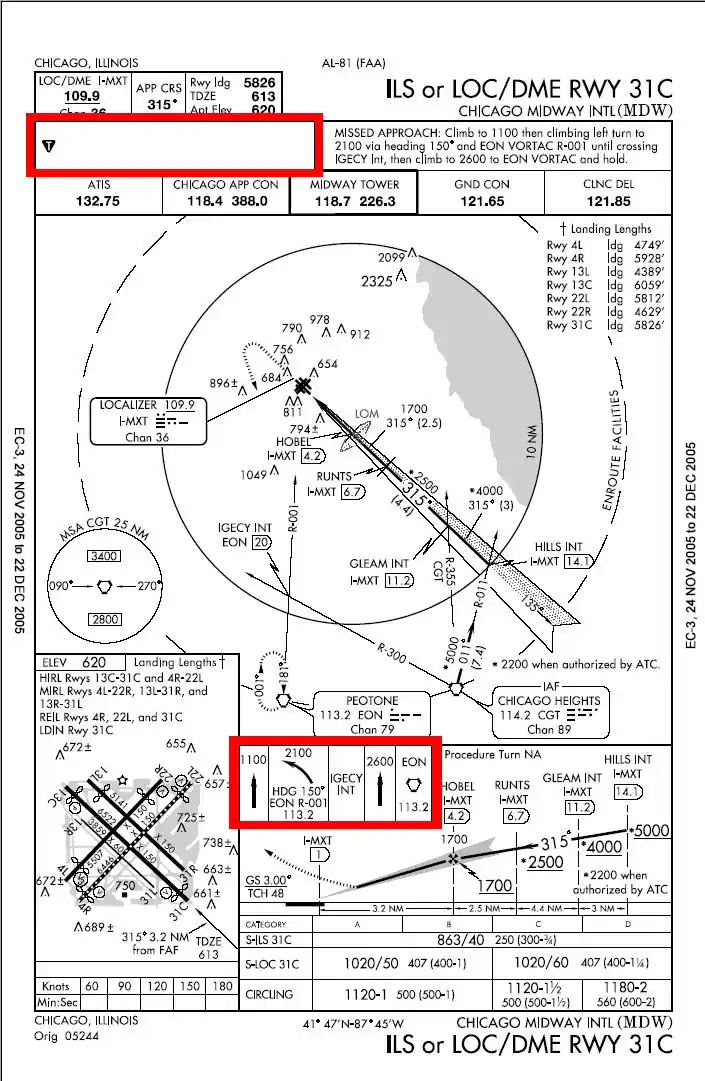
Published Missed Approach Instructions - Missed approaches are depicted on instrument approach charts in textual and graphical formats
-
Profile View Missed Approach Symbology:
- To make missed approach guidance more readily understood, a method has been developed to display missed approach guidance in the profile view through the use of quick reference icons
- Due to limited space in the profile area, only four or fewer icons can be shown
- However, the icons may not provide representation of the entire missed approach procedure
- The entire set of textual missed approach instructions are provided at the top of the approach chart in the pilot briefing []
-
-
-
Missed Approach Conditions
- Pilots shall go missed if any of the following criteria are met:
- Upon arrival at the Missed Approach Point (MAP) or Decision Height (DH), visual reference to the runway environment is insufficient to complete the landing
- Runway environment, is defined in FAR 91.175.
- A safe approach or landing is not possible
- ATC instructs you to
- When the aircraft is being operated below MDA
- Upon arrival at the Missed Approach Point (MAP) or Decision Height (DH), visual reference to the runway environment is insufficient to complete the landing
- Additionally, missed approach procedures may be executed for:
- Training
- Instrument failure
- Other emergency
- Pilots shall go missed if any of the following criteria are met:
-
Missed Approach Clearance
- Missed approach instructions can comes from two sources:
- Formal, as published on the instrument approach chart
- Verbally, given from ATC
-
Published Missed Approaches:
- A clearance for an instrument approach procedure implicitly includes a clearance to fly the published missed approach procedure, unless otherwise instructed by ATC
- Instructions are visually depicted on the profile view section of the approach plate while amplifying instructions will appear in the Pilot Briefing and Procedure Notes section []
- A dashed line on the plan view further helps the pilot visualize where they are going and where they are to hold
- In the event a balked (rejected) landing occurs at a position other than the published missed approach point, the pilot should contact ATC as soon as possible to obtain an amended clearance
- If unable to contact ATC for any reason, the pilot should attempt to re-intercept a published segment of the missed approach and comply with route and altitude instructions
- If unable to contact ATC, and in the pilot's judgment it is no longer appropriate to fly the published missed approach procedure, then consider either maintaining visual conditions if practicable and reattempt a landing, or a circle-climb over the airport
- Should a missed approach become necessary when operating to an airport that is not served by an operating control tower, continuous contact with an air traffic facility may not be possible
- In this case, the pilot should execute the appropriate go-around/missed approach procedure without delay and contact ATC when able to do so
- Prior to initiating an instrument approach procedure, the pilot should assess the actions to be taken in the event of a balked (rejected) landing beyond the missed approach point or below the MDA or DA (H) considering the anticipated weather conditions and available aircraft performance
- 14 CFR 91.175(e) authorizes the pilot to fly an appropriate missed approach procedure that ensures obstruction clearance, but it does not necessarily consider separation from other air traffic
- The pilot must consider other factors such as the aircraft's geographical location with respect to the prescribed missed approach point, direction of flight, and/or minimum turning altitudes in the prescribed missed approach procedure
- The pilot must also consider aircraft performance, visual climb restrictions, charted obstacles, published obstacle departure procedure, takeoff visual climb requirements as expressed by nonstandard takeoff minima, other traffic expected to be in the vicinity, or other factors not specifically expressed by the approach procedures
-
Air Traffic Control:
- ATC will issue their own instructions if it better service their purpose, or yours
- ATC: "[Callsign], upon reaching [Location], [Instructions]"
- Example: "One Seven Two Seven Victor, upon reaching 5 DME, turn left heading 010 and climb to 5,500', vectors ILS 17"
- When approach has been missed, request clearance for specific action; i.e., to alternative airport, another approach, etc.
- In the absence of missed approach instructions, it is implied that you will fly the published missed approach instructions
- This will often be the case when flying a real approach, when training, ATC will likely give you different instructions to set you up for your next approach
- ATC will give you altitude, heading, frequency, and supplementary information as required
- ATC: "Missed approach instructions, climb [Altitude], turn left [Heading] and contact departure [Frequency]. Be advised [Traffic...]"
- At locations where ATC radar service is provided, the pilot should conform to radar vectors when provided by ATC in lieu of the published missed approach procedure
- Pilots must ensure that they have climbed to a safe altitude prior to proceeding off the published missed approach, especially in nonradar environments. Abandoning the missed approach prior to reaching the published altitude may not provide adequate terrain clearance. Additional climb may be required after reaching the holding pattern before proceeding back to the IAF or to an alternate
- If you are on an IFR flight plan, the approach clearance automatically authorizes you to fly the missed approach
- Missed approach instructions can comes from two sources:
-
Obstacle Protection
-
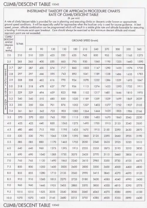
Rate of Climb Table - Obstacle protection for missed approach is predicated on the missed approach being initiated at the decision altitude/height (DA/DH) or at the missed approach point and not lower than minimum descent altitude (MDA)
- If the aircraft initiates a missed approach at a point other than the missed approach point (see paragraph 5-4-5b), from below MDA or DA (H), or while conducting a circling maneuver, obstacle clearance is not necessarily provided by following the published missed approach procedure, nor is separation assured from other air traffic in the vicinity
- A climb gradient of at least 200'/Nautical Mile (NM) is required, except for Copter approaches, where a climb of at least 400'/NM is required, unless a higher climb gradient is published in the Pilot Briefing and Procedure Notes section of the approach procedure chart
- Pilots must pre-plan to ensure that the aircraft can meet the climb gradient (expressed in feet per nautical mile) required by the procedure in the event of a missed approach, and be aware that flying at a higher than anticipated ground speed increases the climb rate requirement (feet per minute)
- Instructions on calculating the climb rate required (feet per minute) against the climb gradient (feet per nautical mile) can be found on the performance calculations page
- Tables for the conversion of climb gradients (feet per nautical mile) to climb rate (feet per minute), based on ground speed, are included on page D1 of the U.S. Terminal Procedures booklets
- Reasonable buffers against obstacles are provided for normal maneuvers however, no consideration is given to an abnormally early turn
- Therefore, when an early missed approach is executed, pilots should, unless otherwise cleared by ATC, fly the IAP as specified on the approach plate to the missed approach point at or above the MDA or DH before executing a turning maneuver
- When higher than standard climb gradients are specified, the end point of the non-standard climb will be specified at either an altitude or a fix
- A climb gradient of at least 200'/Nautical Mile (NM) is required, except for Copter approaches, where a climb of at least 400'/NM is required, unless a higher climb gradient is published in the Pilot Briefing and Procedure Notes section of the approach procedure chart
- Pilots must ensure that they have climbed to a safe altitude prior to proceeding off the published missed approach, especially in non-radar environments, as abandoning the missed approach prior to reaching the published altitude may not provide adequate terrain clearance
- This may be accomplished by referencing the Minimum Safe Altitude depiction which displays minimum safe altitudes within 25 NM of the point it is referenced off of (usually the local NAVAID) []
-
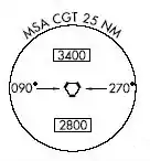
Minimum Safe Altitude
-
-
Alternate Procedures
- Some locations may have a pre-planned alternate missed approach procedure for use in the event the primary NAVAID used for the missed approach procedure is unavailable
- To avoid confusion, the alternate missed approach instructions are not published on the chart
- However, the alternate missed approach holding pattern will be depicted on the instrument approach chart for pilot situational awareness and to assist ATC by not having to issue detailed holding instructions
- When the alternate missed approach procedure is implemented by a Notice to Airmen (NOTAM), it becomes a mandatory part of the procedure
- The NOTAM will specify both the textual instructions and any additional equipment requirements necessary to complete the procedure
- Pilots may reject an ATC clearance for an alternate missed approach that requires equipment not necessary for the published approach procedure when the alternate missed approach is issued after beginning the approach
- However, when the alternate missed approach is issued prior to beginning the approach the pilot must either:
- Accept the entire procedure (including the alternate missed approach);
- Request a different approach procedure, or;
- Coordinate with ATC for alternative action to be taken, i.e., proceed to an alternate airport, etc.
- However, when the alternate missed approach is issued prior to beginning the approach the pilot must either:
- If executing a missed approach prior to reaching the MAP, fly the lateral navigation path of the IAP to the MAP and climb to missed approach altitude, unless the IAP establishes a maximum altitude
- A missed approach assumes you were at the MAP at MDA/DH to guarantee obstacle clearance
- If you have to go missed for any reason not at the missed approach point, then turn toward the missed approach point and execute the missed approach
- You should always be thinking about how to execute the missed approach while circling so it is not a surprise if you enter IMC
- The missed approach is executed for the runway the approach started on, not the runway you were circling to
- The initial turn on a missed approach will always be toward the landing runway until established on a segment of the missed approach
-
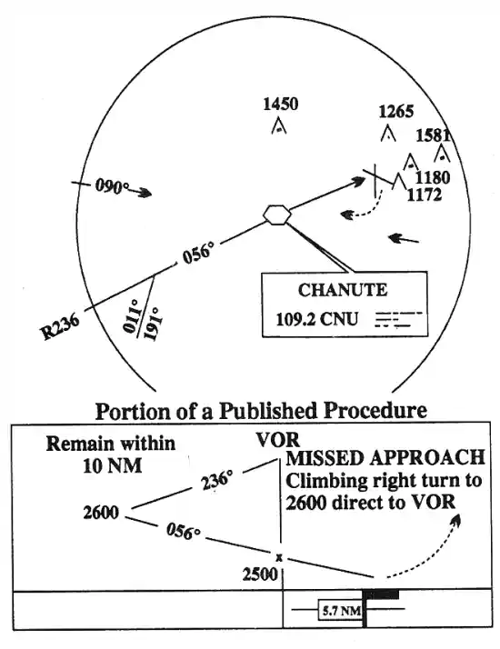
Circling and Missed Approach
Obstruction Clearance Areas - Always request a follow on action after going missed
- Communicate why you are going missed
- A controller may issue modified instructions, which supersede the published instructions
- Stick to the published approach until ATC tells you otherwise
- If executing instructions different from those on the procedure as dictated by approach, call on the go" or "executing climb out" to reduce confusion
- Remember an MDA is a MINIMUM, you are not allowed to sink below it, period, not even by a foot
- Decision altitude, on the other hand, has a built in buffer to allow for missed at that altitude, to sink down as power is brought in, and climb out begins
- If you think your approach may result in a missed, put a "DRAFT" on request:
- Destination
- Route
- Altitude
- Fuel State
- Time En-route
-
Communicate
If Tower: "[Place] tower, [Callsign], missed approach [Reason]" If Departure: "[Place] departure, [Callsign] missed approach off of [Location] climbing through [Altitude] for [Altitude] with request" "DRAFT:" "[Callsign] would like to put a clearance on request to [Destination] via [Route], [Altitude], fuel [Fuel State in Time], Time [Time En-route]" -
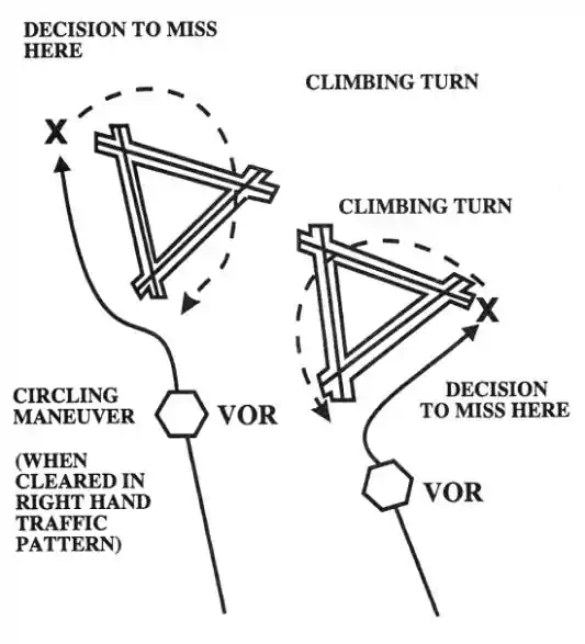
AIM, Figure 5-4-29. Missed Approach
-
-
Circle-to-Land (Circling Maneuver)
- A circle-to-land is a maneuver performed at the end of an instrument approach to land on a runway different from the runway which you flew the instrument approach to
- If visual reference is lost while circling-to-land from an instrument approach, the missed approach specified for that particular procedure must be followed (unless an alternate missed approach procedure is specified by ATC)
- To become established on the prescribed missed approach course, the pilot should make an initial climbing turn toward the landing runway and continue the turn until established on the missed approach course
- Inasmuch as the circling maneuver may be accomplished in more than one direction, different patterns will be required to become established on the prescribed missed approach course, depending on the aircraft position at the time visual reference is lost
- Adherence to the procedure will help assure that an aircraft will remain laterally within the circling and missed approach obstruction clearance areas
- Refer to paragraph h concerning vertical obstruction clearance when starting a missed approach at other than the MAP []
-
Lost Communications Missed Approach
- If marginal weather conditions exist at destination (and possibly low on fuel after a long flight) file a flight plan or DRAFT with the controller in case of missed approach prior to commencing the approach
- In case of lost communication during the approach and subsequently you take a missed approach due to weather considerations:
- Squawk 7600
- Follow the published missed approach instructions to ensure adequate obstruction clearance
Route:
- Proceed to the alternate IAF as filed and commence an approach
Altitude:
- The EXPECTED altitude, if given one, after filing a DRAFT or;
- Your option of the highest of the two emergency safe altitudes depicted on the destination and alternate approach procedure charts if fields are within 200 NM or each other or
- At flight level 18,000'
- If destination altimeter is 29.92 inches or higher, fly FL180
- If destination altimeter is less than 29.92, fly FL190
-
Missed Approach Responsibilities
-
Pilot Responsibilities:
- Executes a missed approach when one of the following conditions exist:
- Arrival at the Missed Approach Point (MAP) or the Decision Height (DH) and visual reference to the runway environment is insufficient to complete the landing
- Determines that a safe approach or landing is not possible (see subparagraph 5-4-21h)
- Instructed to do so by ATC
- Advises ATC that a missed approach will be made. Include the reason for the missed approach unless the missed approach is initiated by ATC
- Complies with the missed approach instructions for the IAP being executed from the MAP, unless other missed approach instructions are specified by ATC
- If executing a missed approach prior to reaching the MAP, fly the lateral navigation path of the instrument procedure to the MAP. Climb to the altitude specified in the missed approach procedure, except when a maximum altitude is specified between the final approach fix (FAF) and the MAP. In that case, comply with the maximum altitude restriction. Note, this may require a continued descent on the final approach
- Cold Temperature Airports (CTA) are designated by a snowflake ICON and temperature in Celsius (C) that are published in the notes box of the middle briefing strip on an instrument approach procedure (IAP). Pilots should apply a cold temperature correction to the missed approach final holding altitude when the reported temperature is at or below the CTA temperature limitation. Pilots must inform ATC of the correction
- AIM, Chapter 7, Section 3, Cold Temperature Barometric Altimeter Errors, Setting Procedures, and Cold Temperature Airports (CTA)
- Following a missed approach, requests clearance for specific action; i.e., another approach, hold for improved conditions, proceed to an alternate airport, etc.
- Executes a missed approach when one of the following conditions exist:
-
Air Traffic Controller Responsibilities:
- Issues an approved alternate missed approach procedure if it is desired that the pilot execute a procedure other than as depicted on the instrument approach chart
- May vector a radar identified aircraft executing a missed approach when operationally advantageous to the pilot or the controller
- In response to the pilot's stated intentions, issues a clearance to an alternate airport, to a holding fix, or for reentry into the approach sequence, as traffic conditions permit
-
-
Missed Approach Procedure
WARNING:
All procedures are GENERALIZED.
Use the Pilot Operating Handbook (POH) procedures for specific aircraft performance and limitations.
and/or current Standard Operating Procedures (SOPs).- At the missed approach point without the approach lights/runway/airport and/or not in a position to make a normal approach and landing, call out, missed approach.
- While the pilot is likely to be flying level at MDA at this point, pilots are descending into DAs, and therefore a descent below DA is expected and not a problem, so long as the pilot initiated the missed approach at the DA.
- Simultaneously establish an appropriate climb attitude (based on airspeed/pitch attitude at the MAP) and apply full power.
- Verify that the mixture control is in the full forward (full rich) position.
- Often times the addition of power and subsequent airspeed increase is necessary before pulling the nose up as the aircraft may be on the backside of the power curve and performance therefore slower to respond.
- Set the pitch to establish and maintain Vx or Vy, as appropriate.
- If applicable, retract the flaps one increment.
- With a positive rate of climb established, callout (over the ICS), "Positive Climb."
- As the aircraft accelerates, if applicable, retract the flaps one increment
- As the aircraft accelerates, if applicable, retract the flaps to up
- Report the missed approach to ATC and, if applicable, advise intention
- At 500' AGL, lower the pitch to establish and maintain a cruise climb
- Complete the Climb Flow/Checklist
- Comply with the published missed approach procedure, or as directed
-
Missed Approach Common Errors
- Failure to have essential knowledge of the information on the instrument approach chart
- Incorrect communication procedures or noncompliance with ATC clearances or instruction
- Failure to accomplish checklist items
- Faulty basic instrument flying techniques
-
Missed Approach Best Practices
- When executing a missed approach, advise ATC and, comply with the missed approach instructions for the procedure being used, or with an alternate missed approach procedure specified by ATC
- When approach has been missed, request clearance for specific action; i.e., to alternative airport, another approach, etc.
- Add power, and rotate gradually, accelerating to climbout speed, and check for two positive rates of climb (Altimeter & VSI)
- Clean up the aircraft as appropriate for aircraft flown (refer to your Pilot Information Manual for appropriate configurations)
- Climb out at appropriate speed
- For MAP procedures that have a speed restriction below 200 KCAS, while turning to the MAP heading to keep a small radius, leave the gear and flaps down and fly on-speed AOA at 5° nose-up until established on the radial, OR fly HALF flaps until on the radial
- If executing the missed due to an inability to break out and land:
- Consider immediately diverting to the planned alternate unless you have reason to believe weather is improving sufficiently to break out
- If the approach was poorly flown, reflying it with emphasize on hitting the numbers
- If there is an emergency, weigh the impacts of flying again, trying another approach with lower minimums, or diverting
-
Missed Approach Case Studies
- National Transportation Safety Board (NTSB) Identification: CEN22FA069:
- The NTSB determines the probable cause(s) of this accident to be: The pilot's failure to adhere to the published instrument approach procedure, which resulted in controlled flight into terrain
- National Transportation Safety Board (NTSB) Identification: ERA21LA101:
- The NTSB determines the probable cause(s) of this accident to be: The pilot's in-flight loss of airplane control due to spatial disorientation during a missed approach in instrument meteorological conditions
- National Transportation Safety Board (NTSB) Identification: CEN22FA069:
-
Missed Approaches Conclusion
- Instrument approaches should be flown with the intention of executing a missed and the possibility of a landing
- If a missed approach is required, advise ATC and include the reason (unless initiated by ATC). Comply with the missed approach instructions for the instrument approach procedure being executed, unless otherwise directed by ATC
- It is legal to request another attempt, but doing so should be based on a reasonable expectation that the result will be different, and not to delay the decision to an alternate
- If compliance with published or alternate missed approach instructions is concerning (for example, it will place you into dangerous weather), then request instructions that mitigate the hazard
- To learn more about instrument procedures, be sure to check out the Instrument Procedures Handbook online or in paperback
- In the case of an ILS where circling is permitted, circling minimums are published, but the missed approach point is at the published missed approach point, not where the glide slope intercepts the circling minimums.
- Note that in the case of an approach continuing visually (breaking out) but a missed is subsequently required, executing the missed approach, even if outside of the protected airspace standards, is all you have
- As part of preflight or approach brief, any published ODPs should be reviewed to get a better idea of hazards on the missed
- Instrument flying is fatiguing meaning a missed approach may be required when most exhausted
- For this reason, don't hesitate to fly to an alternate if required
- Pilots can visit the FAA's Instrument Flight Procedures Information Gateway to review and submit questions related to the how and why certain procedures are as they are
- Still looking for something? Continue searching:
Direction Finding Instrument Approaches
- Direction Finder (DF) equipment has long been used to locate lost aircraft and to guide aircraft to areas of good weather or to airports
- One of the most common systems that helps pilots, without being aware of its operation
- Now at most DF equipped airports, DF instrument approaches may be given to aircraft in a distress or urgency condition
- It is a ground-based radio receiver used by the operator of the ground station
- FAA facilities that provide VHF/DF services are identified in the Chart Supplement U.S..
- The equipment consists of a directional antenna system and a VHF radio receiver
- The VHF/DF receiver display indicates the magnetic direction of the aircraft from the ground station each time the aircraft transmits
- DF equipment is of particular value in locating lost aircraft and in helping to identify aircraft on radar
- DF IAPs are for emergency use only and will not be used in IFR weather conditions, unless the pilot has declared a distress or urgency condition
- Experience has shown that most emergencies requiring DF assistance involve pilots with little flight experience. With this in mind, DF approach procedures provide maximum flight stability in the approach by using small turns, and wings-level descents. The DF specialist will give the pilot headings to fly and tell the pilot when to begin descent
- DF IAPs are for emergency use only and will not be used in IFR weather conditions unless the pilot has declared a distress or urgency condition
- To become familiar with the procedures and other benefits of DF, pilots are urged to request practice DF guidance and approaches in VFR weather conditions
- DF specialists welcome the practice and will honor such requests, workload permitting
-
Direction Finding Instrument Approach Procedure
Contact Approaches
- A contact approach is an approach procedure that may be used by a pilot (with prior authorization from ATC) instead of conducting a standard or special IAP to an airport.
- An example where this becomes necessary is if the ground visibility is reported too low for a visual flight rules (VFR) approach.
- Still, the flight visibility is clearly acceptable, and the field is in sight.
- Pilots operating in accordance with an IFR flight plan, provided they meet the requirements, can reasonably expect to continue to the destination airport in those conditions, and may request ATC authorization for a contact approach.
- The tower is likely either in or receiving reports from sensors that the field is IFR.
- Not intended for use by a pilot on an IFR flight clearance to operate to an airport not having a published and functioning IAP, nor is it intended for an aircraft to conduct an instrument approach to one airport and then, when "in the clear," discontinue that approach and proceed to another airport.
- Nor is it intended for an aircraft to conduct an instrument approach to one airport and then, when "in the clear," discontinue that approach and proceed to another airport.
- Pilot assumes responsibility for obstruction clearance.
- If under radar services, they will terminate when ATC instructs the pilot to change to an advisory frequency/tower.
- Provides approved separation between aircraft cleared for a contact approach and other IFR or special VFR aircraft.
- When using vertical separation, it does not assign a fixed altitude, but clears the aircraft at or below an altitude which is at least 1000' below any IFR traffic, but not below MSA (91.119).
- Begins when the approach is approved and terminates automatically when told to contact the tower.
-
Pilot Requirements:
- The pilot has specifically requested the approach (ATC cannot solicit).
- Pilot: "[Callsign] request contact approach."
- Clear of clouds.
- 1 mile of flight visibility.
- The pilot has reasonable expectations to continue in the above conditions.
- The pilot must advise ATC the moment any of the above are not true.
- The pilot has specifically requested the approach (ATC cannot solicit).
-
Controller Requirements:
- Again, the pilot has specifically requested the approach.
- The reported ground visibility is at least 1 mile.
- The airport has a standard or special IAP.
- Apply approved separation between aircraft so cleared and between these aircraft and other IFR or special VFR aircraft.
- ATC will issue alternative instructions if, in their judgment, weather conditions may make completion of the approach impracticable.
- ATC: "Cleared contact approach at or above [Altitude], [Routing]. If not possible, [Alternative Procedures] and advise."
-
Contact Approach Use Cases
- Contact approaches are helpful for a variety of cases, including:
- When on an IFR flight plan, break out with the airport in sight before beginning an instrument approach.
- When an airport experiences a weather phenomenon that would prevent a breakout with limited instrument approach options, but contact approach procedures are available to conduct a VFR approach.
- Contact approaches are helpful for a variety of cases, including:
Simultaneous Approaches
-
ILS Approaches to Parallel Runways:
- ATC procedures permit ILS/RNAV/GLS instrument approach operations to dual or triple parallel runway configurations.
- ILS/RNAV/GLS approaches to parallel runways are grouped into three classes:
- The classification of a parallel runway approach procedure is dependent on adjacent parallel runway centerline separation, ATC procedures, and airport ATC final approach radar monitoring and communications capabilities.
- At some airports, one or more approach courses may be offset up to 3°.
- ILS approaches with offset localizer configurations result in loss of Category II/III capabilities and an increase in decision altitude/height (50')
- RNAV approach procedures that are approved for simultaneous operations require GPS as the sensor for position updating.
- VOR/DME, DME/DME and IRU RNAV updating is not authorized.
- Depending on weather conditions, traffic volume, and the specific combination of runways being utilized for arrival operations, a runway may be used for different types of simultaneous operations, including closely spaced dependent or independent approaches.
- Parallel approach operations demand heightened pilot situational awareness; therefore, pilots should ensure they understand the type of operation and ask ATC for clarification if necessary.
- A thorough Approach Procedure Chart review should be conducted with, as a minimum, emphasis on the following approach chart information:
- Name and number of the approach.
- Localizer frequency.
- Inbound localizer/azimuth course.
- Glideslope/glidepath intercept altitude.
- Glideslope crossing altitude at the final approach fix.
- Decision height.
- Missed approach instructions.
- Special notes/procedures.
- The assigned runway location/proximity to adjacent runways.
- Pilots are informed by ATC or through the ATIS that simultaneous approaches are in use.
- The close proximity of adjacent aircraft conducting simultaneous independent approaches, especially simultaneous close parallel PRM approaches mandates strict pilot compliance with all ATC clearances. ATC assigned airspeeds, altitudes, and headings must be complied with in a timely manner. Autopilot coupled approaches require pilot knowledge of procedures necessary to comply with ATC instructions. Simultaneous independent approaches, particularly simultaneous close parallel PRM approaches necessitate precise approach course tracking to minimize final monitor controller intervention, and unwanted No Transgression Zone (NTZ) penetration. In the unlikely event of a breakout, ATC will not assign altitudes lower than the minimum vectoring altitude. Pilots should notify ATC immediately if there is a degradation of aircraft or navigation systems
- Strict radio discipline is mandatory during simultaneous independent and simultaneous close parallel PRM approach operations. This includes an alert listening watch and the avoidance of lengthy, unnecessary radio transmissions. Attention must be given to proper call sign usage to prevent the inadvertent execution of clearances intended for another aircraft. Use of abbreviated call signs must be avoided to preclude confusion of aircraft with similar sounding call signs. Pilots must be alert to unusually long periods of silence or any unusual background sounds in their radio receiver. A stuck microphone may block the issuance of ATC instructions on the tower frequency by the final monitor controller during simultaneous independent and simultaneous close parallel PRM approaches. In the case of PRM approaches, the use of a second frequency by the monitor controller mitigates the "stuck mike" or other blockage on the tower frequency
- REFERENCE-AIM, Chapter 4, Section 2, Radio Communications Phraseology and Techniques, gives additional communications information
- Use of Traffic Collision Avoidance Systems (TCAS) provides an additional element of safety to parallel approach operations. Pilots should follow recommended TCAS operating procedures presented in approved flight manuals, original equipment manufacturer recommendations, professional newsletters, and FAA publications
-
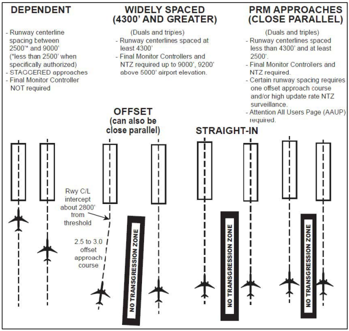
Simultaneous Approaches
(Approach Courses Parallel and Offset between 2.5 and 3.0 degrees)
-
Simultaneous Dependent Approaches
- Permit IAPs to dual or triple parallel runway configurations
- Simultaneous dependent approaches are an ATC procedure permitting approaches to airports having parallel runway centerlines separated by at least 2,500 feet up to 9,000 feet. Integral parts of a total system are ILS or other system providing approach navigation, radar, communications, ATC procedures, and required airborne equipment. RNAV equipment in the aircraft or GLS equipment on the ground and in the aircraft may replace the required airborne and ground based ILS equipment. Although non-precision minimums may be published, pilots must only use those procedures specifically authorized by chart note. For example, the chart note "LNAV NA during simultaneous operations," requires vertical guidance. When given a choice, pilots should always fly a precision approach whenever possible
- A simultaneous dependent approach differs from a simultaneous independent approach in that, the minimum distance between parallel runway centerlines may be reduced; there is no requirement for radar monitoring or advisories; and a staggered separation of aircraft on the adjacent final course is required
- A minimum of 1.0 NM radar separation (diagonal) is required between successive aircraft on the adjacent final approach course when runway centerlines are at least 2,500 feet but no more than 3,600 feet apart. A minimum of 1.5 NM radar separation (diagonal) is required between successive aircraft on the adjacent final approach course when runway centerlines are more than 3,600 feet but no more than 8,300 feet apart. When runway centerlines are more than 8,300 feet but no more than 9,000 feet apart a minimum of 2 NM diagonal radar separation is provided. Aircraft on the same final approach course within 10 NM of the runway end are provided a minimum of 3 NM radar separation, reduced to 2.5 NM in certain circumstances. In addition, a minimum of 1,000 feet vertical or a minimum of three miles radar separation is provided between aircraft during turn on to the parallel final approach course
- Whenever parallel approaches are in use, pilots are informed by ATC or via the ATIS that approaches to both runways are in use. The charted IAP also notes which runways may be used simultaneously. In addition, the radar controller will have the interphone capability of communicating with the tower controller where separation responsibility has not been delegated to the tower
- NOTE: ATC will not specifically identify these operations as being dependent when advertised on the ATIS
- EXAMPLE: Simultaneous ILS Runway 19 right and ILS Runway 19 left in use
- At certain airports, simultaneous dependent approaches are permitted to runways spaced less than 2,500 feet apart. In this case, ATC will provide no less than the minimum authorized diagonal separation with the leader always arriving on the same runway. The trailing aircraft is permitted reduced diagonal separation, instead of the single runway separation normally utilized for runways spaced less than 2,500 feet apart. For wake turbulence mitigation reasons:
- Reduced diagonal spacing is only permitted when certain aircraft wake category pairings exist; typically when the leader is either in the large or small wake turbulence category, and
- All aircraft must descend on the glideslope from the altitude at which they were cleared for the approach during these operations
- When reduced separation is authorized, the IAP briefing strip indicates that simultaneous operations require the use of vertical guidance and that the pilot should maintain last assigned altitude until intercepting the glideslope. No special pilot training is required to participate in these operations
- Either simultaneous dependent approaches with reduced separation or SOIA PRM approaches may be conducted to Runways 28R and 28L at KSFO spaced 750 feet apart, depending on weather conditions and traffic volume. Pilots should use caution so as not to confuse these operations. Plan for SOIA procedures only when ATC assigns a PRM approach or the ATIS advertises PRM approaches are in use. KSFO is the only airport where both procedures are presently conducted
- AIM, Paragraph 5-4-16, Simultaneous Close Parallel PRM Approaches and Simultaneous Offset Instrument Approaches (SOIA)
-

Simultaneous Approaches
(Parallel Runways and Approach Courses)
-
Simultaneous Independent ILS/RNAV/GLS Approaches
System:
- An approach system permitting simultaneous approaches to parallel runways with centerlines separated by at least 4,300 feet. Separation between 4,300 and 9,000 feet (9,200' for airports above 5,000') utilizing NTZ final monitor controllers. Simultaneous independent approaches require NTZ radar monitoring to ensure separation between aircraft on the adjacent parallel approach course. Aircraft position is tracked by final monitor controllers who will issue instructions to aircraft observed deviating from the assigned final approach course. Staggered radar separation procedures are not utilized. Integral parts of a total system are radar, communications, ATC procedures, and ILS or other required airborne equipment. A chart note identifies that the approach is authorized for simultaneous use
- When simultaneous operations are in use, it will be advertised on the ATIS. When advised that simultaneous approaches are in use, pilots must advise approach control immediately of malfunctioning or inoperative receivers, or if a simultaneous approach is not desired. Although non-precision minimums may be published, pilots must only use those procedures specifically authorized by chart note. For example, the chart note "LNAV NA during simultaneous operations," requires vertical guidance. When given a choice, pilots should always fly a precision approach whenever possible
- ATC does not use the word independent or parallel when advertising these operations on the ATIS
- Simultaneous ILS Runway 24 left and ILS Runway 24 right approaches in use
Radar Services:
- These services are provided for each simultaneous independent approach
- During turn on to parallel final approach, aircraft are normally provided 3 miles radar separation or a minimum of 1,000 feet vertical separation. The assigned altitude must be maintained until intercepting the glidepath, unless cleared otherwise by ATC. Aircraft will not be vectored to intercept the final approach course at an angle greater than thirty degrees
- Some simultaneous operations permit the aircraft to track an RNAV course beginning on downwind and continuing in a turn to intercept the final approach course. In this case, separation with the aircraft on the adjacent final approach course is provided by the monitor controller with reference to an NTZ
- The final monitor controller will have the capability of overriding the tower controller on the tower frequency
- Pilots will be instructed to contact the tower frequency prior to the point where NTZ monitoring begins
- Aircraft observed to overshoot the turn-on or to continue on a track which will penetrate the NTZ will be instructed to return to the correct final approach course immediately. The final monitor controller may cancel the approach clearance, and issue missed approach or other instructions to the deviating aircraft
- PHRASEOLOGY: "(Aircraft call sign) YOU HAVE CROSSED THE FINAL APPROACH COURSE. TURN (left/right) IMMEDIATELY AND RETURN TO THE FINAL APPROACH COURSE," or "(aircraft call sign) TURN (left/right) AND RETURN TO THE FINAL APPROACH COURSE"
- If a deviating aircraft fails to respond to such instructions or is observed penetrating the NTZ, the aircraft on the adjacent final approach course (if threatened), will be issued a breakout instruction
- PHRASEOLOGY: "TRAFFIC ALERT (aircraft call sign) TURN (left/right) IMMEDIATELY HEADING (degrees), (climb/descend) AND MAINTAIN (altitude)"
- Radar monitoring will automatically be terminated when visual separation is applied, the aircraft reports the approach lights or runway in sight, or the aircraft is 1 NM or less from the runway threshold. Final monitor controllers will not advise pilots when radar monitoring is terminated
- Simultaneous independent approaches conducted to runways spaced greater than 9,000 feet (or 9,200' at airports above 5,000') do not require an NTZ. However, from a pilot's perspective, the same alerts relative to deviating aircraft will be provided by ATC as are provided when an NTZ is being monitored. Pilots may not be aware as to whether or not an NTZ is being monitored
-

Simultaneous Independent ILS/RNAV/GLS Approaches
-
Simultaneous Close Parallel PRM Approaches and Simultaneous Offset Instrument Approaches (SOIA)
System:
-

PRM Approaches: Simultaneous Close Parallel - PRM is an acronym for the high update rate Precision Runway Monitor surveillance system which is required to monitor the No Transgression Zone (NTZ) for specific parallel runway separations used to conduct simultaneous close parallel approaches. PRM is also published in the title as part of the approach name for IAPs used to conduct
- Simultaneous Close Parallel approaches. "PRM" alerts pilots that specific airborne equipment, training, and procedures are applicable. Because Simultaneous Close Parallel PRM approaches are independent, the NTZ and normal operating zone (NOZ) airspace between the final approach courses is monitored by two monitor controllers, one for each approach course. The NTZ monitoring system (final monitor aid) consists of a high resolution ATC radar display with automated tracking software which provides monitor controllers with aircraft identification, position, speed, and a ten-second projected position, as well as visual and aural NTZ penetration alerts. A PRM high update rate surveillance sensor is a component of this system only for specific runway spacing
- Simultaneous Close Parallel PRM approaches, whether conducted utilizing a high update rate PRM surveillance sensor or not, must meet all of the following requirements: pilot training,PRM in the approach title,NTZ monitoring utilizing a final monitor aid, radar display, publication of an AAUP, and use of a secondary PRM communications frequency. PRM approaches are depicted on a separate IAP titled (Procedure type) PRM Rwy XXX (Simultaneous Close Parallel or Close Parallel)
- ATC does not use the word "independent" when advertising these operations on the ATIS
- EXAMPLE: Simultaneous ILS PRM Runway 33 left and ILS PRM Runway 33 right approaches in use
- The pilot may request to conduct a different type of PRM approach to the same runway other than the one that is presently being used; for example, RNAV instead of ILS. However, pilots must always obtain ATC approval to conduct a different type of approach. Also, in the event of the loss of ground-based NAVAIDS, the ATIS may advertise other types of PRM approaches to the affected runway or runways
- The Attention All Users Page (AAUP) will address procedures for conducting PRM approaches
-
Requirements and Procedures
- Besides system requirements and pilot procedures as identified in subparagraph a1 above, all pilots must have completed special training before accepting a clearance to conduct a PRM approach
- Pilot Training Requirement. Pilots must complete special pilot training, as outlined below, before accepting a clearance for a simultaneous close parallel PRM approach
- For operations under 14 CFR Parts 121, 129, and 135, pilots must comply with FAA-approved company training as identified in their Operations Specifications. Training includes the requirement for pilots to view the FAA training slide presentation, "Precision Runway Monitor (PRM) Pilot Procedures." Refer to https://www.faa.gov/training_testing/training/prm/ or search key words "FAA PRM" for additional information and to view or download the slide presentation
- For operations under Part 91:
- Pilots operating transport category aircraft must be familiar with PRM operations as contained in this section of the AIM. In addition, pilots operating transport category aircraft must view the slide presentation, "Precision Runway Monitor (PRM) Pilot Procedures." Refer to https://www.faa.gov/training_testing/training/prm/ or search key words "FAA PRM" for additional information and to view or download the slide presentation
- Pilots not operating transport category aircraft must be familiar with PRM and SOIA operations as contained in this section of the AIM. The FAA strongly recommends that pilots not involved in transport category aircraft operations view the FAA training slide presentation, "Precision Runway Monitor (PRM) Pilot Procedures." Refer to https://www.faa.gov/training_testing/training/prm/ or search key words "FAA PRM" for additional information and to view or download the slide presentation
- Depending on weather conditions, traffic volume, and the specific combination of runways being utilized for arrival operations, a runway may be used for different types of simultaneous operations, including closely spaced dependent or independent approaches. Use PRM procedures only when the ATIS advertises their use. For other types of simultaneous approaches
- Pilot Training Requirement. Pilots must complete special pilot training, as outlined below, before accepting a clearance for a simultaneous close parallel PRM approach
- Besides system requirements and pilot procedures as identified in subparagraph a1 above, all pilots must have completed special training before accepting a clearance to conduct a PRM approach
ATC Directed Breakout:
- An ATC directed "breakout" is defined as a vector off the final approach course of a threatened aircraft in response to another aircraft penetrating the NTZ
Dual Communications:
- The aircraft flying the PRM approach must have the capability of enabling the pilot/s to listen to two communications frequencies simultaneously. To avoid blocked transmissions, each runway will have two frequencies, a primary and a PRM monitor frequency. The tower controller will transmit on both frequencies. The monitor controller's transmissions, if needed, will override both frequencies. Pilots will ONLY transmit on the tower controller's frequency, but will listen to both frequencies. Select the PRM monitor frequency audio only when instructed by ATC to contact the tower. The volume levels should be set about the same on both radios so that the pilots will be able to hear transmissions on the PRM frequency if the tower is blocked. Site-specific procedures take precedence over the general information presented in this paragraph. Refer to the AAUP for applicable procedures at specific airports
Radar Services:
- During turn on to parallel final approach, aircraft will be provided 3 miles radar separation or a minimum of 1,000 feet vertical separation. The assigned altitude must be maintained until intercepting the glideslope/glidepath, unless cleared otherwise by ATC. Aircraft will not be vectored to intercept the final approach course at an angle greater than thirty degrees
- The final monitor controller will have the capability of overriding the tower controller on the tower frequency as well as transmitting on the PRM frequency
- Pilots will be instructed to contact the tower frequency prior to the point where NTZ monitoring begins. Pilots will begin monitoring the secondary PRM frequency at that time (see Dual VHF Communications Required below)
- To ensure separation is maintained, and in order to avoid an imminent situation during PRM approaches, pilots must immediately comply with monitor controller instructions
- Aircraft observed to overshoot the turn or to continue on a track which will penetrate the NTZ will be instructed to return to the correct final approach course immediately. The final monitor controller may cancel the approach clearance, and issue missed approach or other instructions to the deviating aircraft
- PHRASEOLOGY: "(Aircraft call sign) YOU HAVE CROSSED THE FINAL APPROACH COURSE. TURN (left/right) IMMEDIATELY AND RETURN TO THE FINAL APPROACH COURSE," or "(Aircraft call sign) TURN (left/right) AND RETURN TO THE FINAL APPROACH COURSE."
- If a deviating aircraft fails to respond to such instructions or is observed penetrating the NTZ, the aircraft on the adjacent final approach course (if threatened) will be issued a breakout instruction
- PHRASEOLOGY: "TRAFFIC ALERT (aircraft call sign) TURN (left/right) IMMEDIATELY HEADING (degrees), (climb/descend) AND MAINTAIN (altitude)"
- Radar monitoring will automatically be terminated when visual separation is applied, or the aircraft reports the approach lights or runway in sight or within 1 NM of the runway threshold. Final monitor controllers will not advise pilots when radar monitoring is terminated
Attention All Users Page (AAUP):
-

PRM Attention All Users Page (AAUP) - At airports that conduct PRM operations, the AAUP informs pilots under the "General" section of information relative to all the PRM approaches published at a specific airport, and this section must be briefed in its entirety. Under the "Runway Specific" section, only items relative to the runway to be used for landing need be briefed. (See FIG 5-4-24.) A single AAUP is utilized for multiple PRM approach charts at the same airport, which are listed on the AAUP. The requirement for informing ATC if the pilot is unable to accept a PRM clearance is also presented. The "General" section of AAUP addresses the following:
- Review of the procedure for executing a climbing or descending breakout;
- Breakout phraseology beginning with the words, "Traffic Alert;"
- Descending on the glideslope/glidepath meets all crossing restrictions;
- Briefing the PRM approach also satisfies the non-PRM approach briefing of the same type of approach to the same runway; and
- Description of the dual communications procedure
- The "Runway Specific" section of the AAUP addresses those issues which only apply to certain runway ends that utilize PRM approaches. There may be no Runway Specific procedures, a single item applicable to only one runway end, or multiple items for a single or multiple runway end/s []
-
-
Simultaneous Offset Instrument Approach (SOIA)
-

SOIA Approach Geometry - SOIA is a procedure used to conduct simultaneous approaches to runways spaced less than 3,000 feet, but at least 750 feet apart. The SOIA procedure utilizes a straight-in PRM approach to one runway, and a PRM offset approach with glideslope/glidepath to the adjacent runway. In SOIA operations, aircraft are paired, with the aircraft conducting the straight-in PRM approach always positioned slightly ahead of the aircraft conducting the offset PRM approach
- The straight-in PRM approach plates used in SOIA operations are identical to other straight-in PRM approach plates, with an additional note, which provides the separation between the two runways used for simultaneous SOIA approaches. The offset PRM approach plate displays the required notations for closely spaced approaches as well as depicts the visual segment of the approach
- Controllers monitor the SOIA PRM approaches in exactly the same manner as is done for other PRM approaches. The procedures and system requirements for SOIA PRM approaches are identical with those used for simultaneous close parallel PRM approaches until near the offset PRM approach missed approach point (MAP), where visual acquisition of the straight-in aircraft by the aircraft conducting the offset PRM approach occurs. Since SOIA PRM approaches are identical to other PRM approaches (except for the visual segment in the offset approach), an understanding of the procedures for conducting PRM approaches is essential before conducting a SOIA PRM operation
- In SOIA, the approach course separation (instead of the runway separation) meets established close parallel approach criteria. (See FIG 5-4-25 for the generic SOIA approach geometry.) A visual segment of the offset PRM approach is established between the offset MAP and the runway threshold. Aircraft transition in visual conditions from the offset course, beginning at the offset MAP, to align with the runway and can be stabilized by 500 feet above ground level (AGL) on the extended runway centerline. A cloud ceiling for the approach is established so that the aircraft conducting the offset approach has nominally at least 30 seconds or more to acquire the leading straight-in aircraft prior to reaching the offset MAP. If visual acquisition is not accomplished prior to crossing the offset MAP, a missed approach must be executed
- Flight Management System (FMS) coding of the offset RNAV PRM and GLS PRM approaches in a SOIA operation is different than other RNAV and GLS approach coding in that it does not match the initial missed approach procedure published on the charted IAP. In the SOIA design of the offset approach, lateral course guidance terminates at the fictitious threshold point (FTP), which is an extension of the final approach course beyond the offset MAP to a point near the runway threshold. The FTP is designated in the approach coding as the MAP so that vertical guidance is available to the pilot to the runway threshold, just as vertical guidance is provided by the offset LDA glideslope. No matter what type of offset approach is being conducted, reliance on lateral guidance is discontinued at the charted MAP and replaced by visual maneuvering to accomplish runway alignment
- As a result of this approach coding, when executing a missed approach at and after passing the charted offset MAP, a heading must initially be flown (either hand-flown or using autopilot "heading mode") before engaging LNAV. If the pilot engages LNAV immediately, the aircraft may continue to track toward the FTP instead of commencing a turn toward the missed approach holding fix. Notes on the charted IAP and in the AAUP make specific reference to this procedure
- Some FMSs do not code waypoints inside of the FAF as part of the approach. Therefore, the depicted MAP on the charted IAP may not be included in the offset approach coding. Pilots utilizing those FMSs may identify the location of the waypoint by noting its distance from the FTP as published on the charted IAP. In those same FMSs, the straight-in SOIA approach will not display a waypoint inside the PFAF. The same procedures may be utilized to identify an uncoded waypoint. In this case, the location is determined by noting its distance from the runway waypoint or using an authorized distance as published on the charted IAP
- Because the FTP is coded as the MAP, the FMS map display will depict the initial missed approach course as beginning at the FTP. This depiction does not match the charted initial missed approach procedure on the IAP. Pilots are reminded that charted IAP guidance is to be followed, not the map display. Once the aircraft completes the initial turn when commencing a missed approach, the remainder of the procedure coding is standard and can be utilized as with any other IAP
-
SOIA Definitions:
SAP:
- The stabilized approach point is a design point along the extended centerline of the intended landing runway on the glide slope/glide path at 500 feet above the runway threshold elevation. It is used to verify a sufficient distance is provided for the visual maneuver after the offset course approach DA to permit the pilots to conform to approved, stabilized approach criteria. The SAP is not published on the IAP
Offset Course DA:
- The point along the LDA, or other offset course, where the course separation with the adjacent ILS, or other straight-in course, reaches the minimum distance permitted to conduct closely spaced approaches. Typically that minimum distance will be 3,000 feet without the use of high update radar; with high update radar, course separation of less than 3,000 ft may be used when validated by a safety study. The altitude of the glide slope/glide path at that point determines the offset course approach decision altitude and is where the NTZ terminates. Maneuvering inside the DA is done in visual conditions
Visual Segment Angle:
- Angle, as determined by the SOIA design tool, formed by the extension of the straight segment of the calculated flight track (between the offset course MAP/DA and the SAP) and the extended runway centerline. The size of the angle is dependent on the aircraft approach categories (Category D or only selected categories/speeds) that are authorized to use the offset course approach and the spacing between the runways
Visibility:
- Distance from the offset course approach DA to runway threshold in statute mile
Procedure:
- The aircraft on the offset course approach must see the runway-landing environment and, if ATC has advised that traffic on the straight-in approach is a factor, the offset course approach aircraft must visually acquire the straight-in approach aircraft and report it in sight to ATC prior to reaching the DA for the offset course approach
CC:
- The Clear of Clouds point is the position on the offset final approach course where aircraft first operate in visual meteorological conditions below the ceiling, when the actual weather conditions are at, or near, the minimum ceiling for SOIA operations. Ceiling is defined by the Aeronautical Information Manual
- SOIA PRM approaches utilize the same dual communications procedures as do other PRM approaches
- At KSFO, pilots conducting SOIA operations select the monitor frequency audio when communicating with the final radar controller, not the tower controller as is customary. In this special case, the monitor controller's transmissions, if required, override the final controller's frequency. This procedure is addressed on the AAUP
- SOIA utilizes the same AAUP format as do other PRM approaches. The minimum weather conditions that are required are listed. Because of the more complex nature of instructions for conducting SOIA approaches, the "Runway Specific" items are more numerous and lengthy
- Examples of SOIA offset runway specific notes:
- Aircraft must remain on the offset course until passing the offset MAP prior to maneuvering to align with the centerline of the offset approach runway
- Pilots are authorized to continue past the offset MAP to align with runway centerline when:
- The straight-in approach traffic is in sight and is expected to remain in sight,
- ATC has been advised that "traffic is in sight." (ATC is not required to acknowledge this transmission),
- The runway environment is in sight. Otherwise, a missed approach must be executed. Between the offset MAP and the runway threshold, pilots conducting the offset PRM approach must not pass the straight-in aircraft and are responsible for separating themselves visually from traffic conducting the straight-in PRM approach to the adjacent runway, which means maneuvering the aircraft as necessary to avoid that traffic until landing, and providing wake turbulence avoidance, if applicable. Pilots maintaining visual separation should advise ATC, as soon as practical, if visual contact with the aircraft conducting the straight-in PRM approach is lost and execute a missed approach unless otherwise instructed by ATC
- Examples of SOIA straight-in runway specific notes:
- To facilitate the offset aircraft in providing wake mitigation, pilots should descend on, not above, the glideslope/glidepath
- Conducting the straight-in approach, pilots should be aware that the aircraft conducting the offset approach will be approaching from the right/left rear and will be operating in close proximity to the straight-in aircraft
- Recap:
- The following are differences between widely spaced simultaneous approaches (at least 4,300 feet between the runway centerlines) and Simultaneous PRM close parallel approaches which are of importance to the pilot:
- Runway Spacing. Prior to PRM simultaneous close parallel approaches, most ATC-directed breakouts were the result of two aircraft in-trail on the same final approach course getting too close together. Two aircraft going in the same direction did not mandate quick reaction times. With PRM closely spaced approaches, two aircraft could be alongside each other, navigating on courses that are separated by less than 4,300 feet and as close as 3,000 feet. In the unlikely event that an aircraft "blunders" off its course and makes a worst case turn of 30 degrees toward the adjacent final approach course, closing speeds of 135 feet per second could occur that constitute the need for quick reaction. A blunder has to be recognized by the monitor controller, and breakout instructions issued to the endangered aircraft. The pilot will not have any warning that a breakout is imminent because the blundering aircraft will be on another frequency. It is important that, when a pilot receives breakout instructions, the assumption is made that a blundering aircraft is about to (or has penetrated the NTZ) and is heading toward his/her approach course. The pilot must initiate a breakout as soon as safety allows. While conducting PRM approaches, pilots must maintain an increased sense of awareness in order to immediately react to an ATC (breakout) instruction and maneuver (as instructed by ATC) away from a blundering aircraft
- Communications. Dual VHF communications procedures should be carefully followed. One of the assumptions made that permits the safe conduct of PRM approaches is that there will be no blocked communications
- Hand-flown Breakouts. The use of the autopilot is encouraged while flying a PRM approach, but the autopilot must be disengaged in the rare event that a breakout is issued. Simulation studies of breakouts have shown that a hand-flown breakout can be initiated consistently faster than a breakout performed using the autopilot
- TCAS. The ATC breakout instruction is the primary means of conflict resolution. TCAS, if installed, provides another form of conflict resolution in the unlikely event other separation standards would fail. TCAS is not required to conduct a closely spaced approach
- The TCAS provides only vertical resolution of aircraft conflicts, while the ATC breakout instruction provides both vertical and horizontal guidance for conflict resolutions. Pilots should always immediately follow the TCAS Resolution Advisory (RA),whenever it is received. Should a TCAS RA be received before, during, or after an ATC breakout instruction is issued, the pilot should follow the RA,even if it conflicts with the climb/descent portion of the breakout maneuver. If following an RA requires deviating from an ATC clearance, the pilot must advise ATC as soon as practical. While following an RA, it is extremely important that the pilot also comply with the turn portion of the ATC breakout instruction unless the pilot determines safety to be factor. Adhering to these procedures assures the pilot that acceptable "breakout" separation margins will always be provided, even in the face of a normal procedural or system failure
- The following are differences between widely spaced simultaneous approaches (at least 4,300 feet between the runway centerlines) and Simultaneous PRM close parallel approaches which are of importance to the pilot:
Simultaneous Converging Instrument Approaches
- Where approved, ATC may conduct instrument approaches simultaneously to converging runways; i.e., runways having an included angle from 15 to 100 degrees
- The basic concept requires that dedicated, separate standard instrument approach procedures be developed for each converging runway included. These approaches can be identified by the letter "V" in the title; for example, "ILS V Rwy 17 (CONVERGING)". Missed Approach Points must be at least 3 miles apart and missed approach procedures ensure that missed approach protected airspace does not overlap
- Other requirements are: radar availability, non-intersecting final approach courses, precision approach capability for each runway and, if runways intersect, controllers must be able to apply visual separation as well as intersecting runway separation criteria. Intersecting runways also require minimums of at least 700 foot ceilings and 2 miles visibility. Straight in approaches and landings must be made
- Whenever simultaneous converging approaches are in use, aircraft will be informed by the controller as soon as feasible after initial contact or via ATIS. Additionally, the radar controller will have direct communications capability with the tower controller where separation responsibility has not been delegated to the tower
Practice Instrument Approaches
- A practice approach is an instrument approach where there is no landing intended.
- Upon request, pilots and controllers will establish a criteria under which the practice approches will be conducted
- Various air traffic incidents have indicated the necessity for the adoption of measures to achieve more organized and controlled operations where practice instrument approaches are conducted
- Performed for instruction or proficiency, keeping in mind the requirements of FAR 61.57.
-
Practice Approach Purpose
- Practice approaches serve practical and regulatory needs
- Practically, they give pilots confidence to fly different approaches into different airfields and in the case of regular routes, allow practice under visual conditions for when they may have to fly an approach under instrument conditions
- Recency regulations require practice approaches be flown and logged to demonstrate instrument currency compliance
-
Practice Approach Criteria
- Practice instrument approaches may be requested by aircraft flying under both Visual Flight Rules (VFR) or Instrument Flight Rules (IFR)
- The subsequent handling by ATC will then depend upon which flight rules are to be observed
- For example:
- If an aircraft flying under VFR requests practice approaches, ATC will include the requirement for the pilot to maintain VFR
- If an aircraft flying under IFR requests practice approaches, ATC will handle you as if you're in instrument meteorological conditions
- Since practice approaches are additive to a controller's workload, they will only be accepted if the controller can manage their current workload and no safety hazard exists
- Practice instrument approaches may be requested by aircraft flying under both Visual Flight Rules (VFR) or Instrument Flight Rules (IFR)
-
Practice Approach Requests
- Before practicing an instrument approach, pilots should inform the approach control facility or the tower of the type of practice approach they desire to make and how they intend to terminate it
- You may request a full stop landing, low approach, an option or to depart (to a cardinal direction, to another airport, etc.)
- This information may be furnished progressively when conducting a series of approaches, but be prepared for controllers to ask for all approaches requested upon initial call
- Pilots not on IFR flight plans desiring practice instrument approaches should always state "practice" when making requests to ATC
- If pilots wish to proceed in accordance with instrument flight rules, they must specifically request and obtain, an IFR clearance
- You: "[Facility], [Callsign] request"
- ATC: "[Callsign], [Facility] go ahead with your request"
- You: "[Facility], [Callsign] request [Approach] followed by [Approaches], [Intention when Complete]"
- Pilots on an IFR flight plan, who have made a series of instrument approaches to full stop landings should inform ATC when they make their final landing
- The controller will control flights practicing instrument approaches so as to ensure that they do not disrupt the flow of arriving and departing itinerant IFR or VFR aircraft
- The priority afforded itinerant aircraft over practice instrument approaches is not intended to be so rigidly applied that it causes grossly inefficient application of services
- A minimum delay to itinerant traffic may be appropriate to allow an aircraft practicing an approach to complete that approach
- Whenever a full approach cannot be approved, the pilot is expected to execute the final portion of the approach
- If separation cannot be provided, such as by tower, then the pilot will be advised
- The controller will control flights practicing instrument approaches so as to ensure that they do not disrupt the flow of arriving and departing itinerant IFR or VFR aircraft
- Always remain particularly on the alert for other aircraft operating in the local pattern or in proximity to the airport
- You may log an instrument approach as an actual instrument approach any time the weather is below 1,000' and 3 SM (qualifying as IFR conditions)
- At airports without a tower, pilots wishing to make practice instrument approaches should notify the facility having control jurisdiction of the desired approach as indicated on the approach chart
- All approach control facilities and ARTCCs are required to publish a Letter to Airmen depicting those airports where they provide standard separation to both VFR and IFR aircraft conducting practice instrument approaches
- The controller will provide approved separation between both VFR and IFR aircraft when authorization is granted to make practice approaches to airports where an approach control facility is located and to certain other airports served by approach control or an ARTCC
- Controller responsibility for separation of VFR aircraft begins at the point where the approach clearance becomes effective, or when the aircraft enters Class B or Class C airspace, or a TRSA, whichever comes first
- VFR aircraft practicing instrument approaches are not automatically authorized to execute the missed approach procedure
- Authorization must be specifically requested by the pilot and approved by the controller
- Separation will not be provided unless the missed approach has been approved by ATC
- Except in an emergency, aircraft cleared to practice instrument approaches must not deviate from the approved procedure until cleared to do so by the controller
- At radar approach control locations when a full approach procedure (procedure turn, etc.,) cannot be approved, pilots should expect to be vectored to a final approach course for a practice instrument approach which is compatible with the general direction of traffic at that airport
- When granting approval for a practice instrument approach, the controller will usually ask the pilot to report to the tower prior to or over the final approach fix inbound (non-precision approaches) or over the outer marker or fix used in lieu of the outer marker inbound (precision approaches)
- When authorization is granted to conduct practice instrument approaches to an airport with a tower, but where approved standard separation is not provided to aircraft conducting practice instrument approaches, the tower will approve the practice approach, instruct the aircraft to maintain VFR and issue traffic information, as required
- When an aircraft notifies a FSS providing Local Airport Advisory to the airport concerned of the intent to conduct a practice instrument approach and whether or not separation is to be provided, the pilot will be instructed to contact the appropriate facility on a specified frequency prior to initiating the approach
- At airports where separation is not provided, the FSS will acknowledge the message and issue known traffic information but will neither approve or disapprove the approach
- Before practicing an instrument approach, pilots should inform the approach control facility or the tower of the type of practice approach they desire to make and how they intend to terminate it
-
Practice Approach Responsibilities
- It is Air Traffic's policy to provide for separation of such operations at locations where approach control facilities are located and, as resources permit, at certain other locations served by ARTCCs or parent approach control facilities
- Pilot requests are subject to ATC traffic, and workload conditions once requested
- Pilots should anticipate that in some instances the controller may find it necessary to deny approval or withdraw previous approval when traffic conditions warrant
- A minimum delay to itinerant traffic may be appropriate to allow an aircraft practicing an approach to complete that approach
- In addition to the normal IFR separation minimums (which includes visual separation) during VFR conditions, 500 feet vertical separation may be applied between VFR aircraft and between a VFR aircraft and the IFR aircraft. Pilots not on IFR flight plans desiring practice instrument approaches should always state 'practice' when making requests to ATC. Controllers will instruct VFR aircraft requesting an instrument approach to maintain VFR. This is to preclude misunderstandings between the pilot and controller as to the status of the aircraft. If pilots wish to proceed in accordance with instrument flight rules, they must specifically request and obtain, an IFR clearance
- Pilots conducting practice instrument approaches should be particularly alert for other aircraft operating in the local traffic pattern or in proximity to the airport
- Remember, if you are VFR, you must comply with basic weather minimums
- It must be clearly understood, however, that even though the controller may be providing separation, pilots on VFR flight plans are required to comply with basic VFR weather minimums (FAR 91.155)
- Application of ATC procedures or any action taken by the controller to avoid traffic conflictions does not relieve IFR and VFR pilots of their responsibility to see-and-avoid other traffic while operating in VFR conditions (14 CFR Section 91.113) - ATC should require you acknowledge to maintain VFR
- In addition to the normal IFR separation minimums (which includes visual separation) during VFR conditions, 500 feet vertical separation may be applied between VFR aircraft and between a VFR aircraft and the IFR aircraft
- This is to preclude misunderstandings between the pilot and controller as to the status of the aircraft
- It is Air Traffic's policy to provide for separation of such operations at locations where approach control facilities are located and, as resources permit, at certain other locations served by ARTCCs or parent approach control facilities
-
Non-Towered Airport Operations
- Pilots conducting practice instrument approaches should be particularly alert for other aircraft that may be departing in the opposite direction
- When conducting any practice approach, regardless of its direction relative to other airport operations, pilots should make announcements on the CTAF as follows:
- Departing the final approach fix, inbound (nonprecision approach) or departing the outer marker or fix used in lieu of the outer marker, inbound (precision approach);
- Established on the final approach segment or immediately upon being released by ATC;
- Upon completion or termination of the approach; and
- Upon executing the missed approach procedure
-
Practice Instrument Approaches Conclusion
- A clearance to land means that appropriate separation on the landing runway will be ensured
- A landing clearance does not relieve the pilot from compliance with any previously issued restriction
- VFR aircraft practicing instrument approaches are not automatically authorized to execute the missed approach procedure
- The authorization must be specifically requested by the pilot and approved by the controller
- Pilots not on IFR flight plans desiring practice instrument approaches should always state ‘practice' when making requests to ATC
- To learn more about instrument procedures, be sure to check out the Instrument Procedures Handbook online or in paperback.
- Pilots can visit the FAA's Instrument Flight Procedures Information Gateway to review and submit questions related to the how and why certain procedures are as they are
- Still looking for something? Continue searching:
- A clearance to land means that appropriate separation on the landing runway will be ensured
High-Altitude Penetration Approaches
- High-altitude approaches allow for the rapid transition from the high-altitude structure to land.
- Outlined similarly to a low altitude approach plate
- They are particularly useful for the military with high performance aircraft that have high fuel burns, especially at the lower altitudes
-
Minute to Live Rule
- You shall not descend at a rate faster than altitude left to go
- 5000' = 5000 fpm max
- 4000' = 4000 fpm max
- 3000' = 3000 fpm max
- 2000' = 2000 fpm max
- 1000' = 1000 fpm max
- Inside the Final Approach Fix: 1000 fpm max
-
Flying a High Altitude Approach
-
Penetration From Holding:
- Choose the appropriate method to accelerate from holding airspeed to 250 KIAS (TACAN penetration speed)
- For fuel conservation:
- Plan to intercept 250 KIAS as you descend out of altitude
- At the fix, lower the nose and begin descent while accelerating to 250 KIAS
- As airspeed approaches 250 KIAS, reduce power to IDLE and extend the speed brakes if necessary
- For timing considerations (CV approaches):
- Accelerate to arrive at the IAF at 250 KIAS
- Once cleared inbound and on course, perform a level speed change from 200 KIAS to 250 KIAS
- At the IAF, simultaneously lower the nose and accelerate to 250 KIAS. At 250 KIAS, reduce power to IDLE and adjust nose attitude and trim to maintain speed, countering the resulting nose pitch-up with forward stick. Re-trim for 250 KIAS
- To begin penetration, the aircraft must be established on the initial approach course
- May be done with or without speed brakes as required for the descent
- During approaches to airfields, retract boards when the profile allows and maintain 250 KIAS
- Unlike airfield approaches, CV penetrations are closely sequenced and require all aircraft to maintain 250 KIAS and 4,000 FPM until 5000' AGL (platform)
- At platform, CV aircraft reduce rate of descent from 4,000 to 2,000 FPM by retracting speed brakes and maintaining 250 KIAS
- REMEMBER TO CALL PLATFORM AND OBEY THE MINUTE TO LIVE RULE
-
In Lieu of an En-Route Descent:
- Pilot is expected to execute the entire IAP unless visual contact is made and a visual or contract approach is request and approved, or if the pilot cancels his IFR flight plan
- It is solely the pilots prerogative to cancel his IFR clearance
- Retention of the IFR clearance does not afford priority over VFR traffic and may have to adjust his flight path as necessary to enter traffic pattern in sequence
- After receiving a revised clearance, or any approach clearance, prior to the final approach descent
- All military pilots will report the newly assigned/designated altitude when they report vacating the previously assigned altitude/flight level
-
En-Route Descent:
- Used to transition from an en-route altitude to the final portion of an instrument or visual approach in lieu of published penetrations
- Type of final approach to be flown (GCA, ILS, etc.) should be understood by both the pilot and the controller prior to commencing the descent
- Routing may be via radar vectors or the NAVAIDs depicted on the high altitude charts
- You may request, or a controller may initiate an en route descent; however, the controller must advise you of intention to provide this service and you may refuse it in favor of a published IAP
Pilot Request: "Request en-route descent to [Airport]" - Prior to issuance of a descent clearance below the highest initial approach fix altitude established for ANY high altitude instrument procedure for the destination airport, the controller will inform the pilot of:
- Type of final approach to expect
- RADAR vectors will be provided to the final course
- Current weather, whenever the ceiling is below either 1,000' or the highest circling minimum, or when visibility is less than 3 miles
- Pilots may request a High Altitude Instrument Approach in lieu of an en-route descent
-
Inside the Final Approach Fix (FAF):
- 1500 PPH should set up a good start descent
- Every 100 PPH = 300 fpm in the landing configuration
- 2000 PPH should keep the aircraft level, boards out
-
-
Single Frequency Approach (SFA)
- Provided to single piloted jet aircraft on an IFR flight plan during the hours of darkness or when the aircraft is in instrument weather conditions
- The abbreviation "SFA" will be shown after the heading "COMMUNICATIONS" in the FLIP IFR En-route Supplement when procedures have been implemented at that station
- For those military fields that do not indicate "SFA," check the RADAR section of the FLIP (terminal) for that airfield
- If they have numerous UHF frequencies available, you can request SFA in the remarks section of the DD-175
- Pilots receiving this service will not be required to change frequency from beginning of penetration to touchdown, except that pilots conducting an en-route descent are required to change frequency when control is transferred from the ARTCC to the terminal facility
- Controllers may discontinue the service to all pilots who cancel IFR flight plans during daylight hours and to those pilots in level flight who cancel IFR flight plans at night
-
Pilot Briefing and Procedure Notes
-
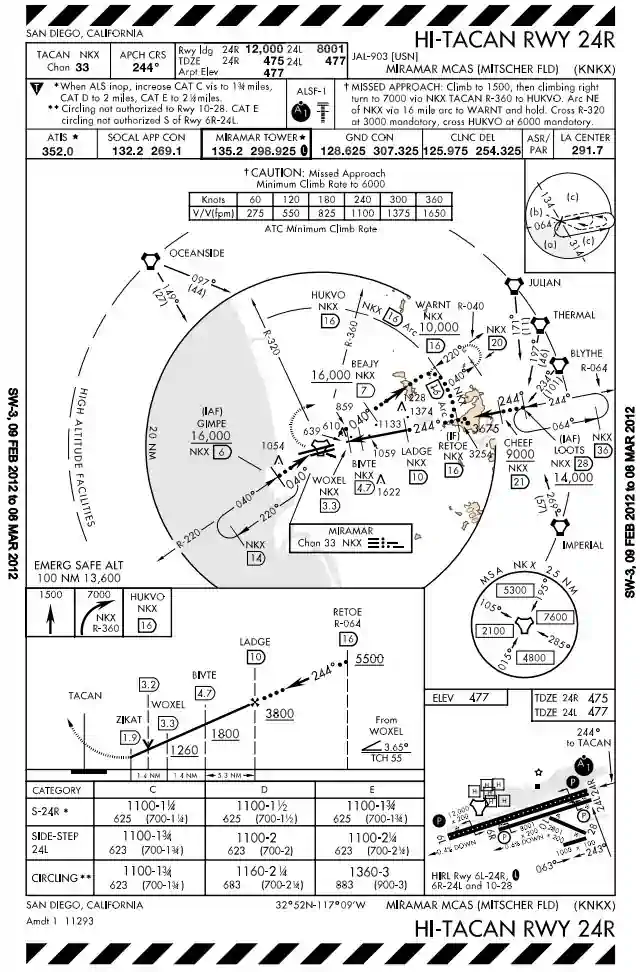
HI-TACAN 24R, Miramar - Includes NAVAIDs required and the final approach course with limited airport information for quick reference
- Notes referencing the approach as a whole will be included
- Approach light systems will be labeled and depicted
- Missed approach instructions are published in text
- Types of radar coverage available (ASR/PAR)
- Frequencies for:
- ATIS
- Approach
- Any headings listed for different frequencies are based on your heading TO the airport
- Example: Heading 270 a note 360-200 would mean you do NOT use that one while a 200-360 would be the correct frequency
-
-
Plan View
- 20-mile radius circle around the navigation facility features encircled by bold print line are to scale
- Feeders will be included when able but normally won't be to scale, expect a radial and DME
- Used mostly to orient one remote NAVAID to another
- The terrain within 6 NM of airfield rises to at least 2,000' above airfield elevation
- The terrain within the plan-view "to scale" area exceeds 4,000' above the airport elevation
- Four basic penetration patterns:
- Straight-in
- Offset
- Arcing
- Teardrop
-
Holding Patterns
- Used until you are cleared to proceed beyond the IAF onto the approach
- Thin solid line with notations indicate arrival holding
- Holding in lieu of a procedure turn is NOT depicted on high altitude approach plates
- Entry diagram found on the upper right corner of plan view to assist with entry
- Missed approach holding patterns are depicted the same as the route
-
Obstacles
- All obstacles are referenced from Mean Sea Level (MSL)
- Single: inverted V with elevation in feet
- Group: two overlapping inverted Vs with elevation in feet
- Highest: large inverted V with elevation in feet
-
Spot Elevation
- All elevations are referenced from Mean Sea Level (MSL)
- Indicated by a dot with elevation in feet
- Highest: bold dot with elevation in feet
- MSA: Minimum safe for a radius of 25 NM from the approach NAVAID (labeled) divided into sectors of at least 90° with different altitudes
- ESA: Emergency safe for a radius of 100 NM from the approach NAVAID (NOT labeled) providing 1,000' / 2,000' clearance in normal and mountainous areas respectively
-
Penetration Track
- Begins at the IAF to the FAF and is depicted by a bold dotted line
- Vertical accent lines depicted altitude restriction DMEs
-
Procedure Track
- Begins at the FAF to the MAP
- Depicted by a thick solid line
-
Missed Approach Route
- Printed instructions in profile view box as with any approach
- Depicted with a dashed line
-
Airport Diagram
- Sketched on approach plate oriented to magnetic north giving basic airport information
- See Airport Diagram.
-

High Altitude Approach Chart Regions
-
FAF to MAP chart
- Used on non-precision approaches when DME unavailable and radio facility not located at field
- Gives the distance from the FAF to MAP in NM
- Gives time to traverse distance at a given ground speed in minutes and seconds
-
Minimums
- Type: straight-in or circling
- Category: B/C/D/E
- Ceiling and visibility required are in parenthesis (RVR next to MDA/DH)
- Minimum Descent Altitude (MDA), Decision Altitude (DA) given in feet MSL
-
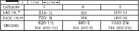
High Altitude Approach Minimums
Instrument Approach and Landing Minimums
- Instrument approaches have specific requirements for flying and landing.
- These approach and landing requirements are established in Federal Aviation Regulation (FAR) 91.175.
-
Approach and Landing Minimums
- If an aircraft that has been cleared to a holding fix and subsequently "cleared...approach" has not received new routing, and even though clearance for the approach may have been issued prior to the aircraft reaching the holding fix, then ATC would expect the pilot to proceed via the holding fix and the feeder route associated with that fix.
- When cleared for the approach, the published off-airway (feeder) routes that lead from the en-route structure to the IAF are part of the approach clearance.
- If a feeder route to an Instrument Approach Fix (IAF) begins at a fix located along the route of flight before reaching the holding fix, and clearance for an approach is issued, a pilot should commence the approach via the published feeder route; i.e., the aircraft would not be expected to overfly the feeder route and return to it.
- If a route of flight directly to the IAF is desired, it should be stated by the controller with phraseology to include the words "direct...," "proceed direct..." or a similar phrase.
- The name of the approach identifies it, even if a component like the glide slope on an ILS is inoperative.
- The controller will use the published name but must advise the aircraft when equipment is inoperative.
- The pilot, not the controller, is responsible for determining your unique requirements/minimums.
- Note that in the absence of a local altimeter setting/ATIS, approach minimums may increase as per the chart or ATC restriction.
- If an aircraft that has been cleared to a holding fix and subsequently "cleared...approach" has not received new routing, and even though clearance for the approach may have been issued prior to the aircraft reaching the holding fix, then ATC would expect the pilot to proceed via the holding fix and the feeder route associated with that fix.
-
Pilot Briefing and Procedure Notes
- Pilot briefing and procedures notes provide additional information that may need to be applied to an approach.
- Examples:
- When a local altimeter has not been received, a correction may need to be added to the published DA or MDA.
-
Definitions
- Holding Fix: a location that is identifiable to a pilot as a reference point in establishing and maintaining the position of an aircraft.
- Feeder Routes: routes that direct pilots toward a location, such as a holding fix for an instrument approach.
-
Approach Clearances
- An aircraft that has been cleared to a holding fix and subsequently "cleared... approach" has not received a new routing. Even though clearance for the approach may have been issued prior to the aircraft reaching the holding fix, ATC would expect the pilot to proceed via the holding fix (his/her last assigned route), and the feeder route associated with that fix (if a feeder route is published on the approach chart) to the initial approach fix (IAF) to commence the approach. WHEN CLEARED FOR THE APPROACH, THE PUBLISHED OFF-AIRWAY (FEEDER) ROUTES THAT LEAD FROM THE EN ROUTE STRUCTURE TO THE IAF ARE PART OF THE APPROACH CLEARANCE.
- If a feeder route to an IAF begins at a fix located along the route of flight prior to reaching the holding fix, and clearance for an approach is issued, a pilot should commence the approach via the published feeder route; i.e., the aircraft would not be expected to overfly the feeder route and return to it. The pilot is expected to commence the approach in a similar manner at the IAF, if the IAF for the procedure is located along the route of flight to the holding fix.
- If a route of flight directly to the initial approach fix is desired, it should be so stated by the controller with phraseology to include the words "direct . . . ," "proceed direct" or a similar phrase which the pilot can interpret without question. When uncertain of the clearance, immediately query ATC as to what route off light is desired.
- The name of an instrument approach, as published, is used to identify the approach, even though a component of the approach aid, such as the glideslope on an Instrument Landing System, is inoperative or unreliable. The controller will use the name of the approach as published, but must advise the aircraft at the time an approach clearance is issued that the inoperative or unreliable approach aid component is unusable, except when the title of the published approach procedures otherwise allows; for example, ILS Rwy 05 or LOC Rwy 05.
- The following applies to aircraft on radar vectors and/or cleared "direct to" in conjunction with an approach clearance:
- Maintain the last altitude assigned by ATC until the aircraft is established on a published segment of a transition route, or approach procedure segment, or other published route, for which a lower altitude is published on the chart. If already on an established route, or approach or arrival segment, you may descend to whatever minimum altitude is listed for that route or segment.
- Continue on the vector heading until intercepting the next published ground track applicable to the approach clearance.
- Once reaching the final approach fix via the published segments, the pilot may continue on approach to a landing.
- If proceeding to an IAF with a published course reversal (procedure turn or hold-in-lieu of PT pattern), except when cleared for a straight-in approach by ATC, the pilot must execute the procedure turn/hold-in-lieu of PT, and complete the approach.
- If cleared to an IAF/IF via a NoPT route, or no procedure turn/hold-in-lieu of PT is published, continue with the published approach.
- In addition to the above, RNAV aircraft may be issued a clearance direct to the IAF/IF at intercept angles not greater than 90 degrees for both conventional and RNAV instrument approaches. Controllers may issue a heading or a course direct to a fix between the IF and FAF at intercept angles not greater than 30 degrees for both conventional and RNAV instrument approaches. In all cases, controllers will assign altitudes that ensure obstacle clearance and will permit a normal descent to the FAF. When clearing aircraft direct to the IF, ATC will radar monitor the aircraft until the IF and will advise the pilot to expect clearance direct to the IF at least 5 miles from the fix. ATC must issue a straight-in approach clearance when clearing an aircraft direct to an IAF/IF with a procedure turn or hold-in-lieu of a procedure turn, and ATC does not want the aircraft to execute the course reversal
- Refer to 14 CFR 91.175 (i).
- RNAV aircraft may be issued a clearance direct to the FAF that is also charted as an IAF, in which case the pilot is expected to execute the depicted procedure turn or hold-in-lieu of procedure turn. ATC will not issue a straight-in approach clearance. If the pilot desires a straight-in approach, they must request vectors to the final approach course outside of the FAF or fly a published "NoPT" route. When visual approaches are in use, ATC may clear an aircraft direct to the FAF.
- In anticipation of a clearance by ATC to any fix published on an instrument approach procedure, pilots of RNAV aircraft are advised to select an appropriate IAF or feeder fix when loading an instrument approach procedure into the RNAV system.
- Selection of "Vectors-to-Final" or "Vectors" option for an instrument approach may prevent approach fixes located outside of the FAF from being loaded into an RNAV system. Therefore, the selection of these options is discouraged due to increased workload for pilots to reprogram the navigation system.
- Arrival Holding.
- Some approach charts have an arrival holding pattern depicted at an IAF or at a feeder fix located along an airway. The arrival hold is depicted using a "thin line" since it is not always a mandatory part of the instrument procedure.
- Arrival holding is charted where holding is frequently required prior to starting the approach procedure so that detailed holding instructions are not required. The arrival holding pattern is not authorized unless assigned by ATC. Holding at the same fix may also be depicted on the en route chart.
- Arrival holding is also charted where it is necessary to use a holding pattern to align the aircraft for procedure entry from an airway due to turn angle limitations imposed by procedure design standards. When the turn angle from an airway into the approach procedure exceeds the permissible limits, an arrival holding pattern may be published along with a note on the procedure specifying the fix, the airway, and arrival direction where use of the arrival hold is required for procedure entry. Unlike a hold-in-lieu of procedure turn, use of the arrival holding pattern is not authorized until assigned by ATC. If ATC does not assign the arrival hold before reaching the holding fix, the pilot should request the hold for procedure entry. Once established on the inbound holding course and an approach clearance has been received, the published procedure can commence. Alternatively, if using the holding pattern for procedure entry is not desired, the pilot may ask ATC for maneuvering airspace to align the aircraft with the feeder course.
- Example: Planview Chart Note: "Proc NA via V343 northeast bound without holding at JOXIT. ATC CLNC REQD."
- Some approach charts have an arrival holding pattern depicted at an IAF or at a feeder fix located along an airway. The arrival hold is depicted using a "thin line" since it is not always a mandatory part of the instrument procedure.
- An RF leg is defined as a constant radius circular path around a defined turn center that starts and terminates at a fix. An RF leg may be published as part of a procedure. Since not all aircraft have the capability to fly these leg types, pilots are responsible for knowing if they can conduct an RNAV approach with an RF leg. Requirements for RF legs will be indicated on the approach chart in the notes section or at the applicable initial approach fix. Controllers will clear RNAV-equipped aircraft for instrument approach procedures containing RF legs:
- Via published transitions, or.
- In accordance with RNAV procedures above.
- ATC will not clear aircraft direct to any waypoint beginning or within an RF leg, and will not assign fix/waypoint crossing speeds in excess of charted speed restrictions.
- EXAMPLE:
- Controllers will not clear aircraft direct to THIRD because that waypoint begins the RF leg, and aircraft cannot be vectored or cleared to TURNN or vectored to intercept the approach segment at any point between THIRD and FORTH because this is the RF leg.
- When necessary to cancel a previously issued approach clearance, the controller will advise the pilot "Cancel Approach Clearance" followed by any additional instructions when applicable.
- You are not cleared to land until tower issues the clearance
- If cleared for the approach by approach control you must wait for tower or query tower to give you a landing clearance.
- Where two or more IAPs are published, pilots will be provided in advance of their arrival with the type of approach to expect or that they may be vectored for a visual approach.
- Broadcast by the controller or ATIS will not be furnished when the visibility is 3 miles or better and the ceiling is at or above the highest initial approach altitude for any low approach established.
- Once cleared for an approach you must report "commencing" or "leaving [Altitude]" as per mandatory calls.
- This is made at the IAF even if you're not changing altitudes so commencing is a better phrase.
- "Cleared for the approach."
- Execute any published approach procedure to the airfield but state your intentions.
- "Cleared for TACAN approach."
- Execute any published TACAN approach procedure to the airfield but state your intention.
- "Cleared for straight-in TACAN approach."
- Execute any published TACAN approach procedure to the active runway which has straight-in minimums authorized, but state your intentions.
- "Cleared for Hi-TACAN runway 24."
- Execute the published TACAN approach procedure for Runway 24 and land straight-in on Runway 24.
- "Cleared for Hi-TACAN runway 24 approach, circle to land runway 6."
- Execute the published TACAN approach procedure for runway 24. Obtain the runway environment and visually circle and land on runway 6 (landing minimums to the adjacent runway will be higher than to the primary runway).
- "Cleared for ILS runway 7 left approach, side-step to runway 7 right."
- Execute the side-step maneuver as soon as possible after the runway or runway environment is in sight (landing minimums to the adjacent runway will be higher than the minimum to the primary runway, but will normally be lower than the published circling minimums).
- When making an IFR approach to an airport not served by a tower or FSS, and after ATC advises "change to advisory frequency approved" you should broadcast your intentions including the type of approach being executed, your position, and when over the final approach fix inbound.
-
Pilot Discretion Means:
- Leave when you want.
- Stop if you want.
- Do it at the rate you want.
-
Runway Environment
- Criteria for the civil pilot continuing an approach is stated in FAR 91.175 as:
- Where a Decision Height (DH)/Decision Altitude (DA) or Minimum Descent Altitude (MDA) is applicable, no pilot may operate an aircraft, except a military of the United States, at any airport below the authorized MDA or continue an approach below the authorized DH unless:
- The aircraft is continuously in a position from which a descent to a landing on the intended runway can be made at a normal rate of descent using normal maneuvers, and for operations conducted under part 121 or part 135 unless that descent rate will allow touchdown to occur within the touchdown zone of the runway of indented landing;
- The flight visibility is not less than the visibility prescribed in the standard instrument approach being used;
- Except for Category II or Category III approach where any necessary visual reference requirements are specified by the Administrator, at least one of the following visual reference for the intended runway is distinctly visible and identifiable to the pilot.
- The approach light system, except that the pilot may not descend below 100' above the touchdown zone elevation using the approach lights as a reference unless the red side row bars are also distinctly visible and identifiable.
- The threshold.
- The threshold markings.
- The threshold lights.
- The runway end identifier lights.
- The visual approach slope indicator.
- The touchdown zone or the touchdown zone markings.
- The touchdown zone lights.
- The runway or runway markings.
- The runway lights.
- No pilot operating an aircraft, except a military aircraft of the United States, may land that aircraft when the flight visibility is less than the visibility prescribed in the standard instrument approach procedure being used.
- Where a Decision Height (DH)/Decision Altitude (DA) or Minimum Descent Altitude (MDA) is applicable, no pilot may operate an aircraft, except a military of the United States, at any airport below the authorized MDA or continue an approach below the authorized DH unless:
- Criteria for the civil pilot continuing an approach is stated in FAR 91.175 as:
-
Obstacle Clearance
- Final approach obstacle clearance is provided from the start of the final segment to the runway or Missed Approach Point (MAP) whichever occurs last.
- If a Sidestep option is incorporated into the approach then obstacle protection is provided by increasing the width of the final approach obstacle clearance area.
- Circling approach: tangential connection of arcs drawn from each runway end, obstacles unable to be cleared will be given rules.
- Example: circling NA E of RWY 17-35, meaning circling not authorized east of runway 17-35.
- Circling approach protected areas are defined by the tangential connection of arcs drawn from each runway end. []
- Circling approach protected areas developed prior to late 2012 used fixed radius distances, dependent on aircraft approach category, as shown in the table on page B2 of the U.S. TPP.
- The approaches using standard circling approach areas can be identified by the absence of the "negative C" symbol on the circling line of minima.
- Circling approach protected areas developed after late 2012 use the radius distance shown in the table on page B2 of the U.S. TPP, dependent on aircraft approach category, and the altitude of the circling MDA, which accounts for true airspeed increase with altitude.
- The approaches using expanded circling approach areas can be identified by the presence of the "negative C" symbol on the circling line of minima. []
- Circling approach protected areas developed prior to late 2012 used fixed radius distances, dependent on aircraft approach category, as shown in the table on page B2 of the U.S. TPP.
- Because of obstacles near the airport, a portion of the circling area may be restricted by a procedural note; for example, "Circling NA E of RWY 17-35." Obstacle clearance is provided at the published minimums (MDA) for the pilot who makes a straight-in approach, side-steps, or circles. Once below the MDA the pilot must see and avoid obstacles. Executing the missed approach after starting to maneuver usually places the aircraft beyond the MAP. The aircraft is clear of obstacles when at or above the MDA while inside the circling area, but simply joining the missed approach ground track from the circling maneuver may not provide vertical obstacle clearance once the aircraft exits the circling area. Additional climb inside the circling area may be required before joining the missed approach track. See Paragraph 5-4-21, Missed Approach, for additional considerations when starting a missed approach at other than the MAP.
-
Precision Obstacle Free Zone (POFZ)
-
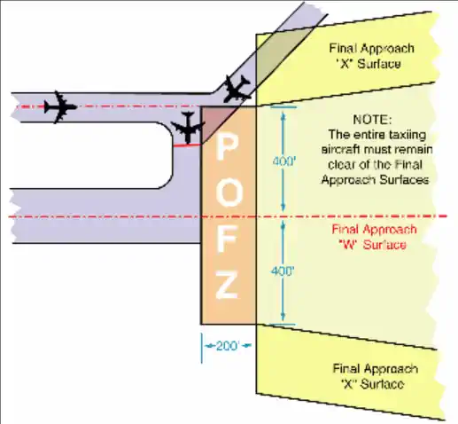
Circling Instructions Example - A volume of airspace above an area beginning at the runway threshold, at threshold elevation, and centered on the extended runway centerline.
- POFZ is 200' (60m) long and 800' (240m) wide.
- The POFZ must be clear when an aircraft on a vertically guided final approach is within 2 Nautical Mile (NM) of the runway threshold and the ceiling is below 250' or visibility is less than 3/4 Statute Miles (SM)(or runway visual range below 4,000 feet).
- If the POFZ is not clear, the MINIMUM authorized height above touchdown (HAT) and visibility is 250' and 3/4 SM.
- The POFZ is considered clear even if the wing of the aircraft holding on a taxiway waiting for runway clearance penetrates the POFZ; however, neither the fuselage nor the tail may infringe on the POFZ.
- The POFZ is applicable at all runway ends including displaced thresholds.
-
Published Approach Minimums:
- Approach minimums are published for different aircraft categories and consist of a minimum altitude (DA, DH, MDA) and required visibility.
- These minimums are determined by applying the appropriate TERPS criteria.
- When a fix is incorporated in a nonprecision final segment, two sets of minimums may be published: one for the pilot that is able to identify the fix, and a second for the pilot that cannot.
- Two sets of minimums may also be published when a second altimeter source is used in the procedure.
- When a nonprecision procedure incorporates both a stepdown fix in the final segment and a second altimeter source, two sets of minimums are published to account for the stepdown fix and a note addresses minimums for the second altimeter source.
-
Straight-in Minimums:
- Obstacle clearance is provided within 30° of the runway alignment and a normal descent can be made from the IFR altitude shown on the IAP to the runway surface
- When either the normal rate of descent or the runway alignment factor of 30 degrees is exceeded, a straight-in minimum is not published and a circling minimum applies.
- The fact that a straight-in minimum is not published does not preclude pilots from landing straight-in if they have the active runway in sight and sufficient time to make a normal approach for landing.
- Under such conditions and when ATC has cleared them for landing on that runway, pilots are not expected to circle even though only circling minimums are published.
- If they desire to circle, they should advise ATC.
- Obstacle clearance is provided within 30° of the runway alignment and a normal descent can be made from the IFR altitude shown on the IAP to the runway surface
-
Side-Step Maneuver Minimums:
- Landing minimums for a side-step maneuver to the adjacent runway will normally be higher than the minimums to the primary runway.
-
Circling Minimums:
- In some busy terminal areas, ATC may not allow circling and circling minimums will not be published. Published circling minimums provide obstacle clearance when pilots remain within the appropriate area of protection. Pilots should remain at or above the circling altitude until the aircraft is continuously in a position from which a descent to a landing on the intended runway can be made at a normal rate of descent using normal maneuvers. Circling may require maneuvers at low altitude, at low airspeed, and in marginal weather conditions. Pilots must use sound judgment, have an in-depth knowledge of their capabilities, and fully understand the aircraft performance to determine the exact circling maneuver since weather, unique airport design, and the aircraft position, altitude, and airspeed must all be considered. The following basic rules apply:
- Maneuver the shortest path to the base or downwind leg, as appropriate, considering existing weather conditions. There is no restriction from passing over the airport or other runways.
- It should be recognized that circling maneuvers may be made while VFR or other flying is in progress at the airport. Standard left turns or specific instruction from the controller for maneuvering must be considered when circling to land.
- At airports without a control tower, it may be desirable to fly over the airport to observe wind and turn indicators and other traffic which may be on the runway or flying in the vicinity of the airport.
- REFERENCE-AC 90-66A, Recommended Standards Traffic patterns for Aeronautical Operations at Airports without Operating Control Towers.
- The missed approach point (MAP) varies depending upon the approach flown. For vertically guided approaches, the MAP is at the decision altitude/decision height. Non-vertically guided and circling procedures share the same MAP and the pilot determines this MAP by timing from the final approach fix, by a fix, a NAVAID, or a waypoint. Circling from a GLS, an ILS without a localizer line of minima or an RNAV (GPS) approach without an LNAV line of minima is prohibited.
- In some busy terminal areas, ATC may not allow circling and circling minimums will not be published. Published circling minimums provide obstacle clearance when pilots remain within the appropriate area of protection. Pilots should remain at or above the circling altitude until the aircraft is continuously in a position from which a descent to a landing on the intended runway can be made at a normal rate of descent using normal maneuvers. Circling may require maneuvers at low altitude, at low airspeed, and in marginal weather conditions. Pilots must use sound judgment, have an in-depth knowledge of their capabilities, and fully understand the aircraft performance to determine the exact circling maneuver since weather, unique airport design, and the aircraft position, altitude, and airspeed must all be considered. The following basic rules apply:
-
Instrument Approach at a Military Field:
- When instrument approaches are conducted by civil aircraft at military airports, they must be conducted in accordance with the procedures and minimums approved by the military agency having jurisdiction over the airport.
- There really is no difference between a military approach plate and a civilian approach plate other than who originated the procedure
- The approach and landing minimums (as well as the rest of the plate) will read the same.
- To determine who originated the procedure you can check the top center of the plate.
- DOD procedures are defined using the abbreviation of the applicable military service in parenthesis; e.g., (USAF), (USN), (USA) while Civil procedures are defined with "FAA" in parenthesis; e.g., (FAA).
- Unless an emergency exists, civil aircraft operating at military airports normally require advance authorization, commonly referred to as "Prior Permission Required" or "PPR."
- Information on obtaining a PPR for a particular military airport can be found in the Chart Supplement U.S.
- There really is no difference between a military approach plate and a civilian approach plate other than who originated the procedure
- When instrument approaches are conducted by civil aircraft at military airports, they must be conducted in accordance with the procedures and minimums approved by the military agency having jurisdiction over the airport.
-
-
Landing Criteria
-
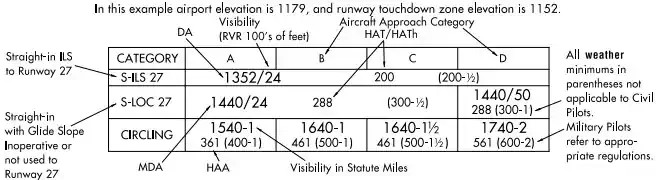
Straight-in Approach Minimum Explanation - Criteria for operating below the DH/DA or MDA for civilian pilots is clearly stated in FAR 91.175(c)(3)
- These requirements call for three criteria:
- In a position to make a safe landing.
- The runway environment is in sight.
- Visibility requirements are met (note no ceiling requirements).
- These requirements call for three criteria:
-
-
Remember
- A clearance for a specific type of approach to an aircraft operating on an IFR flight plan does not mean that landing priority will be given over other traffic.
- Towers handle all aircraft regardless of flight plan on a "first-come, first-serve" basis.
- It may be necessary for the controller to provide a different landing sequence.
- In any case, a landing sequence will be issued to each aircraft as soon as possible.
- When reaching the Final Approach Fix (FAF) you must report it.
- When breaking out, if you have a Heads-Up-Display (HUD) with a "ghost vector," check its location before you make a play for the runway as a crosswind correction put in may already have you set up perfectly for the runway.
- When approach terminates IFR on a visual approach, contact tower, if not told so.
- If you may not break out, tell approach control and put your draft on request as an advisory to ATC.
- Note where you break out, should you have to go back into the weather.
-
Runway Visual Range
- Runway Visual Range (RVR) is a tool used to determine ground or flight visibility in deciding whether or not to shoot an approach.
- For converting RVR values that fall between listed values, use the next higher RVR value; do not interpolate.
- Example: when converting 1800 RVR, use 2400 RVR with the resultant visibility of 1/2 mile.
- There are currently two configurations of RVR in the NAS commonly identified as Taskers and New Generation RVR.
- The Taskers are the existing configuration which uses transmissometer technology.
- The New Generation RVRs were deployed in November 1994 and use forward scatter technology.
- The New Generation RVRs are currently being deployed in the NAS to replace the existing Taskers.
- RVR values are measured by transmissometers mounted on 14-foot towers along the runway which consists of:
- Transmissometer projector and related items.
- Transmissometer receiver (detector) and related items.
- Analog recorder.
- Signal data converter and related items.
- Remote digital or remote display programmer.
- The transmissometer projector and receiver are mounted on towers 250 feet apart. A known intensity of light is emitted from the projector and is measured by the receiver. Any obscuring matter such as rain, snow, dust, fog, haze or smoke reduces the light intensity arriving at the receiver. The resultant intensity measurement is then converted to an RVR value by the signal data converter. These values are displayed by readout equipment in the associated air traffic facility and updated approximately once every minute for controller issuance to pilots.
- The signal data converter receives information on the high intensity runway edge light setting in use (step 3, 4, or 5); transmission values from the transmissometer and the sensing of day or night conditions. From the three data sources, the system will compute appropriate RVR values.
- An RVR transmissometer established on a 250 foot baseline provides digital readouts to a minimum of 600 feet, which are displayed in 200 foot increments to 3,000 feet and in 500 foot increments from 3,000 feet to a maximum value of 6,000 feet.
- RVR values for Category IIIa operations extend down to 700 feet RVR; however, only 600 and 800 feet are reportable RVR increments. The 800 RVR reportable value covers a range of 701 feet to 900 feet and is therefore a valid minimum indication of Category IIIa operations.
- Note that while several approaches will include both RVR and Flight Visibility numbers but that is not always the case - such as on Non-Precision approaches.
- Approach categories with the corresponding minimum RVR values. []
-
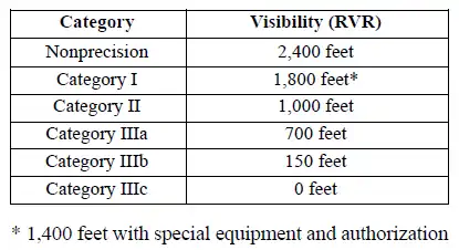
Approach Category/Minimum RVR Table - Ten minute maximum and minimum RVR values for the designated RVR runway are reported in the body of the aviation weather report when the prevailing visibility is less than one mile and/or the RVR is 6,000 feet or less. ATCTs report RVR when the prevailing visibility is 1 mile or less and/or the RVR is 6,000 feet or less.
- Details on the requirements for the operational use of RVR are contained in FAA AC 97-1, "Runway Visual Range (RVR)." Pilots are responsible for compliance with minimums prescribed for their class of operations in the appropriate CFRs and/or operations specifications.
- RVR values are also measured by forward scatter meters mounted on 14-foot frangible fiberglass poles. A full RVR system consists of:
- Forward scatter meter with a transmitter, receiver and associated items.
- A runway light intensity monitor (RLIM).
- An ambient light sensor (ALS).
- A data processor unit (DPU).
- Controller display (CD).
- The forward scatter meter is mounted on a 14-foot frangible pole. Infrared light is emitted from the transmitter and received by the receiver. Any obscuring matter such as rain, snow, dust, fog, haze or smoke increases the amount of scattered light reaching the receiver. The resulting measurement along with inputs from the runway light intensity monitor and the ambient light sensor are forwarded to the DPU which calculates the proper RVR value. The RVR values are displayed locally and remotely on controller displays.
- The runway light intensity monitors both the runway edge and centerline light step settings (steps 1 through 5). Centerline light step settings are used for CAT IIIb operations. Edge Light step settings are used for CAT I, II, and IIIa operations.
- New Generation RVRs can measure and display RVR values down to the lowest limits of Category IIIb operations (150 feet RVR). RVR values are displayed in 100 feet increments and are reported as follows:
- 100-feet increments for products below 800'.
- 200-feet increments for products between 800 feet and 3,000'.
- 500-feet increments for products between 3,000 feet and 6,500'.
- 25-meter increments for products below 150 meters.
- 50-meter increments for products between 150 meters and 800 meters.
- 100-meter increments for products between 800 meters and 1,200 meters.
- 200-meter increments for products between 1,200 meters and 2,000 meters.
-
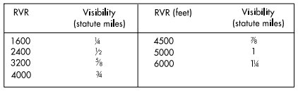
Runway Visual Range (RVR)
- Runway Visual Range (RVR) is a tool used to determine ground or flight visibility in deciding whether or not to shoot an approach.
-
Criteria for Continuing Instrument Approaches to a Landing
- Pilots shall not descend below the prescribed MDA or continue an approach below the decision height (DH) unless they have the runway environment in sight and in their judgment a safe landing can be executed, either straight-in or from a circling approach, whichever is specified in their clearance.
- Precision Approaches: A missed approach shall be executed immediately upon reaching the DH unless the runway environment is in sight and a safe landing can be made. On precision radar approaches, the pilot may expect control instructions until over landing threshold; course and glide path information given after DH shall be considered advisory in nature.
- Non-Precision Approaches: A missed approach shall be executed immediately upon reaching the MAP if visual reference is not established and/or a landing cannot be accomplished. If visual reference is lost while circling to land from a published instrument approach, the missed approach specified for that particular procedure must be followed. To become established on the prescribed missed approach course, the pilot should make an initial climbing turn toward the landing runway then maneuver in the shortest direction to become established on the missed approach course.
-
Landing Priority
- A clearance for a specific type of approach (ILS, RNAV, GLS, ADF, VOR or Visual Approach) to an aircraft operating on an IFR flight plan does not mean that landing priority will be given over other traffic.
- ATCTs handle all aircraft, regardless of the type of flight plan, on a "first-come, first-served" basis.
- Therefore, because of local traffic or runway in use, it may be necessary for the controller in the interest of safety, to provide a different landing sequence.
- In any case, a landing sequence will be issued to each aircraft as soon as possible to enable the pilot to properly adjust the aircraft's flight path.
-
Conclusion
- Occasionally, multiple approaches of the same type may be published to the same runway.
- In these instances, lower minimums may be the reason, but non-standard performance may be required for the lower approach, necessitating standard approach parameters with higher minimums.
- Be sure not to transition from instrument to visual when the runway environment comes into sight, only to lose it again in the weather.
- Breaking out of the weather, especially at night, may be gradual and not support an immediate transition to visual flying.
- Occasionally, multiple approaches of the same type may be published to the same runway.
Instrument Approach Responsibilities
-
Pilot Responsibilities:
- Be aware that the controller issues clearance for approach based only on known traffic
- Follow the procedures as shown on the IAP, including all restrictive notations, such as:
- Procedure not authorized at night;
- Approach not authorized when local area altimeter not available;
- Procedure not authorized when control tower not in operation;
- Procedure not authorized when glide slope not used;
- Straight-in minimums not authorized at night; etc.
- Radar required; or
- The circling minimums published on the instrument approach chart provide adequate obstruction clearance and pilots should not descend below the circling altitude until the aircraft is in a position to make final descent for landing. Sound judgment and knowledge of the pilot's and the aircraft's capabilities are the criteria for determining the exact maneuver in each instance since airport design and the aircraft position, altitude and airspeed must all be considered
- Upon receipt of an approach clearance while on an unpublished route or being radar vectored:
- Complies with the minimum altitude for IFR; and
- Maintains the last assigned altitude until established on a segment of a published route or IAP, at which time published altitudes apply
-
Controller Responsibilities:
- Issues an approach clearance based on known traffic
- Issues an IFR approach clearance only after the aircraft is established on a segment of published route or IAP, or assigns an appropriate altitude for the aircraft to maintain until so established
Communications Release of IFR Aircraft Landing at an Airport Without an Operating Control Tower
- Aircraft operating on an IFR flight plan, landing at an airport without an operating control tower will be advised to change to the airport advisory frequency when direct communications with ATC are no longer required
- Towers and centers do not have nontower airport traffic and runway in use information
- The instrument approach may not be aligned with the runway in use; therefore, if the information has not already been obtained, pilots should make an expeditious change to the airport advisory frequency when authorized
Advance Information on Instrument Approaches
- When landing at airports with approach control services and where two or more IAPs are published, pilots will be provided in advance of their arrival with the type of approach to expect or that they may be vectored for a visual approach
- This information will be broadcast either by a controller or on ATIS
- It will not be furnished when the visibility is three miles or better and the ceiling is at or above the highest initial approach altitude established for any low altitude IAP for the airport
- The purpose of this information is to aid the pilot in planning arrival actions; however, it is not an ATC clearance or commitment and is subject to change
- Pilots should bear in mind that fluctuating weather, shifting winds, blocked runway, etc., are conditions which may result in changes to approach information previously received
- It is important that pilots advise ATC immediately they are unable to execute the approach ATC advised will be used, or if they prefer another type of approach
- Aircraft destined to uncontrolled airports, which have automated weather data with broadcast capability, should monitor the ASOS/AWOS frequency to ascertain the current weather for the airport
- The pilot must advise ATC when he/she has received the broadcast weather and state his/her intentions
- ASOS/AWOS should be set to provide one-minute broadcast weather updates at uncontrolled airports that are without weather broadcast capability by a human observer
- Controllers will consider the long line disseminated weather from an automated weather system at an uncontrolled airport as trend and planning information only and will rely on the pilot for current weather information for the airport. If the pilot is unable to receive the current broadcast weather, the last long line disseminated weather will be issued to the pilot. When receiving IFR services, the pilot/aircraft operator is responsible for determining if weather/visibility is adequate for approach/landing
- When making an IFR approach to an airport not served by a tower or FSS, after ATC advises "CHANGE TO ADVISORY FREQUENCY APPROVED" you should broadcast your intentions, including the type of approach being executed, your position, and when over the final approach fix inbound (nonprecision approach) or when over the outer marker or fix used in lieu of the outer marker inbound (precision approach). Continue to monitor the appropriate frequency (UNICOM, etc.) for reports from other pilots
- Several IAPs, using various navigation and approach aids may be authorized for an airport. ATC may advise that a particular approach procedure is being used, primarily to expedite traffic. If issued a clearance that specifies a particular approach procedure, notify ATC immediately if a different one is desired. In this event it may be necessary for ATC to withhold clearance for the different approach until such time as traffic conditions permit. However, a pilot involved in an emergency situation will be given priority. If the pilot is not familiar with the specific approach procedure, ATC should be advised and they will provide detailed information on the execution of the procedure
IFR Approaches/Ground Vehicle Operations
-
IFR Approaches:
- When operating in accordance with an IFR clearance and ATC approves a change to the advisory frequency, make an expeditious change to the CTAF and employ the recommended traffic advisory procedures
-
Ground Vehicle Operation:
- Airport ground vehicles equipped with radios should monitor the CTAF frequency when operating on the airport movement area and remain clear of runways/taxiways being used by aircraft.
- Radio transmissions from ground vehicles should be confined to safety-related matters.
-
Radio Control of Airport Lighting Systems:
- Whenever possible, the CTAF will be used to control airport lighting systems at airports without operating control towers. This eliminates the need for pilots to change frequencies to turn the lights on and allows a continuous listening watch on a single frequency. The CTAF is published on the instrument approach chart and in other appropriate aeronautical information publications
Instrument Approach Procedures Knowledge Check


Instrument Approach Procedures Conclusion
- While headings and altitudes will change, approaches generally follow the same rules
- IAPs (standard and special, civil and military) are based on joint civil and military criteria contained in the U.S. Standard for TERPS which takes into account the interrelationship between airports, facilities, and the surrounding environment, terrain, obstacles, noise sensitivity, etc.
- It is important that pilots understand these procedures and their use prior to attempting to fly instrument approaches
- Controllers will never solicit the use of a contact approach.
- A pilot adhering to the altitudes, flight paths, and weather minimums depicted on the IAP chart or vectors and altitudes issued by the radar controller, is assured of terrain and obstruction clearance and runway or airport alignment during approach for landing
- The method used to depict prescribed altitudes on instrument approach charts differs according to techniques employed by different chart publishers
- Approach categories maintain safety for aircraft of varying stall speeds, turn performance, etc.
- The faster the airplane, the higher the category.
- The higher the category, the more space is required to safely maneuver on an approach.
- The more space required, generally the higher the minimums.
- 14 CFR Section 91.175(a), Instrument approaches to civil airports, requires the use of SIAPs prescribed for the airport in 14 CFR Part 97 unless otherwise authorized by the Administrator (including ATC)
- Often times you will need to keep many approach charts handy depending on the active runway upon your commencement of an instrument approach
- This can be accomplished by carrying the approach plate book, a chart organizer, or attaching approach chart pockets to a kneeboard.
- To learn more about instrument procedures, be sure to check out the Instrument Procedures Handbook online or in paperback
- Instrument approaches can be complex procedures in the busy terminal environment but don't hesitate to request delayed vectors to set yourself up for success
- A good landing starts with a good approach
- Not all IAPs (radar approaches) are published in chart form
- Check out the FAA's Instrument Flight Procedures (IFP) Inventory Summary.
- To learn more about instrument procedures, be sure to check out the Instrument Procedures Handbook online or in paperback.
- Consider actual versus realized performance when doing any performance calculations
- Consider practicing maneuvers on a flight simulator to introduce yourself to maneuvers or knock off rust
- Review your instrument approach safety knowledge by taking the Air Safety Institute's "Boardwalk Approach", "A Tale of Two ILSs", and "Magic City of the Plains" quiz
- Pilots can visit the FAA's Instrument Flight Procedures Information Gateway to review and submit questions related to the how and why certain procedures are as they are
- Still looking for something? Continue searching:
Instrument Approach Procedures References
- AOPA - Not Authorized At Night.
- Aeronautical Information Manual (1-1-17) Global Positioning System (GPS).
- Aeronautical Information Manual (1-1-20) Precision Approach Systems other than ILS and GLS.
- Aeronautical Information Manual (4-1-5) Communications Release of IFR Aircraft Landing at an Airport Without an Operating Control Tower
- Aeronautical Information Manual (4-1-9) Traffic Advisory Practices at Airports Without Operating Control Towers.
- Aeronautical Information Manual (4-1-10) IFR Approaches/Ground Vehicle Operations.
- Aeronautical Information Manual (4-3-12) Low Approach.
- Aeronautical Information Manual (4-3-21) Practice Instrument Approaches.
- Aeronautical Information Manual (4-3-22) Option Approach.
- Aeronautical Information Manual (4-5-4) Precision Approach Radar (PAR).
- Aeronautical Information Manual (5-4-4) Advance Information on Instrument Approach.
- Aeronautical Information Manual (5-4-5) Instrument Approach Procedure Charts.
- Aeronautical Information Manual (5-4-6) Approach Clearance.
- Aeronautical Information Manual (5-4-7) Instrument Approach Procedures.
- Aeronautical Information Manual (5-4-8) Special Instrument Approach Procedures.
- Aeronautical Information Manual (5-4-9) Procedure Turn and Hold-in-lieu of Procedure Turn.
- Aeronautical Information Manual (5-4-10) Timed Approaches from a Holding Fix.
- Aeronautical Information Manual (5-4-11) Radar Approaches.
- Aeronautical Information Manual (5-4-12) Radar Monitoring of Instrument Approaches.
- Aeronautical Information Manual (5-4-13) ILS Approaches to Parallel Runways.
- Aeronautical Information Manual (5-4-14) Simultaneous (Parallel) Dependent ILS/RNAV/GLS Approaches.
- Aeronautical Information Manual (5-4-15) Simultaneous (Parallel) Independent ILS/RNAV/GLS Approaches.
- Aeronautical Information Manual (5-4-16) Simultaneous Close Parallel ILS PRM/RNAV PRM/GLS PRM Approaches and Simultaneous Offset Instrument Approaches (SOIA).
- Aeronautical Information Manual (5-4-17) Simultaneous Converging Instrument Approaches.
- Aeronautical Information Manual (5-4-18) RNP AR Instrument Approach Procedures.
- Aeronautical Information Manual (5-4-19) Side-Step Maneuver.
- Aeronautical Information Manual (5-4-20) Approach and Landing Minimums.
- Aeronautical Information Manual (5-4-21) Missed Approach.
- Aeronautical Information Manual (5-4-23) Visual Approach.
- Aeronautical Information Manual (5-4-24) Charted Visual Flight Procedure (CVFP).
- Aeronautical Information Manual (5-4-25) Contact Approach.
- Aeronautical Information Manual (5-4-26) Landing Priority.
- Aeronautical Information Manual (5-5-3) Contact Approach.
- Aeronautical Information Manual (5-5-4) Instrument Approach.
- Aeronautical Information Manual (5-5-5) Missed Approach.
- Aeronautical Information Manual (5-5-11) Visual Approach.
- Aeronautical Information Manual (6-2-3) Direction Finding Instrument Approach Procedure.
- Aeronautical Information Manual - VHF Direction Finder, now deleted
- Aviation Safety Magazine - Flaps or Gear First?.
- Bold Method - How To Fly Circling-Only Approaches.
- Bold Method - Should You Go Missed If You Fly Past The VDP On An Instrument Approach?.
- Federal Aviation Administration - Pilot/Controller Glossary.
- JO 7110.65 (4.8.7) Side-Step Maneuver.
- Federal Aviation Administration Order 7110.65 (4-8-12) Low Approach and Touch-and-Go.
- Federal Aviation Administration Order 7110.65 (7-4-4) Approaches to Multiple Runways.
- Federal Aviation Administration Order 7110.65 (7-4-5) Charted Visual Flight Procedures (CVFP). USA/USN NOT APPLICABLE.
- Federal Aviation Administration Order (8260.61) Charted Visual Flight Procedures.
- Federal Aviation Regulations (61.57) Recent flight experience: Pilot in command.
- Federal Aviation Regulations (91.113) Right-of-way rules: Except water operations.
- Federal Aviation Regulations (91.155) Basic VFR Weather Minimums.
- Federal Aviation Regulations (91.157) Special VFR Weather Minimums.
- Federal Aviation Regulations (91.175) Takeoff and landing under IFR.
- Federal Aviation Regulations - Digital - Terminal Procedures Publication (d-TPP)/Airport Diagrams
- Federal Register - Federal Aviation Administration.
- FlyingMag - Brief the Approach.
- Instrument Procedures Handbook (5-26) Instrument Approach Procedure Briefing.
- Pilot Workshops - A Non-Precision Approach Secret.
- Pilot Workshops - GPS Approach: Tips and Tactics.
- Pilot Workshops - IFR Pilots: Don't Make This Mistake.
- Reddit - How would you inform ATC you need a hold or do something to catch back up?.
- Reddit - Reading a NOTAM. If a VORTAC is "NOT MNT", can I still shoot an approach off of it?.
- Think Aviation - A Practical Guide To Circling Approaches.