Visual Glide Slope Indicators
Visual glide-slope indicators provide pilots with visual descent guidance during approach and landing.
Introduction to Visual Glide Slope Indicators
- Visual Glide Slope Indicators provide descent guidance [Figure 1-3]
- The Visual Approach Slope Indicator (VASI) is a common visual glidepath system.
- The Precision Approach Path Indicator (PAPI) provides similar visual vertical-path guidance in a single row of lights.
- Other systems that are significantly less common that you may see are Tri-Color Systems, Pulsating Systems, and Alignment of Elements Systems.
- The Stand-Alone Final Approach Runway Occupancy Signal is not a visual glide-slope indicator; it provides runway-occupancy information.
- Reinforce your understanding of Visual Glide Slope Indicators by completing the knowledge quiz and interactive scenario, comparing your performance with the applicable Airman Certification Standards, and reviewing the topic summary before moving on.
Visual Glide Slope Indicators Key Highlights
- Visual glide slope indicators provide pilots with visual descent guidance during approach and landing operations.
- Common visual glide slope systems include VASI, PAPI, tri-color, and pulsating visual approach slope indicators.
- Visual glide slope indicators help pilots maintain a stabilized approach path to the runway touchdown zone.
- VASI and PAPI systems use combinations of red and white lights to indicate whether the aircraft is above, below, or on glidepath.
- VASI and PAPI systems provide visual vertical guidance; lateral course guidance comes from the runway or runway lights.
- Visual glide slope systems are typically aligned to provide safe obstacle clearance for standard aircraft operations.
- Approach slope indications may not provide adequate clearance for all aircraft types or unusual approach configurations.
- Environmental conditions such as haze, precipitation, and bright sunlight can affect visibility of glide slope lighting systems.
- Pilots should cross-check visual glide slope indications with runway environment cues and instrument information when available.
- Understanding visual glide slope indicators improves approach stability, situational awareness, and overall landing safety.
Visual Approach Slope Indicator
- The Visual Approach Slope Indicator, or VASI, is a system of lights so arranged to provide visual descent guidance information during the approach to a runway
- The principle is color differentiation between the white and red lamps.
- Each light unit projects a beam of light having a white segment in the upper part of the beam and red segment in the lower part of the beam.
- The light units are arranged so that the pilot using the VASIs during an approach will see the combination of lights [//]
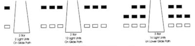
- Consists of either 2, 4, 6, 12, or 16 light units arranged in bars referred to as near, middle, and far bars.
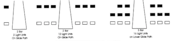
- Most VASI installations consist of 2 bars, near and far, and may consist of 2, 4, or 12 light units.
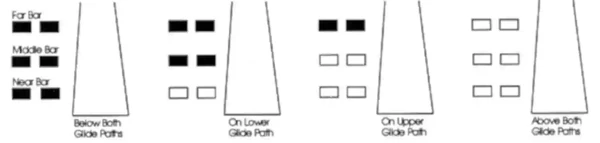
- Some VASIs consist of three bars, near, middle, and far, which provide an additional visual glide path to accommodate high cockpit aircraft.
- This installation may consist of either 6 or 16 light units.
- VASI installations consisting of 2, 4, or 6 light units are located on one side of the runway, usually the left.
- Where the installation consists of 12 or 16 light units, the units are located on both sides of the runway.
- Visible 3-5 miles during the day and up to 20 or more at night
-
VASI Lateral Guidance:
- Lateral course guidance is generally provided by the runway or runway lights.
-
VASI Vertical Guidance:
- The VASI consists of light units arranged in bars.
- There are two-bar and three-bar VASIs:
- A two-bar VASI consists of near and far bars that provide one visual glidepath, normally 3°.
- A three-bar VASI consists of near, middle, and far bars that provide two visual glidepaths.
- The lower path, provided by the near and middle bars, is normally 3°.
- The upper path, provided by the middle and far bars, is normally 1/4° higher and is intended only for high-cockpit aircraft to provide sufficient threshold-crossing height.
- If all lights of an operating three-bar VASI appear red as an airplane reaches MDA (Minimum Descent Altitude) during an instrument approach, the airplane is below the visual approach path. Level off at MDA until intercepting the appropriate visual path. Descend below MDA only when the required visual references are available and a normal descent to landing can be made; otherwise, execute the missed approach.
- Although normal glide path angles are 3°, angles at some locations may be as high as 4.5° for obstacle clearance.
- Pilots of high performance aircraft are cautioned that use of VASI angles in excess of 3.5° may cause an increase in runway length required for landing and rollout.
- VASIs normally provide safe obstruction clearance within plus or minus 10° of the extended runway centerline and to 4 nautical miles (NM) from the threshold.
- The published protection applies only within the defined lateral and distance limits.
- Descent using the VASI should not begin until the aircraft is visually aligned with the runway.
- In certain circumstances, the safe obstruction clearance area may be reduced by narrowing the beam width or shortening the usable distance due to local limitations, or the VASI may be offset from the extended runway centerline.
- This will be noted in the Chart Supplement U.S. and/or applicable Notices to Airmen (NOTAMs).
Rules of thumb:
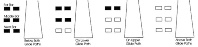
- For a conventional two-bar VASI, a white near bar and red far bar indicate on glidepath; both bars white indicate above glidepath, and both bars red indicate below glidepath.
- Red over red, you're dead.
- Red over white, you're alright.
- White over white, fly all night.
- To differentiate between a VASI and PAPI, think V, vertical.
Precision Approach Path Indicator
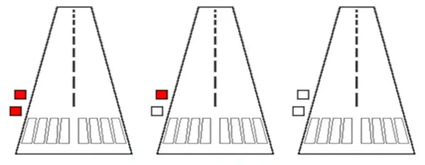
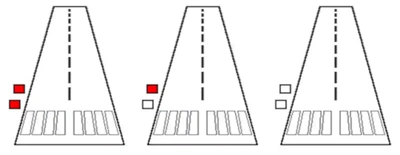
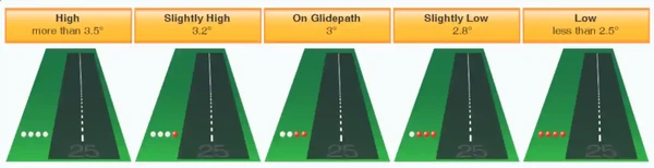
- Similar to a VASI, the Precision Approach Path Indicator, or PAPI, is installed in a single row of two or four light units. []
- On a four-light PAPI, two white and two red indicate on glidepath. More white lights indicate above glidepath, and more red lights indicate below glidepath; four white indicate well above and four red indicate well below.
- PAPI lights are visible from about 5 miles during the day and up to 20 miles at night.
- Usually installed on the left side of the runway
-
PAPI Lateral Guidance:
- Lateral course guidance provided by the runway or runway lights.
-
PAPI Vertical Guidance:
- Typically provides safe obstruction clearance within plus or minus 10° of the extended runway centerline and to 3.4 NM from the threshold.
- Descent using the PAPI should not begin until the aircraft is visually aligned with the runway.
- In certain circumstances, the safe obstruction clearance area may be reduced by narrowing the beam width or shortening the usable distance due to local limitations, or the PAPI may be offset from the extended runway centerline.
- This will be noted in the Chart Supplement U.S. and/or applicable NOTAMs.
Tri-Color System
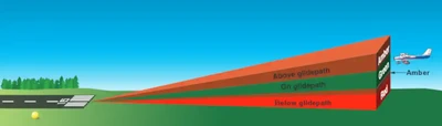
- A tri-color visual approach slope indicator uses a single light unit to project a three-color visual approach path into the runway's final approach area. []
- The system has a useful range of approximately ½ to 1 mile during the day and up to 5 miles at night, depending on visibility.
- The indications are red when below the glidepath, green when on the glidepath, and amber when above the glidepath.
- Because the system uses one light source, carefully locate and identify its signal to avoid confusing it with other lights.
- A dark amber color may appear briefly while descending through the transition from green to red.
- Do not mistake this transitional color for the amber above-glidepath indication.

Pulsating Systems
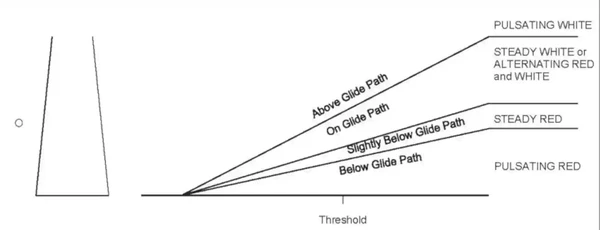
- Pulsating visual approach slope indicators normally consist of a single light unit projecting a two-color visual approach path. []
- The useful range is about 4 miles during the day and up to 10 miles at night.
- The on glide path indication may be a steady white light or alternating red and white light.
- The slightly below glide path indication is a steady red light.
- If the aircraft descends further below the glide path, the red light starts to pulsate.
- The above glide path indication is a pulsating white light.
- The pulsating rate increases as the aircraft gets further above or below the desired glide slope.
- As with the tri-color system, caution must be exercised not to confuse this system with other adjacent lights.
Alignment of Elements Systems
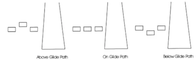
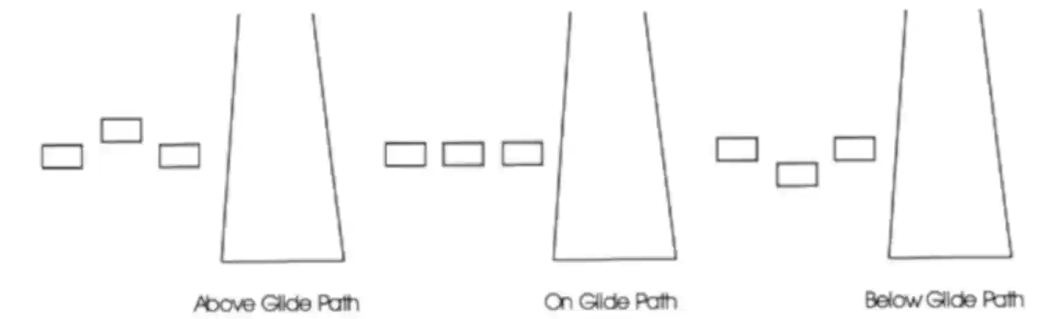
- Alignment of elements systems are installed on some small general aviation airports
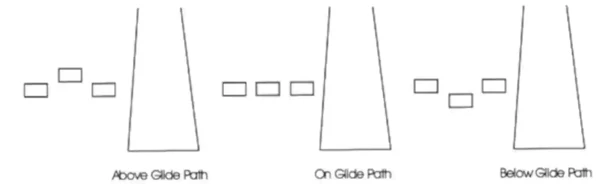
- Low cost painted plywood panels, normally black and white or fluorescent orange. []
- Some are lighted for night use
- Useful range is approximately 3/4 of a mile
- To use the system, the pilot positions the aircraft so the painted panels appear aligned.
Visual Glide Slope Indicator Regulation
- In Class D airspace, each pilot operating an airplane approaching to land on a runway served by a visual approach slope indicator must maintain an altitude at or above the glide path until a lower altitude is necessary for a safe landing.
Visual Glide-Slope Indicators Simulator
Hover over or tap an outlined feature to explore it. Select a topic from the list for an easier target on a small screen.
FAA Pacific source, PDF page 165. Edition: 3 September–29 October 2026. This is an instructional snapshot, not current operational information.
Try the light indications
Read all 6 explanations
PAPI
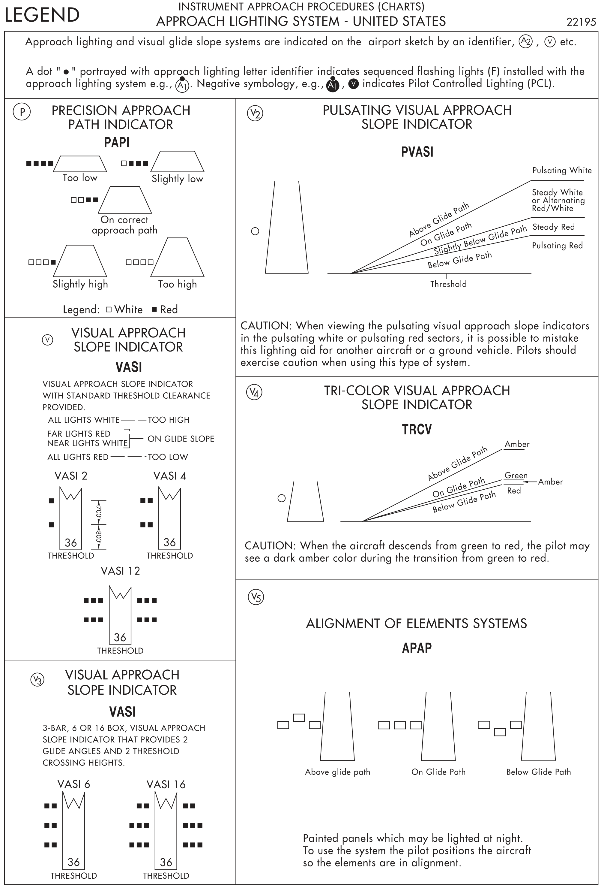
The Precision Approach Path Indicator (PAPI) uses four lights. Four red means too low; one white and three red means slightly low; two white and two red means on the correct approach path; three white and one red means slightly high; four white means too high.
Two-bar VASI
For the Visual Approach Slope Indicator (VASI) with standard obstacle clearance provided, all lights white means too high; far lights red and near lights white means on glide slope; all lights red means too low. The legend illustrates two-, four-, and twelve-box installations.
Three-bar VASI
A three-bar Visual Approach Slope Indicator (VASI), with six or sixteen boxes, provides two glide angles and two threshold-crossing heights. The near and middle bars provide the lower path; the middle and far bars provide the upper path, intended only for high-cockpit aircraft.
Pulsating VASI
The Pulsating Visual Approach Slope Indicator (PVASI) shows pulsating white above glide path, steady white or alternating red/white on glide path, steady red slightly below glide path, and pulsating red below glide path. The FAA cautions that pulsating white or red sectors may be mistaken for another aircraft or a ground vehicle.
Tri-color VASI
The Tri-Color Visual Approach Slope Indicator (TRCV) shows amber above glide path, green on glide path, and red below glide path. When descending from green to red, the pilot may see a dark amber color during the transition.
Alignment of elements
The APAP alignment-of-elements system uses painted panels that may be lighted at night. The pilot positions the aircraft so the elements are in alignment. The source illustrates above-, on-, and below-glide-path appearances.
Visual Glide Slope Indicators Interactive Scenario
The Arrival That Required Visual Glide Slope Indicators Judgment
Follow one developing flight from briefing through debrief. Each decision applies Visual Glide Slope Indicators knowledge to changing conditions, workload, and operational risk. Abbreviations used in this scenario: Aeronautical Information Manual (AIM).
Scenario Complete
Visual Glide Slope Indicators Knowledge Check
Choose the knowledge check that matches your current training for Visual Glide Slope Indicators.
 Private Pilot
PPL knowledge check
Core Knowledge Review
Review foundational knowledge, key concepts, and practical considerations. Topic: Visual Glide Slope Indicators.
- Immediate feedback
- Answer explanations
- Account progress tracking
Sport Pilot
Sport knowledge check
Sport Pilot Knowledge
Review the foundational knowledge and decisions used in sport-pilot operations. Topic: Visual Glide Slope Indicators.
- Immediate feedback
- Answer explanations
- Account progress tracking
 Commercial Pilot
CPL knowledge check
Advanced Application
Apply knowledge to advanced operations, risk management, and aeronautical decision-making. Topic: Visual Glide Slope Indicators.
- Immediate feedback
- Answer explanations
- Account progress tracking
 Instrument Rating (Airplane)
Instrument knowledge check
Instrument Knowledge
Practice the procedures, systems, weather, and decisions used in instrument flight. Topic: Visual Glide Slope Indicators.
- Immediate feedback
- Answer explanations
- Account progress tracking
 Flight Instructor
CFI knowledge check
Instructor Knowledge
Review the technical knowledge expected of an airplane flight instructor. Topic: Visual Glide Slope Indicators.
- Immediate feedback
- Answer explanations
- Account progress tracking
 Instrument Instructor
CFII knowledge check
Instrument Instructor Knowledge
Review instrument knowledge at the depth expected of an instrument flight instructor. Topic: Visual Glide Slope Indicators.
- Immediate feedback
- Answer explanations
- Account progress tracking
Why Take a Quiz?
Quizzes reinforce key concepts, identify knowledge gaps, and build confidence for real-world decisions. Quiz material is representative of the information provided here and is not based on or sourced from the Federal Aviation Administration test bank.
Visual Glide Slope Indicators Conclusion
- Two-bar VASI installations normally provide a 3-degree glidepath; local conditions may require a steeper angle.
- Check the Chart Supplement and applicable Notices to Airmen for published VASI or PAPI offsets and reduced obstruction-clearance areas.
- VASI and PAPI systems provide visual vertical guidance; lateral course guidance comes from the runway or runway lights.
- Under Title 14 of the Code of Federal Regulations (CFR) 91.129(e)(3), an airplane approaching a runway served by a visual approach slope indicator in Class D airspace must remain at or above the glidepath until a lower altitude is necessary for a safe landing. Sections 91.130 and 91.131 also incorporate the applicable 91.129 requirements in Class C and Class B airspace. Remaining at or slightly above the visual glidepath is recommended elsewhere unless another requirement or ATC (Air Traffic Control) authorization applies.
- Still looking for something? Continue searching:
Visual Glide Slope Indicators References
- Federal Aviation Administration (FAA) - Pilot/Controller Glossary.
- Aeronautical Information Manual (2-1-2) Visual Glideslope Indicators.
- CFI Notebook.net - Chart Supplement U.S..
- CFI Notebook.net - Notices to Airmen.
- Flight Information Handbook (FIH)
- Instrument Flying Handbook.
- FAA JO (6850.2B) Visual Guidance Lighting Systems.
- Pilot Handbook of Aeronautical Knowledge
- Airplane Flying Handbook